
Front Page
Desiccant Air Dryers
AHLD E-Series
Heatless Regenerative
Models 70, 100, 150, 200, 250, 300, 350,
450, 500, 600, 750, 1000, 1250, 1500,
2000, 2500, 3000, 3500, 4500, 5000 scfm
Installation
& Operations
Manual
Eective October 2017

AHLD Series | Heatless Regenerative Desiccant Air Dryer
2
DRYER DATA SHEET
INTRODUCTION
Model Number: Serial Number:
Dryer Type: Date of Manufacture:
Ship Date: Installation Date:
Customer Name:
Customer Address:
Customer City: State/Zip:
Accessories:
Other:
Thank you for purchasing Aircel’s AHLD E-Series Heatless Regenerative Desiccant Air Dryer with integrated Energy Management
Purge Reduction System. You are now the proud owner of one of the nest desiccant dryers on the market. Aircel AHLD E-Series
dryers are engineered and manufactured to provide you with many years of trouble-free service and provides energy ecient
operation by reducing the overall dry purge air required for regeneration, saving energy and money. To ensure that you get rst
class service from this equipment, we recommend you take some time and read the contents of this manual.
This manual contains all the information required for installing and maintaining your new equipment. It also includes the safety
procedures and corresponding drawings. We strongly suggest that all personnel involved with the machine, read the entire
contents of the manual before proceeding with the installation or maintenance activities.
The manufacturer reserves the right to make changes without any prior notication and is not obligated in any manner.
Infomration in this manual is deemed current at the time of publication and Aircel disclaims all liability for any errors resulting in
any loss or damage.
If you have questions, need additional copies, or would like to schedule an Aircel service technician viist, contact your distributor.

Heatless Regenerative Desiccant Air Dryer | AHLD Series
3
DRYER DATA SHEET
Dryer Inlet Air Flow Rate:
Dryer Inlet Temperature:
Dryer Ambient Temperature:
Dryer Voltage:
Dryer MCA Minimum Circuit Ampacity:
Dryer MOP Maximum Overcurrent Protection:
Dryer Operating Pressure:
Dryer Maximum Operating Pressure:
Dryer Vessel Pressure Relief Valve Setting:
Dryer Desiccant Type:
Dryer Desiccant Weight Total for System:
Dryer Outlet Dew Point:
Dryer Control Time Cycle:
Dryer EMS Dew Point Sensor Setting (for sensor outlet dew point):
High Dew Point Setting:
Demand Cycle Setting:
Outlet Dew Point Readout on Display:
Electrical Drawing Number:
Mechanical Drawing Number:
PLC Software Program Number:
Control Air Filter Element Number:
Inlet Pre-Filter Element Number (option):
Outlet After-Filter Element Number (option):
Inlet Valve:
Purge Exhaust Valve:
Vessel National Board Number (Left and Right Vessels):
Dryer System Weight:

AHLD Series | Heatless Regenerative Desiccant Air Dryer
4
TABLE OF CONTENTS
Dryer Data Sheet 2
Introduction 2
Dryer Data Sheet 3
Safety Precautions 5
Safety Symbols 6
General Safety Instructions 7
Desiccant Safety Precautions 8
Why We Need Compressed Air Dryers 9
Purpose and Intended Use 9
Inspection on Arrival 9
Features & Options 10
Design Parameters 11
Dryer Description 11
How It Works 11
Flow Diagram 12
Installation 13
Pre-requisites for Installation 13
Location 13
Typical Installation Diagram 13
Installation Steps 14
Start-Up and Shut Down Procedures 15
Sequence of Operation 16
Maintenance 17
Weekly Checklist 17
Semi-Annual Checklist 17
Annual Checklist 17
Normal Operation Setup 18
Aircel Programmable Controller (APC) 19
System Navigation 19
Dryer Operations 20
Main Screen Navigation 24
Control Menu Navigation 24
Control Menu Operation 25
Settings Screen Operation 25
Time Control Main Navigation 26
Time Control Menu Operation 26
Analog Screen Navigation 27
Hours of Operation Screen Navigation 27
Alarm Screen Navigation 28
Alarm Pop-Up Screens 29
Troubleshooting Table 30
Appendix 32
Desiccant Material Data Safety Sheet 32
Drawings 37
Service Notes 43
Warranty 47

Heatless Regenerative Desiccant Air Dryer | AHLD Series
5
Notice: For optimum performance, use only Aircel replacement parts.
Notice: For information and notes specific to custom designed and built dryers, reference the drawing package
provided with the unit. See warranty on manual back cover for custom engineered products.
NOTICE
Throughout this manual, signal words are present to advise of safety
precautions and/or standard practices. Obey these signal words as dened
below:
DANGER! - Indicates an imminently hazardous situation which, if not
avoided, will result in death or serious injury.
WARNING! - Indicates a potentially hazardous situation which, if not
avoided, could result in death or serious injury.
CAUTION! - Indicates a potentially hazardous situation which, if not
avoided, may result in minor or moderate injury.
Notice: used to address practices not related to personal injury.
WARNING!
GENERAL SAFETY PROCEDURES:
• Improper installation, operation, or maintenance may contribute to conditions in the work area or facility that could
result in personal injury and product or property damage. Check that all equipment is properly selected and sized for
the intended use.
• Consult and comply with national and local codes relating to fire or explosion and all other appropriate codes when
determining the location and operation of this equipment.
• Safe and efficient operation of the unit depends on proper installation.
• Authorities with jurisdiction should be consulted before installing to verify local codes and installation procedures. In
the absence of such codes, install unit according to the National Electric Code, NFPA No. 70-latest edition.
• A qualified installation and service agent must complete installation and service of this equipment.
• DO NOT weld on / to pressure vessel or modify it in any way.
• DO NOT remove, modify, or adjust protective or safety devices.
• Lock out power supply and depressurize system before performing maintenance or service work.
• DO NOT operate the equipment with the control panel door open.

AHLD Series | Heatless Regenerative Desiccant Air Dryer
6
SAFETY INSTRUCTIONS
Safety Symbols Used in Manual
IMPORTANT INFORMATION: Readers of the manual must pay extra attention to instructions and information
succeeding this symbol.
WARNING: This indicates that it is dangerous and could result in physical injury and death if the instructions are
not followed correctly.
ELECTRICAL DANGER HIGH VOLTAGE: This means that there is a risk of electrical shock and only authorized
personnel with proper gear must approach it.
HIGH NOISE AREA: All personnel are required to wear ear protectors before approaching the vicinity of the
equipment.
HAZARDOUS FUMES & GASES: Personnel must wear protective gear to prevent inhaling of the gases and fumes.
SUSPENSION POINTS: Look for these symbols before making any attempt to move or relocate your equipment
.
TIPS & SUGGESTIONS: Following these tips can make your work easier.
EXTREME CAUTION: This indicates that there might be possible risk of material damage and personnel are
advised to exercise extra caution.
!
X

Heatless Regenerative Desiccant Air Dryer | AHLD Series
7
GENERAL SAFETY INSTRUCTIONS
What You Must Do
1. Certified/authorized electricians must perform electrical work.
2. Electrical work must conform to the specifications indicated by Aircel and any local or state laws that may apply.
3. Personnel must wear appropriate safety gear before working on any electrical or mechanical aspects of the
machine.
4. Appropriate tools have to be used for all installation and maintenance work. If special tools are required and are
not available to the installation crew, contact the factory or your Aircel representative.
5. A copy of the Operation Manual must be made available to all personnel involved with the installation, operation,
and maintenance of the equipment.
6. Before performing any maintenance operations on the equipment, the unit must be shut down, isolated, electrical
power removed, and completely depressurized.
7. To ensure compatibility and continued trouble free operation, only genuine Aircel parts must be used.
Safe Operating Procedures
1. Pressurize and depressurize compressed air SLOWLY! Always open air valves slowly when pressurizing the airline
system or equipment. Repair air slowly when depressurizing your air system or equipment.
2. Circuit breakers, fusable disconnect, and wiring should conform to national and/or local electrical codes. Make
certain that qualified electrical personnel perform the electrical installation for this unit.
3. Only use original fuses for the rated voltage and current.
4. Shut down the unit in the correct recommended procedure.
5. Before any work on system, always depressurize the unit and remove all electrical power.
6. After shut down, put up warning notice to prevent the unit from being switched “ON” accidentally.
7. Inspect all piping, hoses, and connections. Make sure that all hoses are in good condition and are rated for the
correct working pressure. Do not allow hoses to come into contact with oils, chemicals, or sharp objects.
8. Secure condensate drain lines. Unsecured, flexible drain lines may whip violently under pressure and may cause
bodily harm.
Aircel air dryers do not remove carbon monoxide (CO) and are not safe for human respiration (breathing). Breathing air
must be at least Grade D quality as described in Compressed Air and Gas Association (CAGI) commodity specifications
67.1-1966. User may refer to OSHA 29 CFI 1910.134 for special precautions and equipment suitable for breathing air
applications. Aircel disclaims any liability whatsoever for loss, injury, or damage.
What You Must Not Do
1. Do not make any constructional changes to the unit. Only Aircel or its authorized representatives with the prior
approval can perform any constructional work on the machine.
2. Do not use foreign parts.
3. Compressed air from the dryers is not to be used for breathing purposes - install a breathing air package to
ensure conformance with OSHA regulations.
4. Do not disable or disengage any protective equipment used on the machine.
X
!
!

AHLD Series | Heatless Regenerative Desiccant Air Dryer
8
DESICCANT SAFETY PRECAUTIONS
Desiccant First Aid
Recommendations
INHALATION
Use a contoured dust mask during loading and
unloading operations. If high concentrations are inhaled,
immediately move to fresh air. Keep person calm. If
not breathing, give articial respiration. If breathing is
dicult, give oxygen. Call a physician.
SKIN CONTACT
In case of contact, immediately flush skin with plenty of
soap and water for at least 15 minutes.
EYE CONTACT
In case of contact, immediately flush eyes with plenty of
water for at least 15 minutes. Call a physician.
SPILLS
Clean accidental spills by vacuuming, sweeping, or
flushing to a sewer treated for suspended solids. Avoid
creating excess dust.
WARNING!
INHALATION, SKIN, & EYE IRRITANT:
The desiccant used in this equipment is not considered
hazardous. Contact with and disposal of desiccant
must be in accordance with the relevant MSDS and
all local codes and regulations. The following lists the
more common safety measures to be observed during
loading and unloading operations. Reference the MSDS
in the appendix for complete safety measures.
!

Heatless Regenerative Desiccant Air Dryer | AHLD Series
9
WARNING!
• Failure to lift the unit correctly can result
in sever personal injury or property
damage.
• Use appropriate lifting equipment and
adopt all safety precautions needed for
moving and handling the equipment.
• A hand cart, fork lift, or crane is
recommended for unloading and
installation.
• Lift unit by lifting lugs and frame only. Do
not lift by piping.
!
WARNING!
• Follow proper lock out/tag out
procedures before performing service or
maintenance work.
• Electrical installation must be performed
by a qualied electrician and comply with
all applicable national and local codes.
!
CAUTION!
• A copy of the Operation Manual must be
made available to all personnel involved
with the installation, operation, and
maintenance of the equipment, to avoid
injury to personnel or property damage.
• Appropriate tools must be used for all
installation and maintenance work, to
avoid injury to personnel or property
damage.
!
Why We Need Compressed Air Dryers
Untreated compressed air contains many contaminants such
as water, compressor oil, pipe scale, and contamination from
ambient air. All these contaminants cause excessive corrosion,
erosion, freezing, and regenerative type dryer system with all
recommended ltration will remove these contaminants to
harmless levels. The end result is that instruments that come
in contact with the dry compressed air stay clean and do not
corrode, therefore lasting much longer. Products that may
come in contact with clean, dry, compressed air are virtually
unaected. Therefore, rejection rates are reduced.
Purpose and Intended Use
Misuse or modication of this equipment may result in personal
injury. Do not misuse or modify. The high eciency heated
regenerative desiccant dryer is used exclusively for purifying
compressed air in non-hazardous locations.
The state-of-the-art system is designed and constructed
in accordance with the rules and regulations regarding
adsorption technology and industrial safety. There are hazards
accompanying this type of product if not operated for the
intended purpose by trained and specialized personnel.
Inspection on Arrival
All heated regenerative desiccant dryers are tested and
operated before shipment. However, shipping vibration may
cause damage such as loosening of certain parts. To ensure
smooth installation, it is recommended that immediately upon
receipt of the unit, the system is checked for the following:
1. Inspect unity on delivery.
2. Report any damage to the delivery carrier.
3. Request a written inspection report from the Claims
Inspector to substantiate the claim.
4. File claims with the delivery carrier.
5. Compare unit received with description of product ordered.
Check the serial plate label and make sure that it is the
correct Model was ordered. Note the equipment Capacity
and Power Supply requirements and ensure that they are
in accordance with your specifications. The rated conditions
of the dryer are indicated on the serial plate label. If there
is any discrepancy, contact your representative listed on
the manual back cover.
6. Vibration during shipping can loosen the connections.
Inspect all pipe and tubing and make sure they are all
tightened and secured.
7. Report incomplete shipments to the delivery carrier and
your service representative.

AHLD Series | Heatless Regenerative Desiccant Air Dryer
10
FEATURES & OPTIONS
Standard Features
• Integrated Energy Management Purge Reduction System for ecient energy savings and reduced cost of operation.
• Optimal tower size for low velocities reducing desiccant uidization, and high contact time for ecient low dew point
performance.
• Tower pressure relief valves.
• Standard design capacity based on 100 psig, 100°F inlet air, 100°F ambient air, and Pressure dew point of -40°F.
• Purge exhaust muers for quiet operation.
• Tower pressure gauges for additional visual operation of dryer operation.
• Stainless steel desiccant supports and air diusers to prevent channeling.
• Counter-current reactivation for ecient desiccant regeneration.
• PLC Controlled Electrical System
• Adjustable (5 min., 10 min.) cycle times: 10 minute cycle for the standard -40°F Pressure dew point outlett dew point
systems, 5 minute cycle used in the optional -100°F Pressure dew point outlet dew point systems.
• Controlled repressurization to slowly repressurize the regenerated vessel to line pressure prior to switch over preventing
desiccant bed movement and attrition.
• Fail safe design: Failure of power and/or pilot air causes the purge exhaust valves to close, eliminating loss of air pressure.
The system also provides uninterrupted drying air ow, preventing a deadheading aect.
• Control pilot air lter provides clean air to air control system for long trouble-free reliable operation.
• Desiccant towers are designed, fabricated, and stamped according to ASME code.
• Desiccant ll and drain ports for ease of desiccant replacement.
• Structural steel frame.
• Highly reliable non-lubricated air inlet and outlet valves (APV) Automatic Piston Valve (AHLD 70 E - AHLD 750 E) and high
performance, non-lubricated buttery valves (AHLD-1000 E - AHLD-1500 E).
• Highly reliable angle seat design purge exhaust valves.
• Tower operating LED status lights (left and right tower dryer, left and right tower regenerating).
• On/O switch and power On light.
• NEMA 4 weather resistant electrical system construction.
Additional Options
• -100°F outlet pressure dew point.
• Failure-to-shift alarm with pressure transducers.
• Outlet dew point sensor with dew point readout on system display.
• High humidity alarm.
• Outlet dew point 4-20 ma signal.
• Mounted, piped, and wired ltration packages.

Heatless Regenerative Desiccant Air Dryer | AHLD Series
11
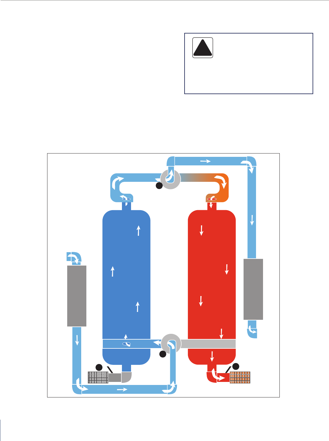
How It Works
1. Moisture saturated compressed air enters the coalescing
pre-lter, where aerosols are coalesced then drained via
an automatic drain system.
2. The moist water vapor-laden inlet air free of liquid
water ows to the inlet of the dryer through the APV
(Automatic Piston Valve) (A), which diverts the inlet air to
one of the towers - in this example, Tower 1.
3. Air ows upward through the adsorbent bed removing
the moisture vapor; the dried airow exits the tower
through the outlet valve (B), owing to the outlet
particulate after lter, which removes particulates
from the air stream. Clean and dry air now ows to the
customer process air distribution system.
4. As one tower is drying air, the other tower will be
regenerating (purging) the adsorbent bed. In this
example, Tower 2 will be regenerating. Prior to
regeneration, the exhaust valve (C) is opened and the
tower is depressurized to near atmospheric pressure, the
tower will now be regenerating. During the regenerating
process, a small portion of dry outlet compressed air is
used, 15% on average based on standard design capacity
of 100 psig, 100°F inlet air, 100°F ambient air, and
pressure dew point of -40°F.
5. The dry regeneration airow is channeled through
the outlet orice to the regenerating tower, removing
moisture from the adsorbent bed and exits the
regenerating tower through exhaust valve (C) and
exhaust muer to ambient. After regeneration cycle
is complete, valve (C) closes, causing Tower 2 to
repressurize to line pressure.
6. Next, the tower will switch when exhaust valve (D)
opens, causing Tower 1 to depressurize and regenerate.
Simultaneously, the inlet and outlet APV valves (A) will
shift the pistons to the low pressure Tower 1, causing
the inlet airow to be diverted to Tower 2, which will now
be the drying tower. This switching process will continue
repeatedly.
7. The dryer control system is completely automatic and
cycles the system through the drying and regeneration
cycles. The standard cycle drying time is 5 minutes,
regeneration cycle is 4 minutes, and repressurizing cycle
is 1 minute.
DESIGN PARAMETERS
DRYER DESCRIPTION
Type of dryer: Desiccant
Power supply: 460 Volt / Three Phase / 60Hz
Desiccant type: Premium Grade Activated Alumina
All Models
Parameter
Description Air Pressure
Air Inlet
Temperature
Ambient
Temperature
Maximum 135 psig 120 (°F) 120 (°F)
Minimum 60 psig 40 (°F) 38 (°F)
AHLD Series | Heatless Regenerative Desiccant Air Dryer
12
A
D
B
C
D
Pre-Filter
Tower 1 Tower 2
After Filter
TYPICAL SCHEMATIC FLOW DIAGRAM
8. The Aircel AHLD E-Series Heatless Dryer incorporates a
unique energy saving control system to reduce purge
air loss with its integrated Energy Management Purge
Reduction System. This system utilizes a moisture
sensor sampling the air from mid-bed of the on-stream
drying tower, after the xed purge time is complete,
the regenerating/purging tower will repressurize. If the
moisture sensor senses a low moisture condition or low
load in the drying tower, the drying tower will remain
in the drying mode after the xed drying time cycle for
an extended period of time. The end result is an overall
purge reduction and signicant energy savings.
CAUTION!
• Do not misuse or modify under any
conditions. Misuse or modication of this
equipment may result in personal injury.
!

Heatless Regenerative Desiccant Air Dryer | AHLD Series
13
INSTALLATION
Pre-requisites for Installation
To ensure a safe and smooth installation, we recommend you
go through the steps indicated below:
• Make sure that all personnel involved have read this
operation manual thoroughly. If you have any questions,
please contact your Aircel represenative or the factory
and we will be glad to assist you. If you need help with
the commissioning, we will be glad to schedule an
Aircel factory service technician to visit your site and
commission the dryer for a nominal fee.
• Have extra copies of the operation manual.
• Special care must be taken while transporting the unit to
the installation site.
• Dryer must not be moved or lifted by the attached piping.
Location
• Careful consideration should be given to the location of
the dryer in order to assure optimum results. Ensure that
the load bearing weight of the floor is adequate for the
weight of the dryer.
• The dryer should be located in an open area and a level
ground. Dryer should be bolted to the floor to eliminate
vibrations.
• The ambient temperature should be between 40°F and
100°F. Low temperature could affect the dryer process
and result in high outlet dew point.
• In conditions where the ambient drops below freezing,
Aircel recommends the use of heat trace on any
coalescing filter sumps and drain lines and the use of
heated type draings.
• Dryer and accompanying filters should be installed with
at least 2-5 feet clearance from the adjoining walls to
provide easy access for routine maintenance.
Drain
Valve
Air or Water
Cooled
Condenser
Air
Compressor
Drain
Valve
Dry Air
to Plant
Drain
Valve
Drain
Valve
After Filter
Pre-Filter
Separator
TYPICAL INSTALLATION DIAGRAM

AHLD Series | Heatless Regenerative Desiccant Air Dryer
14
INSTALLATION
Only qualied personnel should make electrical and
mechanical connections.
• EQUIPMENT FOR INSTALLATION: This dryer does not
need any special tools for installationFoundation: Dryer
should be mounted on a suitably structured flat and level
floor or base that is free from vibration. Special care must
be used when lifting the dryer to prevent tip-over.
• MOUNTING: Bolt dryer to the foundation using the bolt
holes provided in the frame.
• PIPING: Connect the inlet of the dryer to the moist gas
from the compressor/receiver/inlet filter. Install the
inlet piping and the inlet shutoff valve, Install the Outlet
piping and the outlet shutoff valve (a union with a valve
by-pass can be installed at the inlet and outlet valves to
accommodate isolation of the dryer for maintenance).
Compressed air piping has to be least the same size as
the of the inlet and outlet connections of the dryers.
Larger pipe sizes can be used with reducers.
• BACK PRESSURE REGULATOR: Install backpressure
regulator to prevent any possibility of fluidization of
the desiccant bed. When there is a sudden increase
in the demand for compressed air downstream of the
dryer, a huge pressure drop develops and can affect
the performance of the dryer and the drying material
(desiccant).
• DESICCANT: Make sure that the dryer towers are filled
with desiccant. Larger dryers may have desiccant shipped
separately – in which case, the media has to be filled into
the pressure vessels from the desiccant fill ports. Care
must be taken when filling the media and it must be done
gradually to prevent powdering.
• MUFFLER: If the event that mufflers have been shipped
loose, they must be installed and secured.
• BY-PASS: If the dryer is not supplied with optional by-pass
valve it is highly recommended that by-pass valve be
installed around the dryer and filters. These by-pass shut-
off valves will permit the dryer and filters to be removed
from the compressed air system for servicing without
shutting down the entire compress air system.
• ELECTRICAL: Make all electrical connections to the dryer
as shown on the wiring diagram. Special care must be
taken in connecting the proper voltage as indicated on the
specification sheet and wiring schematic.
• ADDITIONAL VALVING/PIPING: When installing
equipment or components keep in mind the serviceability
of the equipment and provide additional valves to isolate,
bypass, and to depressurize as needed.
• EXHAUST: If you intend to vent your exhaust with
additional piping, the discharge piping from the exhaust
should not be piped upward without arrangement for
removing trapped condensate. Make sure that you do not
apply a backpressure on this exhaust system. If exhaust
piping is to be extended, try to stay within 15 to 20 feet
and use the next larger pipe size.
NOTE: It is mandatory that dryer be grounded. Use of
your plants frame as a ground may cause problems with
the control. A fused disconnect is not supplied with this
equipment therefore one must be supplied by customer. All
electrical fuses, breakers, etc. should be properly sized.
Aircel is not liable for any code violations, component damage,
downtime, or consequential damage related to customer
supplied electrical components and connections.

Heatless Regenerative Desiccant Air Dryer | AHLD Series
15
START-UP AND SHUT DOWN PROCEDURES
Start-Up Procedure
At any point during the process of startup or shutdown,
you notice anything unusual; we recommend you refer to
the operation manual immediately. If you cannot nd the
answer in the troubleshooting section, contact your Aircel
representative or the factory at once.
1. Ensure that the dryer is connected to a suitable
compressed air supply. Make sure that the pressure of
the supply is equal to the normal operating pressure of
the dryer.
2. Check to make sure the “shut-off” valves are closed and
that by-pass valve is open.
3. Close all manual drain/vent valves.
4. Slowly pressurize the dryer by gradually (slowly) opening
the inlet shut-off valve to the OPEN position.
5. When both towers of the dryer are completely
pressurized, check the complete system for possible air
leaks. Use soap and water to test all joints and fittings. If
any leaks are detected, immediately depressurize the unit
and correct the leaks.
6. Make certain that nay automatic condensate drain
isolation valves are in the open position so proper
condensate draining can occur.
7. When normal operating pressure is reached, switch on
electrical power (Turn switch to ON position).
8. With by-pass valve closed, open the outlet valve slowly to
allow air downstream.
9. When energized one of the towers should depressurize.
10. Check the operation of several cycles completely by
following the control panel display screen operation, the
panel lights on the electrical box, and the tower pressure
gauges to make certain the dryer system is operating as
displayed. Also refer to the how it works section, flow
diagram, electrical drawing, dryer control display screen
descriptions, and sequence of operation in this manual
for reference.
11. Check the drain valve for proper operation and discharge
of liquid (filters and separators, etc.).
12. Near the dryer outlet (APV) valve, check the control air/
pilot air regulator secondary pressure, the regulator
gauge should read 100 psig. Increase or decrease
regulator knob to achieve a 100 psig control air secondary
pressure reading.
13. Make certain the purge exhaust valves slowly open
within an 8 to 12 second time period, some adjustment
of the flow control valve attached to the actuator may be
required, after adjustment tighten down the locking collar.
14. Make certain a slight amount of air flow is felt at the end
of the EMS RH sensor sample cell exhaust coil tube (this
is normally located at the back of the dryer) adjust the
needle valve to give more or less flow.
15. Review the dryer system display screen shots (in this
manual) to make certain the parameters are set as
needed in the customer dryer.
16. Purge air flow is preset and not adjustable.
After the initial startup, the dryer operation is completely
automatic. To understand the details of the operation, we
recommend you use the how it works section, flow diagram,
electrical drawing, dryer control display screen descriptions,
and sequence of operation in this manual for reference.
Shut-Down Procedure
At any point during the process of startup or shutdown,
you notice anything unusual; we recommend you refer to
the operation manual immediately. If you cannot nd the
answer in the troubleshooting section, contact your Aircel
representative or the factory at once.
1. Slowly OPEN the by-pass valve.
2. Slowly CLOSE the Inlet and outlet “shut-off” valves.
3. To depressurize the dryer after the Dryer is isolated. Turn
the power ON … a purge exhaust valve will open and
the dryer system starts to depressurize, also the manual
vent valve on the outlet afterfilter can be opened to
depressurize the Dryer until the tower pressure gauges
read ‘0’ psig.
4. Switch off electrical power after both towers have been
depressurized.

AHLD Series | Heatless Regenerative Desiccant Air Dryer
16
SEQUENCE OF OPERATION
1. STEP ONE - Vessel 2 Depressurizing (0 - 5 seconds):
Vessel 2 (T2) purge exhaust pilot solenoid valve is
energized which supplies control air to the purge
exhaust valve (V4) which opens slowly, depressurizing
vessel 2 (T2). Simultaneously the inlet valves V1 and V2
shift positions with a pneumatic signal from vessel 2
(T2) purge exhaust pilot solenoid valve to the inlet tower
selector pneumatic pilot valve which in-turn supplies a
pneumatic signal to the inlet valve (V1) and close valve
(V2), directing the inlet air to vessel 1 (T1) to be drying
the air. The air flows up through the desiccant bed and
exits to the outlet valve (V5) to the outlet particulate
filter then to custom dry process air system.
2. STEP TWO - Vessel 2 Regenerating (6 - 240 seconds):
Step 2 is a continuation of step 1 except vessel 2 (T2)
will be regenerating, vessel 2 (T2) purge exhaust valve
(V4 is still open vessel 1 (T1) is drying the inlet air. A
small portion of dry outlet air from vessel 1 (T1) (15%
average based on standard design capacity of 100 psig,
100°F inlet air, 100°F ambient air and PDP of -40°F is
taken through a small orifice in the outlet line and used
to regenerate the desiccant bed in vessel 2 (T2) until
240 seconds has been reached.
3. STEP THREE - Vessel 2 Repressurizing (241 - 300
seconds):
Vessel 2 (T2) purge exhaust pilot solenoid valve will
de-energize causing vessel 2 (T2) purge exhaust valve
(V4) to close, this allows vessel 2 (T2) to repressurize to
line pressure, since air continues flowing through the
small outlet orifice pressurizing vessel 2 (T2). The inlet
tower selector pneumatic pilot valve maintains the inlet
valve (V1 & V2) positions.
4. STEP FOUR - Vessel 1 Extended Drying:
A few seconds before the end of repressurization
the AHLD E-SERIES Controller’s integrated Energy
Management Purge Reduction System looks at the
moisture sensor, if the moisture load is low enough,
vessel 1 (T1) will continue to dry for an extended drying
period until the moisture load has reached a set high
level, the controller will then advance to step 5 and
the vessels will switch. This feature reduces the overall
purge consumption saving energy and money.
5. STEP FIVE - Vessel 1 Depressurizing (0 - 5 seconds):
Vessel 1 (T1) purge exhaust pilot solenoid valve is
energized which supplies control air to the purge
exhaust valve (V3) which opens slowly, depressurizing
vessel 1 (T1). Simultaneously the inlet valves V2 and
V1 shift positions with a pneumatic signal form vessel
1 (T1) purge exhaust pilot solenoid valve to the inlet
tower selector pneumatic pilot valve which in-turn
supplies a pneumatic signal to the inlet air to vessel
2 (T2) to be drying the air. The air flows up through
the desiccant bed and exits to the outlet valve (V6) to
the outlet particulate filter then to the customer dry
process air system.
6. STEP SIX - Vessel 1 Regenerating (6 - 240 seconds):
Step 6 is a continuation of step 5 except vessel 1 (T1)
will be regenerating, vessel 1 (T1) purge exhaust valve
(V3) is still open, vessel 2 (T2) is drying the inlet air.
A small portion of dry outlet air from vessel 2 (15%
average based on standard design capacity of 100 psig,
100°F ambient air and PDP of -40°F) is taken through a
small orifice in the outlet line and used to regenerate
the desiccant bed in vessel 1 (T1) until 240 seconds has
been reached.
7. STEP SEVEN - Vessel 1 Repressurizing (241 - 300
seconds):
Vessel 1 (T1) purge exhaust pilot solenoid valve will
de-energize causing vessel 1 (T1) purge exhaust valve
(V3) to close, this allows vessel 1 (T1) to repressurize to
line pressure, since air continues flowing through the
small outlet orifice pressurizing vessel 1 (T1). The inlet
tower selector pneumatic pilot valve maintains the inlet
valve (V2 and V1) positions.
8. STEP EIGHT - Vessel 2 Extended Drying:
A few seconds before the end of repressurization
the AHLD E-SERIES Controller’s integrated Energy
Management Purge Reduction System looks at the
moisture sensor, if the moisture load is low enough,
vessel 2 (T2) will continue to dry for an extended drying
period until the moisture load has reached a set high
level, the controller will then advance to step 1 and
the vessels will switch. This feature reduces the overall
purge consumption saving energy and money.

Heatless Regenerative Desiccant Air Dryer | AHLD Series
17
MAINTENANCE
Maintenance
Prior to performing and maintenance on the dryer, all
personnel are strongly advised to familiarize themselves
with the equipment by reading the entire contents of
this operation manual. Aircel strongly recommends the
strict adherence of all the safety procedures prior to any
performing and maintenance activity on the dryer.
1. The pressure differential indicator referred to as the
“Delta-P” is a very good indicator of the state of the filter
elements. Maintenance personnel must pay attention
to these to keep the drying running with full efficiency
Change filter elements on a regular basis, once a year
maximum for a 1-shift operation. Change more frequently
if operating 2 or 3 shifts such as every 6 months.
2. The useful life of a filter element depends on the quality
of air. Free open areas for input and exhaust will ensure
lesser intake of dirt and particles.
3. Powder desiccant can accumulate in the muffler and
increase the backpressure in the regenerating tower
change mufflers on a regular basis typically every 2-3
months for optimum performance.
4. Oil and oil vaper can drastically reduce the life of the
desiccant. Take precautions to eliminate all traces of oil
from the airflow.
5. Fluctuating dew point indicates uneven drying and
regeneration between the towers, an exhaust valve may
not be working properly or muffler may be clogged or
dirty, also vessel diffuser screen may be clogged.
Weekly Checklist
1. Check all drain valves, prefilter, afterfilter and separators.
2. Check any pressure differential indicators (Delta-P) on
the pre-filter and afterfilter (filter elements should still be
changed on regular basis once a year maximum for a 1
shift operation. Change more frequently if operating 2 or
3 shifts such as every 6 months).
3. Check dryer for correct operation.
4. Verify dryer is purging at the purge exhaust, after dryer
depressurizes.
5. Check the dew point (if available) to ensure the dew point
is being achieved.
6. Check back pressure in regenerating tower, if more than a
few psig on the pressure gauge, clean or replace exhaust
mufflers (change mufflers on a regular basis typically
every 2-3 months for optimum performance).
Semi-Annual Checklist
1. Remove and inspect all filters for excessive particulate
loading and physical damage – if required replace
prefilters, afterfilters, pilot air filter and mufflers (filter
elements should still be changed on regular basis once
a year maximum for a 1 shift operation. Change more
frequently if operating 2 or 3 shifts such as every 6
months).
2. Check pressure differential indicator and if it turns red,
replace the element.
3. Remove exhaust mufflers. Knock out excess particulate
and back flow with dry compressed air. If particulate
cannot be removed completely change the exhaust
mufflers. Check backpressure in regenerating tower,
if more than a few psig on the pressure gauge, clean
or replace exhaust mufflers. (Change mufflers on a
regular basis typically every 2-3 months for optimum
performance).
4. Check desiccant condition. Powder in the mufflers is an
indication of the status of the desiccant.
5. Check all solenoid valves – coil condition and control
circuit.
6. Check dryer operation.
7. Inspect and clean inlet and outlet APV (Automatic Piston
Valves).
Annual Checklist
1. Replace elements in prefilters, afterfilters, and pilot air
filter.
2. Replace mufflers.
3. Recalibrate dew point analyzer probe (if used) or send
back to factory for recalibration.
4. Check inlet and outlet valve seals. Clean or replace as
needed.
5. Check dryer for proper operation
WARNING!
• Follow any proper lock out/tag out procedure
before performing service or maintenance work.
• Follow all safety procedures prior to performing any
maintenance activiting on the dryer.
!

AHLD Series | Heatless Regenerative Desiccant Air Dryer
18
NORMAL OPERATION SETUP
Normal Dryer System Operation Setup
The following operational sequence should be followed for normal dryer system operation.
1. Make certain all gauge isolation valves, vent valves,
instrument valves, pre-filter drain valves, etc. are in the
correct positions.
2. Make certain the system has been pressurized to line
pressure.
3. Ensure blower intake adjustment valve has been preset
and locked down. Slight adjustment might be needed to
maintain 400°F downstream of heater during the heat
regeneration cycle.
4. Verify control air has pressure, set at 100 psi
5. Confirm the valve upstream of the dew point sensor is
fully open, and valve downstream of the dew point sensor
is slightly open - a slight air flow should be noticed at the
end of the exhaust coil.
6. The Power On/Off switch is set to ON.
7. The System On/Off button must be turned On. This is
accomplished by pressing the System On button on the
control panel in the Main Menu screen. The color will be
green for on and red for off.
8. Service Mode should not be active. Service Mode will not
be visible or shown on the Running Sequence screens
when not active. If Service Mode is shown, the service
routine is active and needs to be place into normal
operation. To deactivate Service Mode from the Running/
Step screens, press the Screen Unlock button until it starts
blinking, then press the Main Menu button, displaying
the Control/Main screen. Next, press the Service Menu
button to activate the service screen. From here, press
the Deactivate Service button. The Service Mode that was
visible on each screen will disappear and the dryer will
resume normal operation.
9. Check the temperature settings in the Control/Main
menu by pressing the Temp Settings button and verify all
settings are correct as needed.
10. Dew point Demand can be turned On or Off in the
Control/Main menu. When On (Green in color), Dew point
Demand is energy saving demand mode, extending the
drying period if below outlet Dew point Demand setting in
the Temp Settings screen. When the Dew point Demand
button is Off (Red in color), the dryer is in fixed time
mode, switching continuously on a standard time cycle.
11. Dry Cool Purge can be turned On or Off in the Control/
Main menu. When On (Green in color), a portion of the
dry air outlet will help cool the regenerating bed and
minimize the pressure dew point swing at switchover.
12. Blower Cool can be turned On or Off in the Control/
Main menu. When On (Green in color), the heater sheath
cooling process will initiate for a total of 8 minutes prior
to the Dry Cool Purge.
13. Typically, the Running Screens/Steps screens should be
displayed on the system screen when in operation. Other
screens (such as the Flow Diagram) can be displayed as
the normal operation screen, if needed.
14. Verify no Common Shutdown alarms are active and
require attention.
15. Make certain any filter, dryer, or user block and bypass
valves are in the correct positions.
16. The system is ready to go on line and dry the process air.
Normal Settings
Heat Control 400
Dew point Demand - 50
High Humidity - 10

Heatless Regenerative Desiccant Air Dryer | AHLD Series
19
AIRCEL PROGRAMMABLE CONTROLLER (APC)
System Navigation
System display shows the dryer operations and provides the user the ability to change certain dryer settings.
Left Arrow
Key
Down Arrow
Key
OK Key * Key
Red LED 1:
Common alarm
light
• Standard alarms:
EMS humidity
probe failure and
drain fault
• Optional alarms:
High humidity,
dew point probe
failure and failure
to shift
Red LED 2: Energy
Savings Active
Light
Up Arrow
ALT key
Right Arrow Key
Text Display
Delete Key
Escape Key

AHLD Series | Heatless Regenerative Desiccant Air Dryer
20
AIRCEL PROGRAMMABLE CONTROLLER (APC)
Dryer Operations
STEP ONE: Select Vessel 2 Depressurizing (0 - 5 seconds)
Vessel 2 (T2) purge exhaust pilot solenoid valve is energized,
supplying control air to slowly open the purge exhaust valve
(V4), depressurizing vessel 2 (T2).
Simultaneously, the inlet valves V1 and V2 shift positions with
a pneumatic signal from vessel 2 (T2) purge exhaust pilot
solenoid valve to the inlet tower selector pneumatic pilot valve.
This action supplies a pneumatic signal to the inlet valves to
open valve (V1) and close valve (V2), directing the inlet air to
vessel 1 (T1) to dry the air.
The air flows up through the desiccant bed and exits outlet
valve (V5) to the outlet particulate filter. The air then moves
down the line, to the customer dry process air system.
STEP TWO: Vessel 2 Regenerating (6 - 240 seconds)
Vessel 2 (T2) is regenerating, Vessel 2 (T2) purge exhaust valve
(V4) is still open, Vessel 1 (T1) is drying the inlet air.
A small portion of dry outlet air from Vessel 1 (T1) (15% average
based on standard design capacity of 100 psig, 100°F ambient
air and PDP of -40°F) is taken through a small orifice in the
outlet line and used to regenerate the desiccant bed in Vessel 2
(T2) until 240 seconds has been reached.
The timer on this step counts to 240 seconds (4-minutes).
A warning sign will flash in the upper right hand portion of the
screen and a red LED alarm light will flash on the PLC display
for any alarm. To view alarms, press the left arrow once from
the main screen.
The screen also displays the relative humidity reading and dew
point (optional).

Heatless Regenerative Desiccant Air Dryer | AHLD Series
21
AIRCEL PROGRAMMABLE CONTROLLER (APC)
Dryer Operations, Cont.
STEP THREE: Opens Vessel 2 Repressurizing (241 - 300
seconds)
Vessel 2 (T2) purge exhaust pilot solenoid valve will de-energize,
causing Vessel 2 (T2) purge exhaust valve (V4) to close,
respressurizing Vessel 2 (T2).
The inlet tower selector pneumatic pilot valve maintains the
inlet valve (V1 & V2) positions.
STEP FOUR: Vessel 1 Extended Drying
A few seconds before the end of repressurization, the
integrated Energy Management Purge Reduction System’s
moisture sensor determines the tower moisture load. If Vessel
1 (T1)’s moisture load is low enough, the tower will continue to
dry for an extended drying period until the moisture load has
reached a set high level or an additional 30 minutes, whichever
comes first. After 30 minutes, the unit will switch and continue
normal operation until the next extended savings step.
At the start of each extended savings step, the PLC checks for
faults, EMS relative humidity sensor value, and high outlet dew
point setting (optional) to ensure if the dryer needs to continue
drying. If so, the dryer will go into extended drying.
This feature reduces the overall purge consumption, saving
energy and money.
Note: If the dryer needs to continue to the next step to
regenerate based on humidity, the extended savings step
4 will be skipped.

AHLD Series | Heatless Regenerative Desiccant Air Dryer
22
AIRCEL PROGRAMMABLE CONTROLLER (APC)
Dryer Operations, Cont.
STEP FIVE: Vessel 1 Depressurizing (0 - 5 seconds)
Vessel (T1) purge exhaust pilot solenoid valve is energized,
supplying control air to the purge exhaust valve (V4),
depressurizing vessel 1 (T1).
Simultaneously, the inlet valves V2 and V1 shift positions with
a pneumatic signal from vessel 1’s (T1) purge exhaust pilot
solenoid valve to the inlet tower selector pneumatic pilot valve.
This supplies a pneumatic signal to the inlet valves to open
valve (V2) and close valve (V1), directing the inlet air to vessel
2 (T2) to begin drying the air. The air flows up through the
desiccant bed and exits to the outlet valve (V6) to the outlet
particulate filter and through to downstream equipment.
STEP SIX: Vessel 1 Regenerating (6 - 240 seconds)
Vessel 1 (T1) is regenerating, Vessel 1 (T1) purge exhaust valve
(V3) is still open, Vessel 2 (T2) is drying the inlet air.
A small portion of dry outlet air from Vessel 2 (T2) (15% average
based on standard design capacity of 100 psig, 100°F ambient
air and PDP of -40°F) is taken through a small orifice in the
outlet line and used to regenerate the desiccant bed in Vessel 1
(T1) until 240 seconds has been reached.
The timer on this step counts to 240 seconds (4-minutes).
Heatless Regenerative Desiccant Air Dryer | AHLD Series
23
AIRCEL PROGRAMMABLE CONTROLLER (APC)
Dryer Operations, Cont.
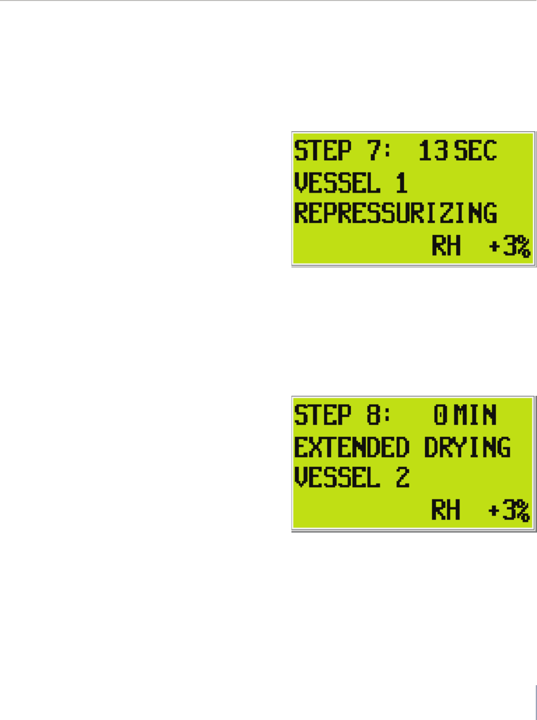
STEP SEVEN: Vessel 1 Repressurizing (241 - 300 seconds)
Vessel 1 (T1) purge exhaust pilot solenoid valve will de-energize,
causing Vessel 1 (T1) purge exhaust valve (V3) to close,
respressurizing Vessel 1 (T1).
The inlet tower selector pneumatic pilot valve maintains the
inlet valve (V1 & V2) positions.
STEP EIGHT: Vessel 2 Extended Drying
A few seconds before the end of repressurization, the
integrated Energy Management Purge Reduction System’s
moisture sensor determines the tower moisture load. If Vessel
2 (T2)’s moisture load is low enough, the tower will continue to
dry for an extended drying period until the moisture load has
reached a set high level or an additional 30 minutes, whichever
comes first. After 30 minutes, the unit will switch and continue
normal operation until the next extended savings step.
At the start of each extended savings step, the PLC checks for
faults, EMS relative humidity sensor value, and high outlet dew
point setting (optional) to ensure if the dryer needs to continue
drying. If so, the dryer will go into extended drying.
This feature reduces the overall purge consumption, saving
energy and money.

AHLD Series | Heatless Regenerative Desiccant Air Dryer
24
AIRCEL PROGRAMMABLE CONTROLLER (APC)
Main Screen Navigation
Control Menu Navigation
LEFT/RIGHT
LEFT/RIGHT
ALARM
SCREEN
MAIN
SCREEN
CONTROL
MENU
SETTINGS
MENU
LEFT/RIGHT
LEFT/RIGHT

Heatless Regenerative Desiccant Air Dryer | AHLD Series
25
Control Menu Operation
Settings Screen Operation
CONTROL
MENU
AIRCEL PROGRAMMABLE CONTROLLER (APC)
• Push OK to engage the menu
• Scroll to the desired selection and push OK
Settings Screen: For use with optional dew point display and high
humidity alarm
• To engage, push OK then scroll to the desired set point to be
changed.
• Push OK on the set point to be changed and use the up or down
arros to change the set point.
• Push OK to complete the change and ESC to de-select the screen.
Push ESC again to exit to the main screen or use the left or right
arrows to scroll to the next screen.

AHLD Series | Heatless Regenerative Desiccant Air Dryer
26
AIRCEL PROGRAMMABLE CONTROLLER (APC)
Time Control Main Navigation
This time cycle control menu allows the user to choose between a 10 minute standard time cycle and a shorter 5 minute cycle
for lower dew point option.
LEFT/RIGHT
SETTINGS
MENU
ANALOG
SCREEN
LEFT/RIGHT
Time Control Menu Operation
• To change the time cycle, push OK then scroll to the time cycle to
be selected. Push OK then push ESC.
• When changes are complete, push ESC to exit changes. Push ESC
again to return to the main screen.

Heatless Regenerative Desiccant Air Dryer | AHLD Series
27
Analog Screen Navigation
The analog screen simply displays the analog output signals.
Hours of Operation Screen Navigation
The hours of operation screen gives the user the amount of run time as well as the total amount of hours saved with the energy
management system.
LEFT/RIGHT
LEFT/RIGHT
TIME CONTROL
SCREEN
ANALOG
SCREEN
HOURS OF
OPERATION
ALARM
SCREEN
LEFT/RIGHT
LEFT/RIGHT
AIRCEL PROGRAMMABLE CONTROLLER (APC)

AHLD Series | Heatless Regenerative Desiccant Air Dryer
28
ALARM POP-UPS
• No Alarm: Alarm has been corrected
• Bad Probe: The EMS sensor has reached an out of range signal (check sensor and cable)
• High Outlet Dew Point (Option): Dew point has reached set point (check desiccant, pre-filters, control system)
• Failure to Shift (Option): Tower did not properly repressurize
AIRCEL PROGRAMMABLE CONTROLLER (APC)
Alarm Screen Navigation
LEFT/RIGHT
HOURS OF
OPERATION
MAIN MENU
LEFT/RIGHT

Heatless Regenerative Desiccant Air Dryer | AHLD Series
29
Alarm Pop-Up Screens
AIRCEL PROGRAMMABLE CONTROLLER (APC)
No Alarm: The normally closed state of the common alarm relay.
Drain Fault: Shows when the relative humidity (EMS) probe is out of range. This can be
either high out of range or low out of range. When this happens, the signal has either
been lost or the sensor may need to be replaced.
Bad RH Probe: Shows when the relative humidity (EMS) probe is out of range. This
can be either high out of range or low out of range. When this happens, the signal has
either been lost or the sensor may need to be replaced.
High Humidity Alarm: Alarm that is visible when the dew point is higher than the
set point. The set point for the high humidity alarm can be changed but it is not
recommended.
Bad Dew-P Probe: Alarm for the dew point sensor probe out of range. The out of range
can be either high or low. This can be either a complete loss of signal/voltage, the
resistor can be disconnected or the sensor may need to be calibrated.
The FTS Alarm (Failure-to-Shift): Alarm present when a vessel does not depressurize
correctly or if a vessel that is to be drying does not have pressure at or above a certain
set pressure.

AHLD Series | Heatless Regenerative Desiccant Air Dryer
30
TROUBLESHOOTING TABLE
Problem Probable Cause Remedy
High Dew Point
High inlet air ow Reduce inlet air ow
Inlet air temperature above design spec Reduce inlet air temperature to design spec
Poor pre-ltration Check pre-lter element, replace if needed
Inlet air pressure below design spec Increase pressure to the dryer
Desiccant contaminated Replace desiccant
Purge ow orice in the outlet APV valve may
be clogged
Dismantle outlet APV valve, and clean out the orice
Back pressure in regenerating chambers Muers are clogged, install new muers
Exhaust valve(s) not fully opening or closing
Check pilot valve and pilot air supply, dismantle and clean
exhaust valve, check ow control valve attached to purge
exhaust valve actuator may not be adjusted properly (should
be adjusted so exhaust valve opens within a 8-12 minute
time period)
APV valve leaking Dismantle and clean, replace seals and piston if needed
No input power Check that dryer is on with correct voltage
Controller failure Check, replace if needed
High Pressure
Drop
Low inlet pressure Increase inlet pressure to design pressure
Desiccant dusting High inlet ow velocities due to high ow
Inlet pre-lter dirty Inspect and replace as needed
High inlet ow rate Reduce inlet ow rate to meet dryer spec
Outlet lter dirty Inspect and replace as needed
Desiccant diuser screens clogged Inspect and clean as needed
High Back Pressure
in Regenerating
Tower
Purge muer clogged Clean and replace if needed
Desiccant diuser screens clogged Inspect and clean as needed
Restrictive purge exhaust piping Clean and replace with larger pipe if required

Heatless Regenerative Desiccant Air Dryer | AHLD Series
31
TROUBLESHOOTING TABLE
Problem Probable Cause Remedy
Dryer Fails to Shift
Towers
Exhaust valve(s) not functioning
Check pilot valve and pilot air supply, dismantle and clean
exhaust valve. Check ow control valve attached to purge
exhaust valve actuator may not be adjusted properly (should
be adjusted so exhaust valve opens within a 8-12 second
time period).
No input power Check that dryer is on with correct voltage
Controller failure Check, replace if needed
Pilot air supply restricted Check pilot lter, and pilot tubing restriction
Purge ow orice in the outlet APV valve may
be clogged
Dismantle outlet APV valve, and clean out the orice
Input APV valve malfunction Dismantle, clean, and reinstall
Outlet APV valve malfunction Dismantle, clean, and reinstall
Purge Failure
Purge muer clogged Remove and clean, replace if needed
Purge ow orice in the outlet APV valve may
be clogged
Dismantle outlet APV valve, and clean out the orice
Controller failure Check, replace if needed
Exhaust valve(s) not functioning
Check pilot valve and pilot air supply, dismantle and clean
exhaust valve purge exhaust valve actuator may not be
adjusted properly (should be adjusted so exhaust valve
opens within an 8-12 second time period). Check control
system.
Pressurization
Failure
Purge ow orice in the outlet APV valve may
be clogged
Reduce inlet ow rate to meet dryer spec
Exhaust valve(s) not functioning
Check pilot valve and pilot air supply, dismantle and clean
exhaust valve purge exhaust valve actuator may not be

AHLD Series | Heatless Regenerative Desiccant Air Dryer
32
2
.
Composition/information on ingredients
CAS Number
Content (W/W)
Chemical name
1333-84-2
>= 94.0 - <= 100.0 %
Aluminum oxide (Al2O3), hydrate
3
.
Hazard identification
Emergency overview
CAUTION: MAY CAUSE EYE, SKIN AND RESPIRATORY TRACT IRRITATION
.
May cause difficulty breathing
.
Prolonged or repeated contact may result in dermatitis
.
Contact with the eyes or skin may cause mechanical irritation
.
Contains material which may indicate/cause the possibility of sensory and pulmonary irritation
.
Avoid contact with the skin, eyes and clothing
.
Avoid inhalation of dusts
.
Use with local exhaust ventilation
.
Wear a NIOSH-certified (or equivalent) particulate respirator
.
Wear safety glasses with side-shields
.
Wear chemical resistant protective gloves
.
Wear protective clothing
.
Eye wash fountains and safety showers must be easily accessible
.
Potential health effects
Primary routes of exposure
Routes of entry for solids and liquids include eye and skin contact, ingestion and inhalation
. Routes of entry for
gases include inhalation and eye contact
.
Skin contact may be a route of entry for liquified gases
.
4
.
First-aid measures
If inhaled:
Keep patient calm, remove to fresh air
.
If necessary, give oxygen
.
If not breathing, give artificial respiration
.
Seek medical attention if necessary
.
Page: 1/5
(30286124/MDS_GEN_US/EN)
Company
BASF CORPORATION
100 Campus Drive
Florham Park, NJ 07932, USA
Safety data sheet
F200
Revision date : 2009/12/04
Version: 3.0
1
.
Substance/preparation and company identification
24 Hour Emergency Response Information
CHEMTREC: 1-800-424-9300
BASF HOTLINE: 1-800-832-HELP
APPENDIX
Desiccant Material Safety Data Sheet

Heatless Regenerative Desiccant Air Dryer | AHLD Series
33
6
.
Accidental release measures
Cleanup:
Vacuum up spilled product
.
Place into suitable container for disposal
.
7
.
Handling and storage
Handling
General advice:
Avoid dust formation in confined areas
.
Avoid contact with the skin, eyes and clothing
.
Ensure adequate
ventilation
.
Storage
General advice:
Keep container tightly closed in a cool, well-ventilated place
.
Storage stability:
Keep container dry.
8
.
Exposure controls and personal protection
Components with workplace control parameters
Aluminum oxide (Al2O3),
OSHA
PEL 5 mg/m3 Respirable fraction ; PEL 15 mg/m3 Total
hydrate
dust ;
ACGIH
TWA value 1 mg/m3 Respirable fraction ;
Safety data sheet
F200
Revision date : 2008/12/04
Version: 3.0
Page: 2/5
(30286124/MDS_GEN_US/EN)
If on skin:
After contact with skin, wash immediately with plenty of water and soap
.
Consult a doctor if skin irritation
persists
.
If in eyes:
In case of contact with the eyes, rinse immediately for at least 15 minutes with plenty of water
.
Immediate
medical attention required
.
If swallowed:
No hazards anticipated
.
If large quantities are ingested, seek medical advice.
5
.
Fire-fighting measures
Flash point:
Additional information:
Use extinguishing measures to suit surroundings
.
Hazards during fire-fighting:
No particular hazards known
.
Non-flammable.
Protective equipment for fire-fighting:
Wear self-contained breathing apparatus and chemical-protective clothing
.
NFPA Hazard codes:
Health : 0 Fire: 0
Reactivity: 1
Special:
APPENDIX
Desiccant Material Safety Data Sheet

AHLD Series | Heatless Regenerative Desiccant Air Dryer
34
APPENDIX
Desiccant Material Safety Data Sheet
Advice on system design:
Provide local exhaust ventilation to control dust
.
Provide local exhaust ventilation to maintain recommended
P.E.L
.
Personal protective equipment
Respiratory protection:
Wear a NIOSH-certified (or equivalent) particulate respirator
.
Observe OSHA regulations for respirator use (29
CFR 1910.134)
.
Wear appropriate certified respirator when exposure limits may be exceeded
.
Hand protection:
Wear chemical resistant protective gloves., Consult with glove manufacturer for testing data
.
Eye protection:
Safety glasses with side-shields
.
Body protection:
Body protection must be chosen based on level of activity and exposure
.
9
.
Physical and chemical properties
Safety data sheet
F200
Revision date : 2008/12/04
Version: 3.0
Page: 3/5
(30286124/MDS_GEN_US/EN)
Form:
Odour:
Colour:
pH value:
Melting point:
Boiling point:
Vapour pressure:
Density:
Bulk density:
Partitioning coefficient
n-octanol/water (log Pow):
Viscosity, dynamic:
Solubility in water:
10
.
Stability and reactivity
powder, granules, pellets, balls
odourless
off-white
9.4 - 10.1
2,050 °C
No data available
.
No data available
.
No data available
.
approx
.
650 kg/m3
38.0 - 52 lb/ft3
( 68 °F)
No data available
.
No data available
.
insoluble
Substances to avoid:
water
Hazardous reactions:
The product is chemically stable
.
Addition of water leads to increase in temperature
.
11
.
Toxicological information
Oral:
Information on: Aluminum oxide
LD50/rat: > 5,000 mg/kg (OECD Guideline 401)
----------------------------------

Heatless Regenerative Desiccant Air Dryer | AHLD Series
35
APPENDIX
Desiccant Material Safety Data Sheet
Information on: Aluminum oxide
Acute and prolonged toxicity to fish:
DIN 38412 Part 15 static
golden orfe/LC50 (96 h): > 500 mg/l
The product has not been tested
.
The statement has been derived from products of a similar structure and
composition
.
----------------------------------
Information on: Aluminum oxide
Acute toxicity to aquatic invertebrates:
OECD Guideline 202, part 1 static
Daphnia magna (48 h): > 100 mg/l
----------------------------------
13
.
Disposal considerations
Waste disposal of substance:
Dispose of in accordance with local authority regulations
.
Check for possible recycling
.
Disposal requirements are dependent on the hazard classification and will vary by location and the type of
disposal selected
.
All waste materials should be reviewed to determine the applicable hazards (testing may be necessary)
.
14
.
Transport information
Land transport
USDOT
Not classified as a dangerous good under transport regulations
Sea transport
IMDG
Not classified as a dangerous good under transport regulations
Air transport
IATA/ICAO
Not classified as a dangerous good under transport regulations
15
.
Regulatory information
Federal Regulations
Safety data sheet
F200
Revision date : 2008/12/04
Version: 3.0
Skin irritation:
Information on: Aluminum oxide
rabbit: non-irritant (OECD Guideline 404)
----------------------------------
12
.
Ecological information
Page: 4/5
(30286124/MDS_GEN_US/EN)

AHLD Series | Heatless Regenerative Desiccant Air Dryer
36
APPENDIX
Desiccant Material Safety Data Sheet
HMIS uses a numbering scale ranging from 0 to 4 to indicate the degree of hazard
.
A value of zero means that the substance
possesses essentially no hazard; a rating of four indicates high hazard
.
Local contact information
IMPORTANT: WHILE THE DESCRIPTIONS, DESIGNS, DATA AND INFORMATION CONTAINED HEREIN
ARE PRESENTED IN GOOD FAITH AND BELIEVED TO BE ACCURATE , IT IS PROVIDED FOR YOUR
GUIDANCE ONLY
.
BECAUSE MANY FACTORS MAY AFFECT PROCESSING OR APPLICATION/USE, WE
RECOMMEND THAT YOU MAKE TESTS TO DETERMINE THE SUITABILITY OF A PRODUCT FOR YOUR
PARTICULAR PURPOSE PRIOR TO USE
.
NO WARRANTIES OF ANY KIND, EITHER EXPRESSED OR
IMPLIED, INCLUDING WARRANTIES OF MERCHANTABILITY OR FITNESS FOR A PARTICULAR
PURPOSE, ARE MADE REGARDING PRODUCTS DESCRIBED OR DESIGNS, DATA OR INFORMATION
SET FORTH, OR THAT THE PRODUCTS, DESIGNS, DATA OR INFORMATION MAY BE USED WITHOUT
INFRINGING THE INTELLECTUAL PROPERTY RIGHTS OF OTHERS
.
IN NO CASE SHALL THE
DESCRIPTIONS, INFORMATION, DATA OR DESIGNS PROVIDED BE CONSIDERED A PART OF OUR
TERMS AND CONDITIONS OF SALE
.
FURTHER, YOU EXPRESSLY UNDERSTAND AND AGREE THAT
THE DESCRIPTIONS, DESIGNS, DATA, AND INFORMATION FURNISHED BY BASF HEREUNDER ARE
GIVEN GRATIS AND BASF ASSUMES NO OBLIGATION OR LIABILITY FOR THE DESCRIPTION,
DESIGNS, DATA AND INFORMATION GIVEN OR RESULTS OBTAINED, ALL SUCH BEING GIVEN AND
ACCEPTED AT YOUR RISK
.
END OF DATA SHEET
Safety data sheet
F200
Revision date : 2008/12/04
Version: 3.0
Registration status:
TSCA, US
OSHA hazard category:
Page: 5/5
(30286124/MDS_GEN_US/EN)
State RTK
MA, NJ, PA
released / listed
ACGIH TLV established
SARA hazard categories (EPCRA 311/312):
Acute
SARA 313:
CAS Number
1333-84-2
State regulations
State RTK
CAS Number
1333-84-2
Chemical name
Aluminum oxide (Al2O3), hydrate
Chemical name
Aluminum oxide (Al2O3), hydrate
16
.
Other information
HMIS III rating
Health: 1
Flammability: 0 Physical hazard:
1

Heatless Regenerative Desiccant Air Dryer | AHLD Series
37
APPENDIX
Electrical Schematic Drawings

AHLD Series | Heatless Regenerative Desiccant Air Dryer
38
APPENDIX
Main Power & PLC Input Drawings

Heatless Regenerative Desiccant Air Dryer | AHLD Series
39
APPENDIX
PLC Outlet & Sensor Drawings

AHLD Series | Heatless Regenerative Desiccant Air Dryer
40
APPENDIX
Back Panel Drawings
ITEMNUMBER PARTNUMBER DESCRIPTION QTY
1 AG3197201 BACKPLATEFITS14x 12 1
2 AG3948924 POWERSUPPLY,24VDC 1
3 AG3934769 POWERSUPPLY,5VDC 1
4 AG3251901 ANCHOR,SCREWEND,GRAY 6
6 AG3253101 TERMINALBLOCK,GRAY,J4 2
7 AG3253001 TERMINALBLK,GREEN/YELLOW ,J4 1
8 AG3933672 TERMINALBLOCK,BLUE,J3 4
9 AG3933345 TERMINALBLK,GRAY,J3 30
10 AG3948856 RELAY,SCREWTYPETERMINAL,SPDT 1
11 AG3182201 DUCT,WHITE,NARROWSLOT,1"X2" 3
12 AG3480590 COVER,WHITEDUCT,1" 3
13 AG3933346 TERMINALBLK,GREEN/YELLOW,J3 3
14 AG3948855 RELAY,SCREWTYPETERMINAL,DPDT 3

Heatless Regenerative Desiccant Air Dryer | AHLD Series
41
APPENDIX
Enclosure Layout Drawings
ITEMNUMBER QTY PARTNUMBER DESCRIPTION
50 1 AG3934778 EZDDISPLAY
51 1 AG3934775 EZDPROCESSOR
52 1 AG3934777 EZDI/O MODULE
54 1 AG3935996 ENCLOSURE,MODIFIED,14x12
55 1 AG3935091 SWITCH,PUSHBUTTON, ROUND
56 1 AG3935094 CONTACTBLOCKFORPUSHBUTTON
58 4 AG3935998 LIGHT,BLUE,6MM
59 2 AG3288701 MYERSHUBS
60 2 AG3342801 1/2XCLOSECONDUITNIPPLES
62 2 AG3101501 VA LVE,SOLENOID,3WAY,NEMA4
AHLD Series | Heatless Regenerative Desiccant Air Dryer
42
APPENDIX
Electrical Part Drawings
AHLDE‐SERIESELECTRICALDRAWING,AIRCEL
PROGRAMMABLE
CONTROLLER,NEMA‐4WITHENERGY
MANAGEMENT.
StockNumber StockDescription Quantity Spare?
AG3934778 EZDCONTROLLER,PROCESSOR 1 Y
AG3934775 EZDCONTROLLER,12DCINPUTS 1 Y
AG3934777 EZDCONTROLLER,CPU 1 Y
AG3935996 ENCLOSURE,MODIFIED,14X12 1 N
AG3935091 SWITCH,PUSHBUTTON,ROUND 1 Y
AG3935094 SWITCH,CONTACTBLOCK,FORALL 1 Y
AG3935095 LIGHT, FOR800BSWITCH,LED 1 Y
AG3935096 LENSFORPUSHBUTTON,GREEN 1 Y
AG3935998 LIGHT,PILOT,115V,8MM,BLUE 4 Y
AG3288701 HUB,MYERS,1/2" 2 Y
AG3342801 NIPPLE,CONDUIT ,1/2"XCLOSE, 2 N
AG3481168 STRAINRELIEF,3/8" 3 N
AG3481158 LOCKNUT,3/8" 3 N
AG3481159 RINGSEAL,3/8" 3 N
AG3948855 RELAY,SCREWTYPETERMINAL,DPDT 3 Y
AG3197201 PANE L,BACKPLATE,FITS14x12 1 N
AG3948924 POWERSUPPLY,24VDC 1 Y
AG3934769 POWERSUPPLY,5VDC 1 Y
AG3251901 ANCHOR,SCREWEN D,GRAY 6 N
AG3253101 TERMINALBLOCK,GRAY,J4 2 N
AG3253001 TERMINALBLOCK,GREEN/YELLOW,J4 1 N
AG3933672 TERMINALBLOCK ,BLU,J3 4 N
AG3933345 TERMINALBLOCK,GRAY,J3 30 N
AG3948856 RELAY,SCREWTYPETERMINAL,SPDT 1 Y
AG3182201 DUCT,WHITE,NARROWSLOT,1x2 3 N
AG3101501 VALVE,SOLENOID,3WAY,NEMA4,1/4" 2 Y
AG3933346 TERMINALBLK,GREEN/YELLOW,J3 3 N
AG3480590 COVER,WHITEDUC T,1" 3 N
AG3481460 CORD,SJEEO W,18/3 10 N
AG3480463 WIRE#18,BLUE 80 N
AG3480947 WIRE#18,RED 98 N
AG3480948 WIRE#18,WHITE 17 N
AG3480991 WIRE#18,WHITE/BLUE 9.5 N
AG3373901 WIRE#16,ORANGE 6 N
AG3372301 WIRE#16,GREEN 12 N

Heatless Regenerative Desiccant Air Dryer | AHLD Series
43
SERVICE NOTES
DATE SERVICE PERFORMED NOTES

AHLD Series | Heatless Regenerative Desiccant Air Dryer
44
SERVICE NOTES
DATE SERVICE PERFORMED NOTES

Heatless Regenerative Desiccant Air Dryer | AHLD Series
45
SERVICE NOTES
DATE SERVICE PERFORMED NOTES

AHLD Series | Heatless Regenerative Desiccant Air Dryer
46
SERVICE NOTES
DATE SERVICE PERFORMED NOTES

Heatless Regenerative Desiccant Air Dryer | AHLD Series
47
WARRANTY
Desiccant Air Dryers
(1 Year Limited Warranty Coverage)
Standard desiccant air dyrers come with a limited one year
warranty covering parts and labor.
NOTE: Any unit shipped to us without prior return
authorization will be refused.
WARRANTY PARTS COVERAGE
• Exhaust valves (all models)
• Wafer check valves (800 - 5,000 scfm models)
• Heater
• Blower
• Control board (all heatless models)
• Programmable controller (all heat regenerative models)
• Automatic pisto valves
• Control solenoids
• Re-pressurization valves
• Depressurization valves
• Electrical components (temperature and over-temperature
controllers)
• Instrumentation (air and dierential pressure gauges,
temperature gauges)
SERVICE COVERAGE
• Parts supplied by us to dealer, authorized service repair
center, or job site (end user). See note 5 on page 6.
• Labor provided by us, dealer, authorized service repair
center, or factory.
Zero Loss Drains
(1 Year Limited Warranty Coverage)
COVERAGE
• Parts supplied by us to dealer, authorized service repair
center, or job site (end user). See note 5 on page 6.
• Labor is not covered by our warranty. Customer is
responsible for all labor.
NOTES:
1. Aircel reserves the right to require units to be shipped
back to the factory for proper repair if it deems necessary.
We will make return freight arrangements in this instance.
Aircel warranty will only cover freight charges for
shipments within the continental United States.
2. Warranty does not cover the removal & installation of a
dryer(s) or parts within its warranty period or beyond.
3. Desiccant is not covered under warranty. The average
life expectancy of desiccant is 3 to 5 years when proper
maintenance is performed.

Aircel, LLC.
323 Crisp Circle
Maryville, TN 37801
Parts and Service
For genuine Aircel replacement parts, call:
800.767.4599
For faster service, please have unit’s
model and serial number, part number, or
description.
AircelDryers.com
