
AHLD Series | Heatless Regenerative | 70 - 4,000 scfm
DESICCANT DRYER USER MANUAL
The information in this manual is current as of its publication date and applies to AHLD Series desiccant air dryers until next revision of this manual.
Copyright © January 2017 Aircel, LLC. All rights reserved.
WARRANTY NOTICE
Failure to follow the instructions
and procedures in this manual, or
misuse of this equipment, will void its
warranty.
WARNING!
Users are required to read the entire
User Manual before handling or using
the product. Keep the User Manual in
a safe place for future reference.

| AHLD Series Manual
Desiccant Air Dryer User Manual
ii
DRYER DATA SHEET
Model Number: Serial Number:
Date of Manufacture:
Ship Date: Installation Date:
Customer Address:
Customer City: State/Zip:
Other:

AHLD Series Manual |
Desiccant Air Dryer User Manual
iii
TABLE OF CONTENTS
Section 1: Safety 1
1.1 Introduction 1
1.2 Safety Signal Words 1
1.3 General Safety Procedures 1
1.4 Safe Operating Procedures 2
1.5 Desiccant Safety Precautions 2
1.5.1 Desiccant First Aid Recommendations 2
1.6 Implementation of lockout/tag-out 2
1.6.1 Procedures 2
1.6.2 General Security 3
Section 2: Description 4
2.1 Introduction 4
2.2 System 4
2.3 Standard Features 5
2.4 Additional Options 5
Section 3: Installation 6
3.1 Inspection on Arrival 6
3.2 Lifting Information 6
3.3 Installation Codes and Procedures 7
3.4 Locating and Installing the Dryer 7
3.5 Preliminary Start-Up Checklist 9
Section 4: Operation 11
4.1 Operating Procedures 11
4.2 Short-Term Shut Down 11
4.3 Short-Term or Long-Term Shut Down 12
4.4 Shut Down Emergency 12
Section 5: Controllers 13
5.1 System Navigation 13
5.2 Dryer Operation Screens 14
5.3 Navigation 18
Section 6: Maintenance 26
6.1 Introduction 26
6.2 Maintenance 26
6.2.1 Daily 26
6.2.2 Weekly 27
6.2.3 Semi-Annual 27
6.2.4 Annual 27
6.3 Desiccant Replacement 27
Section 7: Troubleshooting 29
7.1 Introduction 29
7.2 Initial Checks 30
7.3 AHLD Series Troubleshooting Guide 31
Appendix A: Specifications 33
A.1 Table of Specifications - AHLD Series 33
Appendix B: Material Safety Data Sheets 34
B.1 Activated Alumina Desiccant 34
Appendix C: Drawings 39
C.1 Electrical Schematic Drawings 39
C.2 Main Power & PLC Input Drawings 40
C.3 PLC Outlet & Sensor Drawings 41
C.4 Back Panel Drawings 42
C.5 Enclosure Layout Drawings 43
C.6 Electrical Part Drawings 44
Service Notes 45
Warranty Information 51


AHLD Series Manual |
Desiccant Air Dryer User Manual
1
1.1 Introduction
Thank you for purchasing Aircel’s AHLD E-Series Heatless
Regenerative Desiccant Air Dryer with integrated Energy
Management Purge Reduction System. To ensure maximum
performance and safe operation of an Aircel desiccant dryer
covered by this manual, everyone involved with the dryer’s
installation, operation, and maintenance must read and
carefully follow the instructions in this manual.
Misuse or modification of this equipment may result in
personal injury. Do not misuse or modify. The high efficiency
heated regenerative desiccant dryer is used exclusively for
purifying compressed air in non-hazardous locations.
The state-of-the-art system is designed and constructed
in accordance with the rules and regulations regarding
adsorption technology and industrial safety. There are
hazards accompanying this type of product if not operated
for the intended purpose by trained and specialized
personnel.
1.2 Safety Signal Words
Throughout this manual, signal words are present to advise
of safety precautions and/or standard practices. Obey these
signal words as dened below:
DANGER! - Indicates an imminently hazardous situation
which, if not avoided, will result in death or serious injury.
WARNING! - Indicates a potentially hazardous situation
which, if not avoided, could result in death or serious injury.
CAUTION! - Indicates a potentially hazardous situation
which, if not avoided, may result in minor or moderate
injury.
NOTICE - used to address practices not related to personal
injury.
1.3 General Safety Procedures
• Electrical work must conform to the specifications
indicated by Aircel and any local or state laws that may
apply.
• Personnel must wear appropriate safety gear before
working on any electrical or mechanical aspects of the
machine.
• Appropriate tools have to be used for all installation and
maintenance work. If special tools are required and are
not available to the installation crew, contact the factory
or your Aircel representative.
• A copy of the Operation Manual must be made available
to all personnel involved with the installation, operation,
and maintenance of the equipment.
• Before performing any maintenance operations on
the equipment, the unit must be shut down, isolated,
electrical power removed, and completely depressurized.
• To ensure compatibility and continued trouble free
operation, only genuine Aircel parts must be used.
• DO NOT make any constructional changes to the unit.
Only Aircel or its authorized representatives with the
prior approval can perform any constructional work on
the machine.
• DO NOT use foreign parts.
• DO NOT use compressed air from the dryers for
breathing purposes - install a breathing air package to
ensure conformance with OSHA regulations.
• DO NOT disable or disengage any protective equipment
used on the machine.
NOTICE
For optimum performance, use only Aircel replacement
parts.
SECTION 1: SAFETY
CAUTION!
Misuse / modication hazard
Misuse or modication of this equipment may result
in personal injury.
Do not misuse or modify this equipment under any
conditions.

| AHLD Series Manual
Desiccant Air Dryer User Manual
2
1.4 Safe Operating Procedures
• Pressurize and depressurize compressed air SLOWLY!
Always open air valves slowly when pressurizing the airline
system or equipment. Repair air slowly when depressurizing
your air system or equipment.
• Circuit breakers, fusible disconnect, and wiring should
conform to national and/or local electrical codes. Make
certain that qualified electrical personnel perform the
electrical installation for this unit.
• Only use original fuses for the rated voltage and current.
• Shut down the unit in the correct recommended procedure.
• Before any work on system, always depressurize the unit
and remove all electrical power.
• After shut down, put up warning notice to prevent the unit
from being switched “ON” accidentally.
• Inspect all piping, hoses, and connections. Make sure that
all hoses are in good condition and are rated for the correct
working pressure. Do not allow hoses to come into contact
with oils, chemicals, or sharp objects.
• Secure condensate drain lines. Unsecured, flexible drain
lines may whip violently under pressure and may cause
bodily harm.
1.5 Desiccant Safety Precautions
1.5.1 DESICCANT FIRST AID RECOMMENDATIONS
1.5.1.1 INHALATION
Use a contoured dust mask during loading and unloading
operations. If high concentrations are inhaled, immediately
move to fresh air. Keep person calm. If not breathing, give
articial respiration. If breathing is dicult, give oxygen. Call a
physician.
1.5.1.2 SKIN CONTACT
In case of contact, immediately flush skin with plenty of soap
and water for at least 15 minutes.
1.5.1.3 EYE CONTACT
In case of contact, immediately flush eyes with plenty of water
for at least 15 minutes. Call a physician.
1.5.1.4 SPILLS
Clean accidental spills by vacuuming, sweeping, or flushing to a
sewer treated for suspended solids. Avoid creating excess dust.
1.6 Implementation of lockout/tag-out
The energy control procedure denes actions necessary to
lockout a power source of any machine to be repaired, serviced,
or set-up, where unexpected motion, or an electrical or other
energy source, would cause personal injury or equipment
damage. The power source on any machine shall be locked
out by each employee doing the work except when motion is
necessary during setup, adjustment, or troubleshooting.
1.6.1 PROCEDURES
The established procedures for the application of energy control
shall cover the following elements and actions and shall be
initiated only be Authorized Persons and done in the following
sequence:
1. Review the equipment or machine to be locked and tagged
out.
2. Alert operator and supervisor of which machine is to be
worked on, and that power and utilities will be turned o.
3. Check to make certain no one is operating the machine
before turning power o.
4. Turn o the equipment using normal shut-down procedure.
5. Disconnect the energy sources:
a. Air and hydraulic lines should be bled, drained, and
cleaned out. There should be no pressure in these lines
or in the reservoir tanks. Lockout or tag lines or valves.
WARNING!
Inhalation, Skin, & Eye Irritant
The desiccant used in this equipment is not considered
hazardous. Contact with and disposal of desiccant
must be in accordance with the relevant MSDS and
all local codes and regulations. The following lists the
more common safety measures to be observed during
loading and unloading operations. Reference the
MSDS in the appendix for complete safety measures.

AHLD Series Manual |
Desiccant Air Dryer User Manual
3
b. Any mechanism under tension or pressure, such as
springs, should be released and locked out or tagged.
c. Block any load or machine part prior to working under it.
d. Electrical circuits should be checked with calibrated
electrical testing equipment and stored energy and
electrical capacitors should be safely discharged.
6. Lockout and/or tag out each energy source using the
proper energy isolating devices and tags. Place lockout
hasp and padlock or tag at the point of power disconnect
where lockout is required by each person performing work.
Each person shall be provided with their own padlock and
have possession of the only key. If more than one person is
working on a machine, each person shall ax personal lock
and tag using a multi-lock device.
7. Tag-lock devices shall be used only when power sources
are not capable of being locked out by use of padlocks and
lockout hasp devices. The name of the person axing the
tag to power source must be on tag along with date tag was
placed on power source.
8. Release stored energy and bring the equipment to a “zero
mechanical state.”
9. Verify isolation: Before work is started, test equipment to
ensure power is disconnected.
1.6.2 GENERAL SECURITY
1. The lock shall be removed by the Authorized Person who
put the lock on the energy-isolating device. No one other
than the person/persons placing padlocks and lock out
hasps on power shall remove padlock and lockout hasps
and restore power. However, when the authorized person
who applied the lock is unavailable to remove it, her or his
Supervisor may remove padlock(s) and lock out hasp(s) and
restore power only if it is rst:
a. veried that no person will be exposed to danger..
b. veried that the Authorized Person who applied the
device is not in the facility.
c. noted that all reasonable eorts to contact the Authorized
Person have been made to inform her or him that the
lock out or tag out device has been removed.
d. ensured that the Authorized Person is notied of lock
removal before returning to work.
2. Tag out system - Tags are warning devices axed at points
of power disconnect and are not to be removed by anyone
other than the person placing tag on power lockout. Tags
shall never be by-passed, ignored, or otherwise defeated.

| AHLD Series Manual
Desiccant Air Dryer User Manual
4
2.1 Introduction
Untreated compressed air contains many contaminants such
as water, compressor oil, pipe scale, and contamination from
ambient air. All these contaminants cause excessive corrosion,
erosion, freezing, and regenerative type dryer system with all
recommended filtration will remove these contaminants to
harmless levels. The end result is that instruments that come
in contact with the dry compressed air stay clean and do not
corrode, therefore lasting much longer. Products that may
come in contact with clean, dry, compressed air are virtually
unaffected. Therefore, rejection rates are reduced.
2.2 System
Moisture saturated compressed air enters the coalescing
pre-filter, where aerosols are coalesced then drained via an
automatic drain system.
The moist water vapor-laden inlet air free of liquid water flows
to the inlet of the dryer through the APV (Automatic Piston
Valve) (A), which diverts the inlet air to one of the towers - in
this example, Tower 1.
Air flows upward through the adsorbent bed removing the
moisture vapor; the dried airflow exits the tower through the
outlet valve (B), flowing to the outlet particulate after filter,
which removes particulates from the air stream. Clean and dry
air now flows to the customer process air distribution system.
As one tower is drying air, the other tower will be regenerating
(purging) the adsorbent bed. In this example, Tower 2 will be
regenerating. Prior to regeneration, the exhaust valve (C) is
opened and the tower is depressurized to near atmospheric
pressure, the tower will now be regenerating. During the
regenerating process, a small portion of dry outlet compressed
air is used, 15% on average based on standard design capacity
of 100 psig, 100°F inlet air, 100°F ambient air, and pressure
dew point of -40°F.
The dry regeneration airflow is channeled through the outlet
orifice to the regenerating tower, removing moisture from
the adsorbent bed and exits the regenerating tower through
exhaust valve (C) and exhaust muffler to ambient. After
regeneration cycle is complete, valve (C) closes, causing Tower
2 to repressurize to line pressure.
Next, the tower will switch when exhaust valve (D)
opens, causing Tower 1 to depressurize and regenerate.
Simultaneously, the inlet and outlet APV valves (A) will shift the
pistons to the low pressure Tower 1, causing the inlet airflow
to be diverted to Tower 2, which will now be the drying tower.
This switching process will continue repeatedly.
The dryer control system is completely automatic and cycles
the system through the drying and regeneration cycles. The
standard cycle drying time is 5 minutes, regeneration cycle is
4 minutes, and repressurizing cycle is 1 minute.
The Aircel AHLD E-Series Heatless Dryer incorporates a unique
energy saving control system to reduce purge air loss with its
integrated Energy Management Purge Reduction System. This
system utilizes a moisture sensor sampling the air from mid-
bed of the on-stream drying tower, after the fixed purge time
is complete, the regenerating/purging tower will repressurize.
If the moisture sensor senses a low moisture condition or low
load in the drying tower, the drying tower will remain in the
drying mode after the fixed drying time cycle for an extended
period of time. The end result is an overall purge reduction
and significant energy savings.
A
D
B
C
D
Pre-Filter
Tower 1 Tower 2
After Filter
FIGURE 2-1: TYPICAL SCHEMATIC FLOW DIAGRAM
AHLD Series 70 - 4,000 scfm rated model
SECTION 2: DESCRIPTION

AHLD Series Manual |
Desiccant Air Dryer User Manual
5
2.3 Standard Features
• Integrated Energy Management Purge Reduction
System for ecient energy savings and reduced cost of
operation.
• Optimal tower size for low velocities reducing desiccant
uidization, and high contact time for ecient low dew
point performance.
• Tower pressure relief valves.
• Standard design capacity based on 100 psig, 100°F inlet
air, 100°F ambient air, and Pressure dew point of -40°F.
• Purge exhaust muers for quiet operation.
• Tower pressure gauges for additional visual operation of
dryer operation.
• Stainless steel desiccant supports and air diusers to
prevent channeling.
• Counter-current reactivation for ecient desiccant
regeneration.
• PLC Controlled Electrical System
• Adjustable (5 min., 10 min.) cycle times: 10 minute cycle
for the standard -40°F Pressure dew point outlet dew
point systems, 5 minute cycle used in the optional -100°F
Pressure dew point outlet dew point systems.
• Controlled repressurization to slowly repressurize the
regenerated vessel to line pressure prior to switch over
preventing desiccant bed movement and attrition.
• Fail safe design: Failure of power and/or pilot air causes
the purge exhaust valves to close, eliminating loss of air
pressure. The system also provides uninterrupted drying
air ow, preventing a dead heading eect.
• Control pilot air lter provides clean air to air control
system for long trouble-free reliable operation.
• Desiccant towers are designed, fabricated, and stamped
according to ASME code.
• Desiccant ll and drain ports for ease of desiccant
replacement.
• Structural steel frame.
• Highly reliable non-lubricated air inlet and outlet valves
(APV) Automatic Piston Valve (AHLD 70 E - AHLD 750 E)
and high performance, non-lubricated buttery valves
(AHLD-1000 E - AHLD-1500 E).
• Highly reliable angle seat design purge exhaust valves.
• Tower operating LED status lights (left and right tower
dryer, left and right tower regenerating).
• On/O switch and power On light.
• NEMA 4 weather resistant electrical system construction.
2.4 Additional Options
• -100°F outlet pressure dew point.
• Failure-to-shift alarm with pressure transducers.
• Outlet dew point sensor with dew point readout on
system display.
• High humidity alarm.
• Outlet dew point 4-20 ma signal.
• Mounted, piped, and wired ltration packages.

| AHLD Series Manual
Desiccant Air Dryer User Manual
6
3.1 Inspection on Arrival
All regenerative desiccant dryers are tested and operated
before shipment. However, shipping vibration may cause
damage such as loosening of certain parts. To ensure smooth
installation, it is recommended that immediately upon receipt
of the unit, the system is checked for the following:
1. Inspect unity on delivery.
2. Report any damage to the delivery carrier.
3. Request a written inspection report from the Claims
Inspector to substantiate the claim.
4. File claims with the delivery carrier.
5. Compare unit received with description of product ordered.
Check the serial plate label and make sure that it is the
correct Model was ordered. Note the equipment Capacity
and Power Supply requirements and ensure that they are in
accordance with your specifications. The rated conditions
of the dryer are indicated on the serial plate label. If there
is any discrepancy, contact your representative listed on
the manual back cover.
6. Vibration during shipping can loosen the connections.
Inspect all pipe and tubing and make sure they are all
tightened and secured.
7. Report incomplete shipments to the delivery carrier and
your service representative.
3.2 Lifting Information
1. Use all lifting points provided. Special care must be used
when lifting the dryer to prevent tip-over.
2. Use clevis connectors, not hooks, on lifting slings.
3. Only lift unit under support frame/base by using the fork
lift openings provided. Do not lift by piping.
4. Check the approximate weight provided on the specification
control drawing to ensure adequate lift truck capacity.
5. Allow only qualified operators to lift the equipment.
6. Refer to applicable OSHA regulations and local codes when
using cranes, forklifts, and other lifting equipment.
SECTION 3: INSTALLATION
WARNING!
Lifting Hazard
Failure to lift the unit correctly can result in severe
personal injury or property damage.
• Use appropriate lifting equipment and adopt
all safety precautions needed for moving and
handling the equipment.
• A forklift, or crane is recommended for unloading
and installation.
• Lift unit by lifting lugs and frame only. Do not lift
by piping.

AHLD Series Manual |
Desiccant Air Dryer User Manual
7
3.3 Installation Codes and Procedures
• Safe and efficient operation of the unit depends on proper
installation.
• Authorities with jurisdiction should be consulted before
installing to verify local codes and installation procedures.
In the absence of such codes, install unit according to the
National Electric Code and NFPA No. 70-latest edition.
• A qualified installation and service agent versed in all
regulatory codes must complete installation of this unit.
• All shipping materials, including shipping covers, must be
removed from the unit prior to, or during, unit installation.
3.4 Locating and Installing the Dryer
1. Locate unit on a level foundation. Dryer should be mounted
on a suitably structured flat and level floor or base that is
free from vibration.
2. Before bolting dryer skid to the foundation, shim skid(s) as
needed. Additional mounting clip angles can be attached to
base frame for ease of bolting to foundation, if necessary.
The frame(s) must be securely bolted to the foundation
to prevent movement resulting from earth tremors and
induced piping vibration.
3. Make certain all shipping materials have been removed
such as crating, plastic wrap, fitting covers, etc.
4. Install unit to provide adequate clearance for maintenance
services. Dryer and accompanying filters should be installed
with at least three (3) feet clearance from the adjoining
walls to provide easy access for routine maintenance and
adequate air flow.
6. Unit should be located in a weather protected area with
an ambient temperature range between 40 - 100°F. In
conditions where the ambient drops below freezing, Aircel
recommends the use of heat trace on any coalescing filter
sumps and drain lines and the use of heated type drains.
7. Install flanges, fittings, and piping on system using the
correct pipe size and pressure rating. See drawing package
provided with the unit. Connect dryer wet air inlet to the
flange attached to the inlet pre-filter with the automatic
condensate drain on the bottom of the filter bowl. This
typically runs to the bottom of the dryer vessels. Connect
dry air outlet to plant process to the flange attached to
the outlet after-filter with a manual drain/vent valve on
the bottom of the filter bowl. Dryer outlet piping to filter is
typically from top of dryer.
8. Optional system configuration: Install a dryer bypass or
isolation valve to allow isolation of the dryer for service and
maintenance without interrupting the compressed air flow.
9. Provide adequate power supply. See rating and
specification information on dryer data label and drawing
package information. Make certain dryer system is properly
grounded.
10. It is recommended to supply power to the dryer through a
WARNING!
Electric Shock Hazard
This machine is connected to high-voltage power,
which can cause severe electrical shock and injury.
• Follow proper lock out/tag out procedures before
performing service or maintenance work.
• Electrical installation must be performed by a
qualied electrician and comply with all applicable
national and local codes.
WARNING!
Inappropriate tools hazard
Using inappropriate tools for installation or
maintenance work can lead to personal injury or
property damage.
Appropriate tools must be used for all installation and
maintenance work.
CAUTION!
Moisture contamination hazards
Air supplied while the regenerative desiccant dryer is
bypassed will be wet and saturated. Some downstream
processes may not tolerate this air supply due to the
risk of contamination of sensitive equipment.
NOTICE
Adequate sealing
The bypass system valves require bubble tight sealing.

| AHLD Series Manual
Desiccant Air Dryer User Manual
8
customer-supplied disconnect switch to remove all power
to the dryer system.
11. The regeneration air outlet (typically located at the back
of the dryer on the bottom line between the vessels)
should be piped away from all equipment and occupied
spaces. The pressure loss through the regeneration outlet
piping should not exceed two (2) inches of water column
to prevent excessive back pressure on the blower. If the
regeneration outlet line is to be piped upwards, a manual
drain valve must be installed at the lowest point to drain
any liquid water.
12. Connect any remote dry alarm contacts to control room or
signaling device to warn of dryer malfunction. Refer to the
electrical schematic for connections.
13. The dryer relief valves are designed and sized to relieve
excess pressure resulting from the thermal expansion
of air trapped in the vessels in the event the vessels are
subjected to heat, such as in a conflagration. Valves are set
to relieve at the maximum design pressure of the desiccant
vessels.
14. It is recommended to have manual vent valves in strategic
locations to aide in depressurizing the system for repair or
maintenance.
15. Ensure the dryer towers are filled with desiccant. Larger
dryers may have desiccant shipped separately; in which
case, the media has to be filled into the pressure vessels
from the desiccant fill ports at top of each vessel. Care
must be taken when filling the media and must be done
gradually to prevent powdering.
16. Install the Aircel inlet compressed air particulate pre-
filter drain to an open drain system for safety and to
prevent puddling of water at dryer system area. Piping
should be secured and angled slightly downward to drain
condensate. Drain system must have a vented air gap to
prevent a pressurized condition.
17. If there are any changes in the operating conditions of
the system from those published in this manual, contact
Technical Support at the number published on the back of
this manual.
WARNING!
Unsafe personnel conditions hazard
Keep personnel safely away from desiccant dryer relief
valves. In the event of discharge, the relief valves can
cause an unwanted condition or hazard to personnel.
Some discharge ports could be piped to a safe location.
Drain
Valve
Air or Water
Cooled
Condenser
Air
Compressor
Drain
Valve
Dry Air
to Plant
Drain
Valve
Drain
Valve
After Filter
Pre-Filter
Separator
FIGURE 3-1: Typical Installation Setup
NOTICE
Refer to system data label and/or drawing package for
desiccant media type and quantity per each vessel.

AHLD Series Manual |
Desiccant Air Dryer User Manual
9
3.5 Preliminary Start-Up Checklist
In addition to the below notes, cautions and warnings, refer
to the previous sections on General Safety Procedures, Safe
Operating Procedures and any safety procedures required by
end user.
CAUTION!
Follow local codes
Before connecting condensate to open drainage
system make certain this is allowed, user or local
codes may require treatment before discharging into
drain system.
NOTICE
• Refer mechanical drawing, electrical drawing,
ow diagram, and the display screen shots and
descriptions located in this manual for reference.
• It is recommended to have isolation valves before
and after the dryer to maintain low dew point
when system is not in use in use.
• It may take days to a few weeks of operation to
stabilize the system and produce the specied
dew point. Some customer processes may not
tolerate a higher dew point air supply. DO NOT
use the outlet air from the system until the air
meets the customer’s system requirements.
• During transport and storage of the equipment,
desiccant can become preloaded with atmospheric
moisture and cause poor outlet dew point.
Regenerate both desiccant beds before placing the
dryer in service to avoid contaminating sensitive
downstream systems with higher moisture
concentration. Installation must be complete and
process air available to regenerate the desiccant
beds.
WARNING!
• Tower/vessel relief valves are set from
manufacturer. DO NOT adjust these valves.
• Always pressurize and depressurize the system
slowly.
• This system must be operated or serviced by
qualied persons familiar with pressurized
systems and electrical controls.
• Before servicing any component make certain the
system is depressurized and de-energized.
• Hearing protection is recommended for personnel
protection when the system is in operation and/
or pressurized in order to protect from any loud
bursts of pressurized air to atmosphere. This can
occurs through the depressurization and purge
exhaust muers, vent ports, and lter drain ports.
• Eye protection safety glasses are recommended
for personnel protection when the system is in
operation and/or pressurized in order to protect
from possible ying debris expelled from the
purge exhaust muers during tower, vent, or
drain depressurization or any other possible ying
debris.
• The dryer must not be subjected to low operating
pressures for an extended period of time.
Extremely high velocities in the desiccant bed
would cause serious attrition of the desiccant and
possible rupture the lter elements. Some control
over the ow through the desiccant dryer on start-
up must be exercised.
• Do not use the dryer without the inlet lter
element or outlet lter element.
• Do not use the dryer without the vessel desiccant
media in place.
• DO NOT turn dryer power on until instructed.
• Make certain air inlet and air outlet are connected
correctly.
• Make certain the power supply is connected to the
system properly.

| AHLD Series Manual
Desiccant Air Dryer User Manual
10
1. Check the inlet and outlet connections are the correct size,
pressure rating, and tightened securely.
2. Ensure the inlet air line is connected to the inlet pre-filter
with automatic drain valve (typically, the inlet piping flows
from inlet pre-filter to bottom of vessels).
3. Ensure the dry outlet air is connected to the outlet after
filter with the manual drain valve which is piped from top
of vessels to outlet after filter.
4. Check that the correct power supply is connected to the
desiccant air dryer system with an adequate disconnect
switch.
5. Check that all manual valves are in correct open and
closed positions and that compressed air is available to be
supplied to the desiccant air dryer system.
a. Dryer system block and bypass valving (if applicable):
Initially, dry air outlet isolation block valve should be
closed, and the inlet isolation block valve should be
closed. If a bypass valve is used in system and customer
can tolerate wet air into process for a short amount of
time, the bypass valve can be slowly opened to allow air
into customer process system.
b. Inlet coalescing pre-filter automatic drain isolation valve
should be open.
c. If a manual vent/drain valve is used near the inlet
coalescing pre-filter automatic drain valve to ambient,
this valve should be closed. (This inlet pre-filter manual
drain valve is used in some systems in case of automatic
drain valve failure.)
d. Outlet particulate after filter manual drain/vent valve
should be in closed position.
e. Any filter differential pressure gauge isolation valves
should be in open position.
f. Any pressure gauge isolation valves should be in open
position.
6. With the customer-supplied compressed air to the system,
OPEN the inlet valve slowly (two to three minutes) to
gradually pressurize the system. Do not open valve too
quickly. Opening valve and suddenly pressurizing the
system can cause damage to the dryer heat exchanger and
other components.
7. Check the complete dryer system for leaks. If found, repair
all leaks and re-test.
8. Check the control pilot air pressure is set to between
80 - 100 psi. Typical setting is 100 psig; adjust control air
pressure regulator if needed.
9. Turn on the customer-supplied main disconnect switch
and verify correct voltage to dryer electrical panel.
10. Near the dryer outlet (APV) valve, check the control air/
pilot air regulator secondary pressure, the regulator gauge
should read 100 psig. Increase or decrease regulator
knob to achieve a 100 psig control air secondary pressure
reading.
11. Make certain the purge exhaust valves slowly open within
an 8 to 12 second time period, some adjustment of
the flow control valve attached to the actuator may be
required, after adjustment tighten down the locking collar.
12. Make certain a slight amount of air flow is felt at the end
of the EMS RH sensor sample cell exhaust coil tube (this is
normally located at the back of the dryer) adjust the needle
valve to give more or less flow.
13. Check the operation of several cycles completely by
following the control panel display screen operation, the
panel lights on the electrical box, and the tower pressure
gauges to make certain the dryer system is operating as
displayed. Also refer to the how it works section, flow
diagram, electrical drawing, dryer control display screen
descriptions, and sequence of operation in this manual for
reference.
14. After the preliminary start up checklist has been completed,
system as been verified, and outlet dew point is at an
acceptable low level, the compressed air outlet isolation
valve on the dryer system can now be slowly opened to
supply clean dry compressed air to the facility.
15. Make certain a slight amount of air flow is felt at the end
of the EMS RH sensor sample cell exhaust coil tube (this is
normally located at the back of the dryer) adjust the needle
valve to give more or less flow.
16. Review the dryer system display screen shots (in this
manual) to make certain the parameters are set as needed
in the customer dryer.
17. Purge air flow is preset and not adjustable.
18. After approximately one to two weeks of service, replace
the depressurization mufflers. New systems may have
more desiccant dusting and cause the mufflers to become
clogged, which could cause a depressurization or muffler
failure. Check flange bolts for tightness, torque as needed.

AHLD Series Manual |
Desiccant Air Dryer User Manual
11
4.1 Operating Procedures
After the initial startup, the dryer operation is completely
automatic. To understand the details of the operation, see
Figure 2-1: Typical Schematic Flow Chart on page 4.
4.2 Short-Term Shut Down
(For Maintenance)
The desiccant air dryer system can be shut down at any time.
Some systems may have a customer supplied bypass valve.
This can be slowly opened to allow air downstream.
• If applicable, slowly open the bypass valve.
• Slowly close the outlet shut off valve.
• Slowly close the inlet shut off valve.
• To depressurize the dryer after the dryer is isolated, turn
the power on. A purge exhaust valve will open and the
dryer system starts to depressurize. The manual vent valve
on the outlet after filter can be opened to depressurize the
dryer until the tower pressure gauges read 0 psig.
• Next, turn on power off/on switch to off position at the
dryer system electrical enclosure.
• Disconnect main electrical power supply to dryer system by
switching the upstream electrical power supply disconnect
to the off position.
SECTION 4: OPERATION
WARNING!
Electric Shock Hazard
This machine is connected to high-voltage power,
which can cause severe electrical shock and injury.
• Follow proper lock out/tag out procedures before
performing service or maintenance work.
• When the system is shutdown and power removed,
lock out power supply and depressurize system
before performing maintenance or service work
to avoid injury to personnel or property damage.
WARNING!
• Some circuits may be still be active or have voltage
even with main power disconnect in o position
such as, the dryer customer alarm contacts which
may have a separate external power source
connected to the dryer alarm contacts.
• If possible, remove any external power sources to
electrical enclosure
• Always remove ttings slowly in case some residual
pressure is remaining in system, and double check
to make certain electrical power is not present.
WARNING!
Regenerate both desiccant beds before unit shutdown.
When the system is shut down and power removed,
open the dryer bypass valve and close the inlet valve to
prevent the adsorption vessel from moisture overload.
WARNING!
Non-purified/moist bypass air could damage
sensitive downstream equipment components. Some
operations may not tolerate the contaminated air.
In these situations, do not utilize a bypass valve.

| AHLD Series Manual
Desiccant Air Dryer User Manual
12
4.3 Short-Term or Long Term
Non-Usage Period Shut Down
The most ideal time to shut the system down is in the
re-pressurization mode when both vessels are pressurized to
line pressure.
For best purity, the system is best left isolated and pressurized.
Some systems may have a customer supplied bypass valve.
This can be slowly opened to allow air downstream.
• Slowly close the outlet shut off valve (customer supplied).
• Slowly close the inlet shut off valve (customer supplied)
• Next, turn on power off/on switch to off position at the
dryer system electrical enclosure.
• The system should now be isolated and pressurized and
power switch at the dryer system is off.
• If needed, main electrical power supply can be fully
removed from dryer system by switching the upstream
customer supplied electrical power supply disconnect to
the off position.
4.4 Shut Down Emergency
The dryer can be shut down under emergency conditions at
any time by using the dryer power off/on switch or by turning
the customer main disconnect switch off for the dryer system.
Some systems may have a customer supplied bypass valve.
This can be slowly opened to allow air downstream.
• Slowly close the outlet shut off valve (customer supplied).
• Slowly close the inlet shut off valve (customer supplied)
• Next, turn on power off/on switch to off position at the
dryer system electrical enclosure.
• Make certain the two outlet dew point sensor flow control
needle valves attached to the sample cell are closed,
isolating the dew point sensor while steam is down for
maintenance. These are located upstream and downstream
of the dew point sensor.
• The system should now be isolated and pressurized and
power switch at the dryer system is off.
WARNING!
Electric Shock Hazard
This machine is connected to high-voltage power,
which can cause severe electrical shock and injury.
Main electrical power supply will still be supplied to
dryer and the dryer customer alarm contacts may be
energized from customer supplied external power
source.
WARNING!
Non-purified/moist bypass air could damage
sensitive downstream equipment components. Some
operations may not tolerate the contaminated air.
In these situations, do not utilize a bypass valve.
WARNING!
Make certain air is not owing through dryer system
when dryer is not operating.
If air ows through dryer it will overload the dryer
vessel with moisture.
WARNING!
Some circuits may be still be active or have voltage
even with main power disconnect in “OFF” position.
Dryer customer alarm contacts which may have a
separate external power source connected to the
dryer alarm contacts

AHLD Series Manual |
Desiccant Air Dryer User Manual
13
SECTION 5: CONTROLLERS
5.1 System Navigation
System display shows the dryer operations and provides the
user the ability to change certain dryer settings. The functions
are as follows:
A. Text display
B. Delete key
C. Escape key
D. Arrow and OK keys
E. Red LED 1: Common alarms
• Standard alarms: EMS humidity probe failure and
drain fault
• Optional alarms: High humidity, dew point probe
failure and failure to shift
F. Red LED 2: Energy savings light active
G. Alt key
H. * key
FIGURE 5-1: Running Screen
A
C
D
F
G
H
E
B

| AHLD Series Manual
Desiccant Air Dryer User Manual
14
5.2.2 STEP TWO: Vessel 2 Regenerating (6 - 240
seconds)
Vessel 2 is regenerating, Vessel 2 purge exhaust valve is still
open, Vessel 1 is drying the inlet air.
A small portion of dry outlet air from Vessel 1 (15% average
based on standard design capacity of 100 psig, 100°F
ambient air and PDP of -40°F) is taken through a small orifice
in the outlet line and used to regenerate the desiccant bed in
Vessel 2 until 240 seconds has been reached.
The timer on this step counts to 240 seconds (4-minutes).
A warning sign will flash in the upper right hand portion of
the screen and a red LED alarm light will flash on the PLC
display for any alarm. To view alarms, press the left arrow
once from the main screen.
The screen also displays the relative humidity reading and
dew point (optional).
5.2 Dryer Operation Screens
System display shows the dryer operations and provides the user the ability to change certain dryer settings. Review the
following menu screens for navigation.
5.2.1 STEP ONE: Select Vessel 2 Depressurizing
(0 - 5 seconds)
Vessel 2 purge exhaust pilot solenoid valve is energized,
supplying control air to slowly open the purge exhaust valve,
depressurizing vessel 2.
Simultaneously, the inlet valves and shift positions with a
pneumatic signal from vessel 2 purge exhaust pilot solenoid
valve to the inlet tower selector pneumatic pilot valve. This
action supplies a pneumatic signal to the inlet valves to open
valve and close valve, directing the inlet air to vessel 1 to dry
the air.
The air flows up through the desiccant bed and exits outlet
valve to the outlet particulate filter. The air then moves down
the line, to the customer dry process air system.
FIGURE 5-2: Step One FIGURE 5-3: Step Two

AHLD Series Manual |
Desiccant Air Dryer User Manual
15
5.2.3 STEP THREE: Opens Vessel 2 Repressurizing
(241 - 300 seconds)
Vessel 2 purge exhaust pilot solenoid valve will de-energize,
causing Vessel 2 purge exhaust valve to close, repressurizing
Vessel 2.
The inlet tower selector pneumatic pilot valve maintains the
inlet valve positions.
5.2.4 STEP FOUR: Vessel 1 Extended Drying
A few seconds before the end of repressurization, the
integrated Energy Management Purge Reduction System’s
moisture sensor determines the tower moisture load. If
Vessel 1’s moisture load is low enough, the tower will
continue to dry for an extended drying period until the
moisture load has reached a set high level or an additional
30 minutes, whichever comes first. After 30 minutes, the
unit will switch and continue normal operation until the next
extended savings step.
At the start of each extended savings step, the PLC checks
for faults, EMS relative humidity sensor value, and high outlet
dew point setting (optional) to ensure if the dryer needs to
continue drying. If so, the dryer will go into extended drying.
This feature reduces the overall purge consumption, saving
energy and money.
FIGURE 5-4: Step Three FIGURE 5-5: Step Four
NOTICE
If the dryer needs to continue to the next step to
regenerate based on humidity, the extended savings
step 4 will be skipped.

| AHLD Series Manual
Desiccant Air Dryer User Manual
16
5.2.6 STEP SIX: Vessel 1 Regenerating (6 - 240
seconds)
Vessel 1 is regenerating, Vessel 1 purge exhaust valve is still
open, Vessel 2 is drying the inlet air.
A small portion of dry outlet air from Vessel 2 (15% average
based on standard design capacity of 100 psig, 100°F
ambient air and PDP of -40°F) is taken through a small orifice
in the outlet line and used to regenerate the desiccant bed in
Vessel 1 until 240 seconds has been reached.
The timer on this step counts to 240 seconds (4-minutes).
5.2.5 STEP FIVE: Vessel 1 Depressurizing (0 - 5
seconds)
Vessel purge exhaust pilot solenoid valve is energized,
supplying control air to the purge exhaust valve,
depressurizing vessel 1.
Simultaneously, the inlet valves and shift positions with
a pneumatic signal from vessel 1’s purge exhaust pilot
solenoid valve to the inlet tower selector pneumatic pilot
valve. This supplies a pneumatic signal to the inlet valves to
open valve and close valve, directing the inlet air to vessel 2
to begin drying the air. The air flows up through the desiccant
bed and exits to the outlet valve to the outlet particulate filter
and through to downstream equipment.
FIGURE 5-5: Step Five FIGURE 5-6: Step Six

AHLD Series Manual |
Desiccant Air Dryer User Manual
17
5.2.7 STEP SEVEN: Vessel 1 Repressurizing (241 -
300 seconds)
Vessel 1 purge exhaust pilot solenoid valve will de-energize,
causing Vessel 1 purge exhaust valve to close, repressurizing
Vessel 1.
The inlet tower selector pneumatic pilot valve maintains the
inlet valve positions.
5.2.8 STEP EIGHT: Vessel 2 Extended Drying
A few seconds before the end of repressurization, the
integrated Energy Management Purge Reduction System’s
moisture sensor determines the tower moisture load. If
Vessel 2’s moisture load is low enough, the tower will
continue to dry for an extended drying period until the
moisture load has reached a set high level or an additional
30 minutes, whichever comes first. After 30 minutes, the
unit will switch and continue normal operation until the next
extended savings step.
At the start of each extended savings step, the PLC checks
for faults, EMS relative humidity sensor value, and high outlet
dew point setting (optional) to ensure if the dryer needs to
continue drying. If so, the dryer will go into extended drying.
This feature reduces the overall purge consumption, saving
energy and money.
FIGURE 5-7: Energy Savings FIGURE 5-8: Parallel Cooling Mode

| AHLD Series Manual
Desiccant Air Dryer User Manual
18
5.2.9 MAIN SCREEN
FIGURE 5-9: Main Screen Navigation
5.3 Navigation
LEFT/RIGHT
ALARM
SCREEN
CONTROL
MENU
LEFT/RIGHT

AHLD Series Manual |
Desiccant Air Dryer User Manual
19
5.2.9 CONTROL MENU
FIGURE 5-10: Control Menu Navigation
LEFT/RIGHT
MAIN
SCREEN
SETTINGS
MENU
LEFT/RIGHT
5.2.9.1 CONTROL MENU: Operation
• Push OK to engage the menu
• Scroll to the desired selection and push OK
5.2.9.2 SETTINGS MENU: Operation
For use with optional dew point display and high humidity
alarm.
• To engage, push OK then scroll to the desired set point to
be changed.
• Push OK on the set point to be changed and use the up
or down arrows to change the set point.
• Push OK to complete the change and ESC to unselect the
screen. Push ESC again to exit to the main screen or use
the left or right arrows to scroll to the next screen.

| AHLD Series Manual
Desiccant Air Dryer User Manual
20
5.2.10 TIME CONTROL MENU
FIGURE 5-11: Time Control Menu Navigation
LEFT/RIGHT
SETTINGS
MENU
ANALOG
SCREEN
LEFT/RIGHT
5.2.10.1 TIME CONTROL MENU: Operation
This time cycle control menu allows the user to choose
between a 10 minute standard time cycle and a shorter 5
minute cycle for lower dew point option.
• To change the time cycle, push OK then scroll to the time
cycle to be selected. Push OK then push ESC.
• When changes are complete, push ESC to exit changes.
Push ESC again to return to the main screen.

AHLD Series Manual |
Desiccant Air Dryer User Manual
21
5.2.11 ANALOG SCREEN: Analog Output Signals
FIGURE 5-12: Analog Screen Navigation
LEFT/RIGHT
TIME
CONTROL
SCREEN
HOURS OF
OPERATION
LEFT/RIGHT

| AHLD Series Manual
Desiccant Air Dryer User Manual
22
5.2.12 HOURS OF OPERATION
Displays the amount of run time as well as the total amount of hours saved with the energy management system.
FIGURE 5-13: Hours of Operation Navigation
LEFT/RIGHT
ANALOG
SCREEN
ALARM
SCREEN
LEFT/RIGHT

AHLD Series Manual |
Desiccant Air Dryer User Manual
23
5.2.13 ALARM SCREEN
FIGURE 5-14: Alarm Screen Navigation
LEFT/RIGHT
HOURS OF
OPERATION
MAIN
SCREEN
LEFT/RIGHT
5.2.13.1 ALARM SCREEN MENU: Operation
• No Alarm: Alarm has been corrected
• Bad Probe: The EMS sensor has reached an out of range
signal (check sensor and cable)
• High Outlet Dew Point (Option): Dew point has reached
set point (check desiccant, pre-filters, control system)
• Failure to Shift (Option): Tower did not properly
repressurize

| AHLD Series Manual
Desiccant Air Dryer User Manual
24
5.2.14 ALARM POP-UP SCREENS
FIGURE 5-15: No Alarm
FIGURE 5-15: No Alarm
FIGURE 5-15: No Alarm
5.2.14.1 NO ALARM
• The normally closed state of the common alarm relay.
5.2.14.2 DRAIN FAULT
• Displays when the relative humidity (EMS) probe is out of range. This can
be either high out of range or low out of range. When this happens, the
signal has either been lost or the sensor may need to be replaced.
5.2.14.3 BAD RH PROBE
• Displays when the relative humidity (EMS) probe is out of range. This can
be either high out of range or low out of range. When this happens, the
signal has either been lost or the sensor may need to be replaced.

AHLD Series Manual |
Desiccant Air Dryer User Manual
25
5.2.14 ALARM POP-UP SCREENS (CONT.)
FIGURE 5-15: No Alarm
FIGURE 5-15: No Alarm
FIGURE 5-15: No Alarm
5.2.14.4 BAD DEW POINT CONTROL
• Alarm for the dew point sensor probe out of range. The out of range
can be either high or low. This can be either a complete loss of signal/
voltage, the resistor can be disconnected or the sensor may need to be
calibrated.
5.2.14.5 HIGH HUMIDITY ALARM
• Alarm that is visible when the dew point is higher than the set point.
The set point for the high humidity alarm can be changed but it is not
recommended.
5.2.14.6 FAILURE TO SHIFT ALARM
• Alarm present when a vessel does not depressurize correctly or if a
vessel that is to be drying does not have pressure at or above a certain
set pressure.
| AHLD Series Manual
Desiccant Air Dryer User Manual
26
6.1 Introduction
To reach a field service technician or for technical support,
please call the number on the manual back cover.
6.2 Maintenance
Desiccant air dryers require regular maintenance for satisfactory
operation. Optimum performance can be expected if the
following routine maintenance steps are taken.
1. The pressure differential indicator referred to as the
“Delta-P” is a very good indicator of the state of the filter
elements. Maintenance personnel must pay attention
to these to keep the drying running with full efficiency
Change filter elements on a regular basis, once a year
maximum for a 1-shift operation. Change more frequently
if operating 2 or 3 shifts such as every 6 months.
2. The useful life of a filter element depends on the quality
of air. Free open areas for input and exhaust will ensure
lesser intake of dirt and particles.
3. Powder desiccant can accumulate in the muffler and
increase the back pressure in the regenerating tower
change mufflers on a regular basis typically every 2-3
months for optimum performance.
4. Oil and oil vapor can drastically reduce the life of the
desiccant. Take precautions to eliminate all traces of oil
from the airflow.
5. Fluctuating dew point indicates uneven drying and
regeneration between the towers, an exhaust valve may
not be working properly or muffler may be clogged or
dirty, also vessel diffuser screen may be clogged.
6.2.1 DAILY CHECKLIST
With the dryer on-line:
• Verify the after-filter vent valve is closed and the inlet pre-
filter drain isolation ball valve is open.
• Verify the control air pressure is reading between 80 - 100
psig on the control air pressure gauge; adjust as needed
(normal setting is 100 psig).
• Document the general operating data/conditions of the
dryer system in a maintenance log (refer to Section 5 for
sample). Data includes vessel pressures and outlet dew
point, found in the flow diagram screen during heating
mode.
• Check the Alarm Log screen. For any alarms have been
logged, note the time and date of any alarms are listed.
This may help in determining possible cause for the listed
alarm(s). The alarm(s) can be cleared for ease of use when
near 50 alarms have been logged or if no longer needed.
SECTION 6: MAINTENANCE
WARNING!
Electric Shock Hazard
This machine is connected to high voltage power,
which can cause severe electrical shock and injury.
• Follow proper lock out/tag out procedures before
performing service or maintenance work.
• Prior to performing any maintenance on the dryer,
all personnel are strongly advised to familiarize
themselves with the equipment by reading the
entire contents of this operation manual.
• Follow all safety procedures prior to performing
any maintenance activity on the dryer.
CAUTION
Inappropriate Tools Hazard
Using inappropriate tools for installation or
maintenance work can lead to personal injury or
property damage.
Appropriate tools must be used for all installation and
maintenance work.
WARNING!
Refer to shutdown procedures for maintenance in
Section 3 prior to starting any maintenance on the
dryer system

AHLD Series Manual |
Desiccant Air Dryer User Manual
27
6.2.2 WEEKLY CHECKLIST
• Repeat all daily inspections and record data in the
Maintenance Log in this manual.
• Check all drain valves, pre-filter, after filter and separators.
• Check any pressure differential indicators (Delta-P) on the
pre-filter and after filter (filter elements should still be
changed on regular basis once a year maximum for a 1
shift operation. Change more frequently if operating 2 or 3
shifts such as every 6 months).
• Check dryer for correct operation.
• Verify dryer is purging at the purge exhaust, after dryer
depressurizes.
• Check the dew point (if available) to ensure the dew point
is being achieved.
• Check back pressure in regenerating tower, if more than a
few psig on the pressure gauge, clean or replace exhaust
mufflers (change mufflers on a regular basis typically every
2-3 months for optimum performance).
6.2.3 SEMI-ANNUAL CHECKLIST
• Remove and inspect all filters for excessive particulate
loading and physical damage – if required replace pre-filter,
after filters, pilot air filter and mufflers (filter elements
should still be changed on regular basis once a year
maximum for a 1 shift operation. Change more frequently
if operating 2 or 3 shifts such as every 6 months).
• Check pressure differential indicator and if it turns red,
replace the element.
• Remove exhaust mufflers. Knock out excess particulate and
back flow with dry compressed air. If particulate cannot be
removed completely change the exhaust mufflers. Check
back pressure in regenerating tower, if more than a few
psig on the pressure gauge, clean or replace exhaust
mufflers. (Change mufflers on a regular basis typically
every 2-3 months for optimum performance).
• Check desiccant condition. Powder in the mufflers is an
indication of the status of the desiccant.
• Check all solenoid valves – coil condition and control circuit.
• Check dryer operation.
• Inspect and clean inlet and outlet APV (Automatic Piston
Valves).
6.2.4 ANNUAL CHECKLIST
With the dryer on-line:
• Repeat all monthly inspections.
• Replace elements in pre-filter, after filters, and pilot air
filter.
• Replace mufflers.
• Recalibrate dew point analyzer probe (if used) or send back
to factory for recalibration.
• Check inlet and outlet valve seals. Clean or replace as
needed.
• Check dryer for proper operation
6.3 Desiccant Replacement
The following is the basic procedure for desiccant unloading
and desiccant loading. There are other methods (not discussed
below) that could be used for larger systems to reduce change-
out time; such as, vacuum, pneumatic, or mechanical loading/
unloading.
WARNING!
Electric Shock Hazard
This machine is connected to high voltage power,
which can cause severe electrical shock and injury.
• Follow proper lock out/tag out procedures before
performing service or maintenance work.
• Prior to performing any maintenance on the dryer,
all personnel are strongly advised to familiarize
themselves with the equipment by reading the
entire contents of this operation manual.
• Follow all safety procedures prior to performing
any maintenance activity on the dryer, making sure
the system is depressurized and de-energized.
WARNING!
Refer to shutdown procedures for maintenance in
Section 3 prior to starting any maintenance on the
dryer system

| AHLD Series Manual
Desiccant Air Dryer User Manual
28
1. Turn electrical power off, depressurize the compressed air
dryer to zero (0) psi, and lock-out / tag-out.
2. To drain the desiccant, place a bucket or a bin beneath the
desiccant drain port located on the lower section of the
desiccant vessel.
3. Loosen the bolts on the blind flange, or loosen the threaded
plug at the desiccant drain port. If a blind flange is used,
remove all bolts except for the upper flange bolt. This bolt
can be used as a pivot to open and close the flange while
draining the desiccant into buckets. If a plug is used, the
plug is removed to drain the desiccant into a bucket. The
plug can be reinserted slightly to stop flow of desiccant or
place palm of hand over drain port to temporarily stop the
desiccant from draining.
4. When the smaller bucket is nearly full of desiccant, stop
the desiccant from draining as described above, dump the
desiccant from the smaller bucket into a larger container or
drum for proper disposal when finished.
5. Replace the bucket or bin under the drain port and repeat
the draining process until all of the desiccant is removed
from the tower.
6. On the desiccant drain port, reposition the blind flange,
install and secure bolts to flange, or re-install the threaded
plug.
7. Repeat the desiccant removal process as described above
on the second vessel. After desiccant has been removed
from both vessels, properly dispose of the spent desiccant.
8. To load the new desiccant, remove the desiccant fill port
flange or plug located on the top vessel head.
9. Install the amount and type of desiccant listed on the data
label or other specifications listed for the system into each
vessel.
10. Spread the desiccant evenly during several stages of the
filling process
11. Reinstall the flange covers or plugs on the desiccant fill
ports.
12. Leak test all plugs and flanges removed in the change
process. Repair and retest leak sites if necessary.
CAUTION
Inappropriate Tools Hazard
Using inappropriate tools for installation or
maintenance work can lead to personal injury or
property damage.
Appropriate tools must be used for all installation and
maintenance work.
NOTICE
Refer to the mechanical drawing, electrical drawing,
flow diagram, and the display screen shots and
descriptions for reference.
NOTICE
The desiccant fill port, located at the top of each
desiccant vessel, is where the desiccant will be loaded
into the vessel when vessel is empty. This fill port
may have either a plug, blind flange or relief valve
attached to the port.
The desiccant drain port, located at the bottom of
each vessel, is where the desiccant will be drained or
removed from each vessel. This drain port may have
either a plug or blind flange attached to the port.

AHLD Series Manual |
Desiccant Air Dryer User Manual
29
SECTION 7: TROUBLESHOOTING
7.1 Introduction
The following section briefly discusses the various faults
that can occur in the desiccant air dryer, the reason of the
fault, and how it can be rectified. If you do not find the
solution to your problem, contact your Aircel representative
or the factory. All necessary safety and precautionary steps
must be followed before attempting to perform any of the
recommended measures to resolve any faults in the air
dryer. Before any attempt is made to replace any electrical
or mechanical component the machine must be shut down,
isolated, depressurized, and electrical power disconnected (see
Section 3 for more information).
Do not assume these are the only problems that may occur. All
available data concerning a problem should be systematically
analyzed before undertaking any repairs or component
replacement procedures.
WARNING!
Electric Shock Hazard
This machine is connected to high voltage power,
which can cause severe electrical shock and injury.
• Follow proper lock out/tag out procedures before
performing service or maintenance work.
• Prior to performing any maintenance on the dryer,
all personnel are strongly advised to familiarize
themselves with the equipment by reading the
entire contents of this operation manual.
• Follow all safety procedures prior to performing
any maintenance activity on the dryer.
• Some troubleshooting may have to be done while
system is pressurized and energized. Use extreme
caution.
WARNING!
Pressure Hazard
This machine contains contents under low to medium
pressure, which can cause injury.
• To avoid possible hazard or injury, the operator
should be fully familiar with the refrigerated dryer
system and its operation.
• When the system is shutdown and power removed,
lock out power supply and depressurize system
before performing maintenance or service work
to avoid injury to personnel or property damage.
CAUTION
Inappropriate Tools Hazard
Using inappropriate tools for installation or
maintenance work can lead to personal injury or
property damage.
Appropriate tools must be used for all installation and
maintenance work.
WARNING!
In addition to the below notes and warnings,
refer to general safety procedures, safe operating
procedures, and any safety procedures required by
end user. Section 3 prior to starting any maintenance
on the dryer system

| AHLD Series Manual
Desiccant Air Dryer User Manual
30
7.2 Initial Checks
1. Check for external damage or missing parts from system.
2. Verify electrical power supply corresponds to that
mentioned on the dryer data plate.
3. Verify there is proper electrical power and voltage to all
electrical connections in the machine.
4. Ensure control air is available at the proper pressure to all
pneumatically operated components.
5. Verify all isolation valves and vent valves are in the correct
positions.
6. Check the airflow, inlet temperature, and pressure falls
within the operating range on the data label.
7. When ready to perform maintenance, depressurize and
de-energize the dryer system. Refer to Section 3 in this
manual for more information.

AHLD Series Manual |
Desiccant Air Dryer User Manual
31
7.3 AHLD Series Troubleshooting Guide
Problem Probable Cause Remedy
High Dew Point
High inlet air ow Reduce inlet air ow
Inlet air temperature above design spec Reduce inlet air temperature to design spec
Poor pre-ltration Check pre-lter element, replace if needed
Inlet air pressure below design spec Increase pressure to the dryer
Desiccant contaminated Replace desiccant
Purge ow orice in the outlet APV valve
may be clogged
Dismantle outlet APV valve, and clean out the orice
Back pressure in regenerating chambers Muers are clogged, install new muers
Exhaust valve(s) not fully opening or
closing
Check pilot valve and pilot air supply, dismantle and clean exhaust
valve, check ow control valve attached to purge exhaust valve
actuator may not be adjusted properly (should be adjusted so
exhaust valve opens within a 8-12 minute time period)
APV valve leaking Dismantle and clean, replace seals and piston if needed
No input power Check that dryer is on with correct voltage
Controller failure Check, replace if needed
High Pressure
Drop
Low inlet pressure Increase inlet pressure to design pressure
Desiccant dusting High inlet ow velocities due to high ow
Inlet pre-lter dirty Inspect and replace as needed
High inlet ow rate Reduce inlet ow rate to meet dryer spec
Outlet lter dirty Inspect and replace as needed
Desiccant diuser screens clogged Inspect and clean as needed
High Back Pressure
in Regenerating
Tower
Purge muer clogged Clean and replace if needed
Desiccant diuser screens clogged Inspect and clean as needed
Restrictive purge exhaust piping Clean and replace with larger pipe if required

| AHLD Series Manual
Desiccant Air Dryer User Manual
32
7.3 AHLD Series Troubleshooting Guide
Problem Probable Cause Remedy
High Dew Point
High inlet air ow Reduce inlet air ow
Inlet air temperature above design spec Reduce inlet air temperature to design spec
Poor pre-ltration Check pre-lter element, replace if needed
Inlet air pressure below design spec Increase pressure to the dryer
Desiccant contaminated Replace desiccant
Purge ow orice in the outlet APV valve
may be clogged
Dismantle outlet APV valve, and clean out the orice
Back pressure in regenerating chambers Muers are clogged, install new muers
Exhaust valve(s) not fully opening or
closing
Check pilot valve and pilot air supply, dismantle and clean exhaust
valve, check ow control valve attached to purge exhaust valve
actuator may not be adjusted properly (should be adjusted so
exhaust valve opens within a 8-12 minute time period)
APV valve leaking Dismantle and clean, replace seals and piston if needed
No input power Check that dryer is on with correct voltage
Controller failure Check, replace if needed
High Pressure
Drop
Low inlet pressure Increase inlet pressure to design pressure
Desiccant dusting High inlet ow velocities due to high ow
Inlet pre-lter dirty Inspect and replace as needed
High inlet ow rate Reduce inlet ow rate to meet dryer spec
Outlet lter dirty Inspect and replace as needed
Desiccant diuser screens clogged Inspect and clean as needed
High Back Pressure
in Regenerating
Tower
Purge muer clogged Clean and replace if needed
Desiccant diuser screens clogged Inspect and clean as needed
Restrictive purge exhaust piping Clean and replace with larger pipe if required

AHLD Series Manual |
Desiccant Air Dryer User Manual
33
APPENDIX A: SPECIFICATIONS
A.1 Tables of specifications - AHLD Series
For dimensions, weights, and connection sizes, see the drawing of the dryer model provided at purchase.
Type of dryer: Desiccant
Power supply: 460 VAC, 3 Ph, 60 Hz
Desiccant type: Premium grade activated alumina
Parameter Description Air Pressure Air Inlet Temperature Ambient Temperature
Maximum 135 psig 120°F 120°F
Standard Operating 100 psig 100°F 100°F
Minimum 60 psig 40°F 38°F
Normal Settings
Heat Control 400°F
Dew Point Demand - 50°F
High Humidity - 10°F

| AHLD Series Manual
Desiccant Air Dryer User Manual
34
APPENDIX B: MATERIAL SAFETY DATA SHEETS
2
.
Composition/information on ingredients
CAS Number
Content (W/W)
Chemical name
1333-84-2
>= 94.0 - <= 100.0 %
Aluminum oxide (Al2O3), hydrate
3
.
Hazard identification
Emergency overview
CAUTION: MAY CAUSE EYE, SKIN AND RESPIRATORY TRACT IRRITATION
.
May cause difficulty breathing
.
Prolonged or repeated contact may result in dermatitis
.
Contact with the eyes or skin may cause mechanical irritation
.
Contains material which may indicate/cause the possibility of sensory and pulmonary irritation
.
Avoid contact with the skin, eyes and clothing
.
Avoid inhalation of dusts
.
Use with local exhaust ventilation
.
Wear a NIOSH-certified (or equivalent) particulate respirator
.
Wear safety glasses with side-shields
.
Wear chemical resistant protective gloves
.
Wear protective clothing
.
Eye wash fountains and safety showers must be easily accessible
.
Potential health effects
Primary routes of exposure
Routes of entry for solids and liquids include eye and skin contact, ingestion and inhalation
. Routes of entry for
gases include inhalation and eye contact
.
Skin contact may be a route of entry for liquified gases
.
4
.
First-aid measures
If inhaled:
Keep patient calm, remove to fresh air
.
If necessary, give oxygen
.
If not breathing, give artificial respiration
.
Seek medical attention if necessary
.
Page: 1/5
(30286124/MDS_GEN_US/EN)
Company
BASF CORPORATION
100 Campus Drive
Florham Park, NJ 07932, USA
Safety data sheet
F200
Revision date : 2009/12/04
Version: 3.0
1
.
Substance/preparation and company identification
24 Hour Emergency Response Information
CHEMTREC: 1-800-424-9300
BASF HOTLINE: 1-800-832-HELP
B.1 Activated Alumina Desiccant

AHLD Series Manual |
Desiccant Air Dryer User Manual
35
B.1 Activated Alumina Desiccant
6
.
Accidental release measures
Cleanup:
Vacuum up spilled product
.
Place into suitable container for disposal
.
7
.
Handling and storage
Handling
General advice:
Avoid dust formation in confined areas
.
Avoid contact with the skin, eyes and clothing
.
Ensure adequate
ventilation
.
Storage
General advice:
Keep container tightly closed in a cool, well-ventilated place
.
Storage stability:
Keep container dry.
8
.
Exposure controls and personal protection
Components with workplace control parameters
Aluminum oxide (Al2O3),
OSHA
PEL 5 mg/m3 Respirable fraction ; PEL 15 mg/m3 Total
hydrate
dust ;
ACGIH
TWA value 1 mg/m3 Respirable fraction ;
Safety data sheet
F200
Revision date : 2008/12/04
Version: 3.0
Page: 2/5
(30286124/MDS_GEN_US/EN)
If on skin:
After contact with skin, wash immediately with plenty of water and soap
.
Consult a doctor if skin irritation
persists
.
If in eyes:
In case of contact with the eyes, rinse immediately for at least 15 minutes with plenty of water
.
Immediate
medical attention required
.
If swallowed:
No hazards anticipated
.
If large quantities are ingested, seek medical advice.
5
.
Fire-fighting measures
Flash point:
Additional information:
Use extinguishing measures to suit surroundings
.
Hazards during fire-fighting:
No particular hazards known
.
Non-flammable.
Protective equipment for fire-fighting:
Wear self-contained breathing apparatus and chemical-protective clothing
.
NFPA Hazard codes:
Health : 0 Fire: 0
Reactivity: 1
Special:

| AHLD Series Manual
Desiccant Air Dryer User Manual
36
B.1 Activated Alumina Desiccant
Advice on system design:
Provide local exhaust ventilation to control dust
.
Provide local exhaust ventilation to maintain recommended
P.E.L
.
Personal protective equipment
Respiratory protection:
Wear a NIOSH-certified (or equivalent) particulate respirator
.
Observe OSHA regulations for respirator use (29
CFR 1910.134)
.
Wear appropriate certified respirator when exposure limits may be exceeded
.
Hand protection:
Wear chemical resistant protective gloves., Consult with glove manufacturer for testing data
.
Eye protection:
Safety glasses with side-shields
.
Body protection:
Body protection must be chosen based on level of activity and exposure
.
9
.
Physical and chemical properties
Safety data sheet
F200
Revision date : 2008/12/04
Version: 3.0
Page: 3/5
(30286124/MDS_GEN_US/EN)
Form:
Odour:
Colour:
pH value:
Melting point:
Boiling point:
Vapour pressure:
Density:
Bulk density:
Partitioning coefficient
n-octanol/water (log Pow):
Viscosity, dynamic:
Solubility in water:
10
.
Stability and reactivity
powder, granules, pellets, balls
odourless
off-white
9.4 - 10.1
2,050 °C
No data available
.
No data available
.
No data available
.
approx
.
650 kg/m3
38.0 - 52 lb/ft3
( 68 °F)
No data available
.
No data available
.
insoluble
Substances to avoid:
water
Hazardous reactions:
The product is chemically stable
.
Addition of water leads to increase in temperature
.
11
.
Toxicological information
Oral:
Information on: Aluminum oxide
LD50/rat: > 5,000 mg/kg (OECD Guideline 401)
----------------------------------

AHLD Series Manual |
Desiccant Air Dryer User Manual
37
B.1 Activated Alumina Desiccant
Information on: Aluminum oxide
Acute and prolonged toxicity to fish:
DIN 38412 Part 15 static
golden orfe/LC50 (96 h): > 500 mg/l
The product has not been tested
.
The statement has been derived from products of a similar structure and
composition
.
----------------------------------
Information on: Aluminum oxide
Acute toxicity to aquatic invertebrates:
OECD Guideline 202, part 1 static
Daphnia magna (48 h): > 100 mg/l
----------------------------------
13
.
Disposal considerations
Waste disposal of substance:
Dispose of in accordance with local authority regulations
.
Check for possible recycling
.
Disposal requirements are dependent on the hazard classification and will vary by location and the type of
disposal selected
.
All waste materials should be reviewed to determine the applicable hazards (testing may be necessary)
.
14
.
Transport information
Land transport
USDOT
Not classified as a dangerous good under transport regulations
Sea transport
IMDG
Not classified as a dangerous good under transport regulations
Air transport
IATA/ICAO
Not classified as a dangerous good under transport regulations
15
.
Regulatory information
Federal Regulations
Safety data sheet
F200
Revision date : 2008/12/04
Version: 3.0
Skin irritation:
Information on: Aluminum oxide
rabbit: non-irritant (OECD Guideline 404)
----------------------------------
12
.
Ecological information
Page: 4/5
(30286124/MDS_GEN_US/EN)

| AHLD Series Manual
Desiccant Air Dryer User Manual
38
B.1 Activated Alumina Desiccant
HMIS uses a numbering scale ranging from 0 to 4 to indicate the degree of hazard
.
A value of zero means that the substance
possesses essentially no hazard; a rating of four indicates high hazard
.
Local contact information
IMPORTANT: WHILE THE DESCRIPTIONS, DESIGNS, DATA AND INFORMATION CONTAINED HEREIN
ARE PRESENTED IN GOOD FAITH AND BELIEVED TO BE ACCURATE , IT IS PROVIDED FOR YOUR
GUIDANCE ONLY
.
BECAUSE MANY FACTORS MAY AFFECT PROCESSING OR APPLICATION/USE, WE
RECOMMEND THAT YOU MAKE TESTS TO DETERMINE THE SUITABILITY OF A PRODUCT FOR YOUR
PARTICULAR PURPOSE PRIOR TO USE
.
NO WARRANTIES OF ANY KIND, EITHER EXPRESSED OR
IMPLIED, INCLUDING WARRANTIES OF MERCHANTABILITY OR FITNESS FOR A PARTICULAR
PURPOSE, ARE MADE REGARDING PRODUCTS DESCRIBED OR DESIGNS, DATA OR INFORMATION
SET FORTH, OR THAT THE PRODUCTS, DESIGNS, DATA OR INFORMATION MAY BE USED WITHOUT
INFRINGING THE INTELLECTUAL PROPERTY RIGHTS OF OTHERS
.
IN NO CASE SHALL THE
DESCRIPTIONS, INFORMATION, DATA OR DESIGNS PROVIDED BE CONSIDERED A PART OF OUR
TERMS AND CONDITIONS OF SALE
.
FURTHER, YOU EXPRESSLY UNDERSTAND AND AGREE THAT
THE DESCRIPTIONS, DESIGNS, DATA, AND INFORMATION FURNISHED BY BASF HEREUNDER ARE
GIVEN GRATIS AND BASF ASSUMES NO OBLIGATION OR LIABILITY FOR THE DESCRIPTION,
DESIGNS, DATA AND INFORMATION GIVEN OR RESULTS OBTAINED, ALL SUCH BEING GIVEN AND
ACCEPTED AT YOUR RISK
.
END OF DATA SHEET
Safety data sheet
F200
Revision date : 2008/12/04
Version: 3.0
Registration status:
TSCA, US
OSHA hazard category:
Page: 5/5
(30286124/MDS_GEN_US/EN)
State RTK
MA, NJ, PA
released / listed
ACGIH TLV established
SARA hazard categories (EPCRA 311/312):
Acute
SARA 313:
CAS Number
1333-84-2
State regulations
State RTK
CAS Number
1333-84-2
Chemical name
Aluminum oxide (Al2O3), hydrate
Chemical name
Aluminum oxide (Al2O3), hydrate
16
.
Other information
HMIS III rating
Health: 1
Flammability: 0 Physical hazard:
1
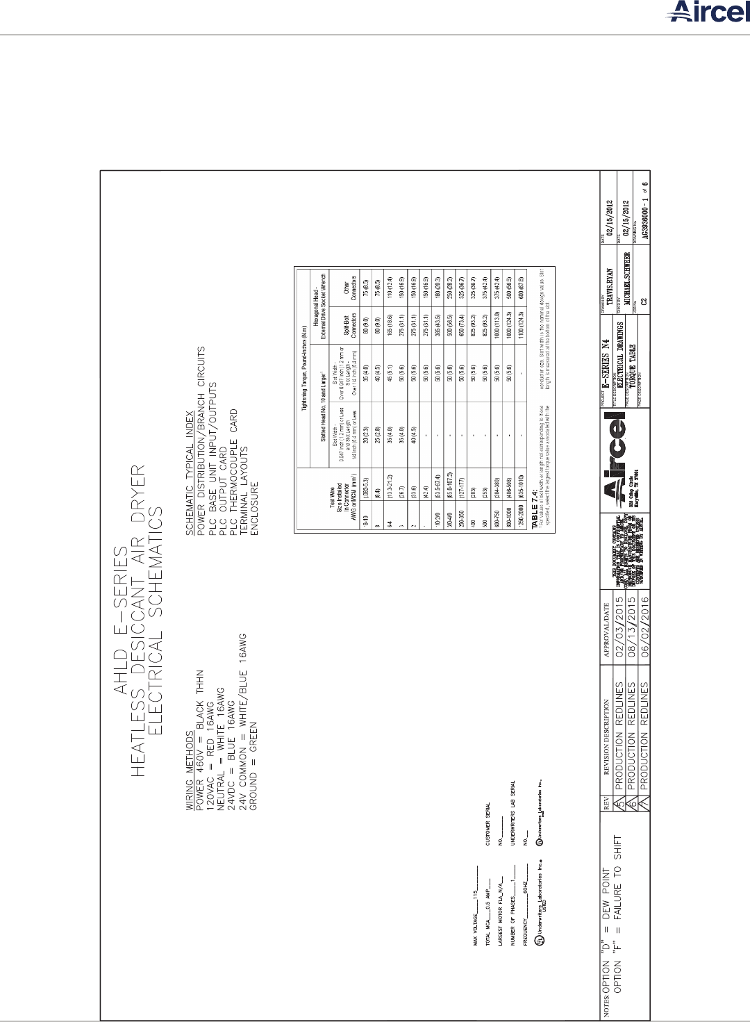
AHLD Series Manual |
Desiccant Air Dryer User Manual
39
APPENDIX C: DRAWINGS
C.1 Electrical Schematic Drawings

| AHLD Series Manual
Desiccant Air Dryer User Manual
40
C.2 Main Power & PLC Input Drawings

AHLD Series Manual |
Desiccant Air Dryer User Manual
41
C.3 PLC Outlet & Sensor Drawings

| AHLD Series Manual
Desiccant Air Dryer User Manual
42
ITEMNUMBER PARTNUMBER DESCRIPTION QTY
1 AG3197201 BACKPLATEFITS14x12 1
2 AG3948924 POWERSUPPLY,24VDC 1
3 AG3934769 POWERSUPPLY,5VDC 1
4 AG3251901 ANCHOR,SCREWEND,G RAY 6
6 AG3253101 TERMINALBLOCK,GRAY,J4 2
7 AG3253001 TERM INAL BLK,GREEN/YELLOW,J4 1
8 AG3933672 TERMINALBLOCK,BLUE,J3 4
9 AG3933345 TERMINALBLK,GRAY,J 3 30
10 AG3948856 RELAY,SCREWTYPETERMINAL,SPDT 1
11 AG3182201 DUCT,WHITE,NARROWSLOT,1"X2" 3
12 AG3480590 COVER,WHITEDUCT,1" 3
13 AG3933346 TERMINALBLK, GREEN/Y ELLOW,J3 3
14 AG3948855 RELAY,SCREWTYPETERMINAL,DPDT 3
C.4 Back Panel Drawings

AHLD Series Manual |
Desiccant Air Dryer User Manual
43
ITEMNUMBER QTY P ARTNUMBER DESCRIPTION
50 1 AG3934778 EZDDISPLAY
51 1 AG3934775 EZDPROCESSOR
52 1 AG3934777 EZDI/OMODULE
54 1 AG3935996 ENCLOSURE,MODIFIED,14x12
55 1 AG3935091 SWITCH,PUSHBUTTON,ROUND
56 1 AG3935094 CONTACTBLOCKFORPUSHBUTTON
58 4 AG3935998 LIGHT,BLUE,6MM
59 2 AG3288701 MYERSHU BS
60 2 AG3342801 1/2XCLO SECONDUITNIPPLES
62 2 AG3101501 VALVE,SOLENOID,3WAY,NEMA4
C.5 Enclosure Layout Drawings

| AHLD Series Manual
Desiccant Air Dryer User Manual
44
AHLDE‐SERIESELECTRICALDRAWING,AIRCEL
PROGRAMMABLE
CONTROLLER,NEMA‐4WITHENERGY
MANAGEMENT.
StockNumber StockDescription Quantity Spare?
AG3934778 EZDCONTROLLER,PROCESSOR 1 Y
AG3934775 EZDCONTROLLER,12DCINP UTS 1 Y
AG3934777 EZDCONTROLLER,CPU 1 Y
AG3935996 ENCLOSURE,MODIFIED,14X12 1 N
AG3935091 SWI TCH,PUSHBUTTON,ROUND 1 Y
AG3935094 SWITCH,CONTACTBLOCK,FORALL 1 Y
AG3935095 LIGHT,FOR800BSWITCH,LED 1 Y
AG3935096 LENSFORPUSHBUTTON,GREEN 1 Y
AG3935998 LIGHT,PILOT,115V,8MM,BLUE 4 Y
AG3288701 HUB,MYERS,1/2" 2 Y
AG3342801 NIPPLE,CONDUIT,1/2"XCLOSE, 2 N
AG3481168 STRAI NRELIEF,3/8" 3 N
AG3481158 LOCKNUT,3/8" 3 N
AG3481159 RINGSEAL,3/8" 3 N
AG3948855 RELA Y,SCREWTYPETERMIN AL,DPDT 3 Y
AG3197201 PANEL,BACKPLATE,FITS14x12 1 N
AG3948924 POWERSUPPLY,24VDC 1 Y
AG3934769 POWERSUPPLY,5VDC 1 Y
AG3251901 ANCHOR,SCREWEND,GRAY 6 N
AG3253101 TERMINALBLOCK,GRAY,J4 2 N
AG3253001 TERMINALBLOCK,GREEN/YELLOW,J4 1 N
AG3933672 TERMINALBLOCK,BLU,J3 4 N
AG3933345 TERMINALBLOCK,GRAY,J3 30 N
AG3948856 RELAY,SCREWTYPETERMINAL,SPDT 1 Y
AG3182201 DUCT ,WHITE,NARROWSLOT,1x2 3 N
AG3101501 VA LVE,SOLENOID,3WAY,NEMA4,1/4" 2 Y
AG3933346 TERM INALBLK,GREEN/YELLOW,J3 3 N
AG3480590 COVER,WHITEDUCT,1" 3 N
AG3481460 CORD,SJEEO W,18/3 10 N
AG3480463 WIRE#18,BL UE 80 N
AG3480947 WIR E#18,RED 98 N
AG3480948 WIRE#18,WHITE 17 N
AG3480991 WIRE #18,WHITE/BLUE 9.5 N
AG3373901 WIRE#16,ORANGE 6 N
AG3372301 WIRE#16,GREEN 12 N
C.6 Electrial Part Drawings

AHLD Series Manual |
Desiccant Air Dryer User Manual
45
DATE SERVICE PERFORMED NOTES
NOTES

| AHLD Series Manual
Desiccant Air Dryer User Manual
46
DATE SERVICE PERFORMED NOTES
NOTES

AHLD Series Manual |
Desiccant Air Dryer User Manual
47
DATE SERVICE PERFORMED NOTES
NOTES
| AHLD Series Manual
Desiccant Air Dryer User Manual
48
DATE SERVICE PERFORMED NOTES
NOTES

AHLD Series Manual |
Desiccant Air Dryer User Manual
49
DATE SERVICE PERFORMED NOTES
NOTES

| AHLD Series Manual
Desiccant Air Dryer User Manual
50
DATE SERVICE PERFORMED NOTES
NOTES

AHLD Series Manual |
Desiccant Air Dryer User Manual
51
WARRANTY INFORMATION
Aircel warrants that its Standard Refrigerated Air Dryers are
free from defects in materials and workmanship for two
years from the date of invoice. Warranty coverage for this
time period will be parts and labor for the rst year and parts
only for the second. Custom engineered products, desiccant
dryers, chillers and nitrogen generators are warranted to be
free from defects in materials and workmanship for one year
from date of invoice. Warranty coverage for this time period
will be for parts and labor.
Aircel warranty excludes damages due to corrosion, lack of
proper maintenance, incorrect installation, modication,
or misapplication of equipment. Routine maintenance or
adjustment required under normal operation as outlined
in the Aircel operation and maintenance manuals are not
covered under warranty.
Once Aircel has been given adequate opportunity to remedy
any defects in material or workmanship in accordance with
Aircel Warranty Policy and Procedures, Aircel retains the sole
option to accept return of the goods, with freight paid by the
purchaser, and to refund the purchase price for the goods
after conrming the goods are returned undamaged and in
usable condition. Such a refund will be the full extent of Aircel
liability. Aircel shall not be liable for any other costs, expenses
or damages whether direct, indirect, special, incidental,
consequential or otherwise. The terms of this warranty may
be modied only by a special warranty document signed by a
CEO, General Manager or Vice President of Aircel.
There exist no other representations, warranties or guarantees
except as stated in this paragraph and all other warranties,
including merchantability and tness for a particular purpose
whether express or implied, are hereby expressly excluded
and disclaimed.

Parts & Service
For genuine Aircel replacement parts, call
800.767.4599
For faster service, please have your unit model
and serial number, part number, or description.
Aircel LLC | 323 Crisp Circle | Maryville, TN 37801 | 865.767.4599 | airceldryers.com
