
AEHD Series | Externally Heated | 150 - 3,000 scfm
DESICCANT DRYER USER MANUAL
The information in this manual is current as of its publication date and applies to AEHD Series desiccant air dryers until next revision of this manual.
Copyright © 2017 Aircel, LLC. All rights reserved.
WARRANTY NOTICE
Failure to follow the instructions
and procedures in this manual, or
misuse of this equipment, will void its
warranty.
WARNING!
Users are required to read the entire
User Manual before handling or using
the product. Keep the User Manual in
a safe place for future reference.

| AEHD Series Manual
Desiccant Air Dryer User Manual
ii
DRYER DATA SHEET
Model Number: Serial Number:
Date of Manufacture:
Ship Date: Installation Date:
Customer Address:
Customer City: State/Zip:
Other:

AEHD Series Manual |
Desiccant Air Dryer User Manual
iii
TABLE OF CONTENTS
Section 1: Safety 1
1.1 Introduction 1
1.2 Safety Signal Words 1
1.3 General Safety Procedures 1
1.4 Safe Operating Procedures 2
1.5 Desiccant Safety Precautions 2
1.5.1 Desiccant First Aid Recommendations 2
1.6 Implementation of lockout/tag-out 2
1.6.1 Procedures 3
1.6.2 General Security 3
Section 2: Description 4
2.1 Introduction 4
2.2 System 4
2.2.1 How It Works 4
Section 3: Installation 6
3.1 Inspection on Arrival 6
3.2 Lifting Information 6
3.3 Installation Codes and Procedures 7
3.4 Locating and Installing the Dryer 7
3.5 Preliminary Start-Up Checklist 9
Section 4: Operation 12
4.1 Operating Procedures 12
4.2 Short-Term Shut Down 12
4.3 Short-Term or Long-Term Shut Down 12
Section 5: Controllers 14
5.1 Main Screens 14
5.2 Dryer Operation Screens 16
5.3 Alarm Screen 20
Section 6: Maintenance 22
6.1 Introduction 22
6.2 Maintenance 22
6.2.1 Weekly 22
6.2.2 Semi-Annual 22
6.2.3 Annual 23
Section 7: Troubleshooting 24
7.1 Introduction 24
7.2 AEHD Series Troubleshooting Guide 25
Appendix A: Specifications 26
A.1 Table of Specifications - AEHD Series 36
Appendix B: Material Safety Data Sheets 27
B.1 Activated Alumina Desiccant 27
Service Notes 34
Warranty Information 39


AEHD Series Manual |
Desiccant Air Dryer User Manual
1
1.1 Introduction
To ensure maximum performance and safe operation of
an Aircel desiccant dryer covered by this manual, everyone
involved with the dryer’s installation, operation, and
maintenance must read and carefully follow the instructions
in this manual.
Misuse or modification of this equipment may result in
personal injury. Do not misuse or modify. The high efficiency
heated regenerative desiccant dryer is used exclusively for
purifying compressed air in non-hazardous locations.
The state-of-the-art system is designed and constructed
in accordance with the rules and regulations regarding
adsorption technology and industrial safety. There are
hazards accompanying this type of product if not operated
for the intended purpose by trained and specialized
personnel.
1.2 Safety Signal Words
Throughout this manual, signal words are present to advise
of safety precautions and/or standard practices. Obey these
signal words as dened below:
DANGER! - Indicates an imminently hazardous situation
which, if not avoided, will result in death or serious injury.
WARNING! - Indicates a potentially hazardous situation
which, if not avoided, could result in death or serious injury.
CAUTION! - Indicates a potentially hazardous situation
which, if not avoided, may result in minor or moderate
injury.
NOTICE - used to address practices not related to personal
injury.
1.3 General Safety Procedures
• Electrical work must conform to the specifications
indicated by Aircel and any local or state laws that may
apply. In the absence of such codes, install unit according
to National Electrical Code, NFPA No. 70 latest edition.
• Personnel must wear appropriate safety gear including
eye and ear protection before working on any electrical
or mechanical aspects of the machine.
• Appropriate tools have to be used for all installation and
maintenance work. If special tools are not available to
the installation crew, contact the factory or your Aircel
representative.
• A copy of the Operation Manual must be made available
to all personnel involved with the installation, operation,
and maintenance of the equipment.
• Before performing any maintenance operations on
the equipment, the unit must be shut down, isolated,
electrical power removed, and completely depressurized.
• To ensure compatibility and continued trouble free
operation, only genuine Aircel parts must be used.
• DO NOT make any constructional changes to the unit.
Only Aircel or its authorized representatives with the
prior approval can perform any constructional work on
the machine.
• DO NOT use foreign parts.
• DO NOT use compressed air from the dryers for
breathing purposes - install a breathing air package to
ensure conformance with OSHA regulations.
• DO NOT disable or disengage any protective equipment
used on the machine.
NOTICE
For optimum performance, use only Aircel replacement
parts.
SECTION 1: SAFETY
CAUTION!
Misuse / modication hazard
Misuse or modication of this equipment may result
in personal injury.
Do not misuse or modify this equipment under any
conditions.

| AEHD Series Manual
Desiccant Air Dryer User Manual
2
1.4 Safe Operating Procedures
• Pressurize and depressurize compressed air SLOWLY!
Always open air valves slowly when pressurizing the airline
system or equipment. Repair air slowly when depressurizing
your air system or equipment.
• Circuit breakers, fusable disconnect, and wiring should
conform to national and/or local electrical codes. Make
certain that qualified electrical personnel perform the
electrical installation for this unit.
• Only use original fuses for the rated voltage and current.
• Shut down the unit in the correct recommended procedure.
• Before any work on system, always depressurize the unit
and remove all electrical power.
• After shut down, put up warning notice to prevent the unit
from being switched “ON” accidentally.
• Inspect all piping, hoses, and connections. Make sure that
all hoses are in good condition and are rated for the correct
working pressure. Do not allow hoses to come into contact
with oils, chemicals, or sharp objects.
• Secure condensate drain lines. Unsecured, flexible drain
lines may whip violently under pressure and may cause
bodily harm.
1.5 Desiccant Safety Precautions
1.5.1 DESICCANT FIRST AID RECOMMENDATIONS
1.5.1.1 INHALATION
Use a contoured dust mask during loading and unloading
operations. If high concentrations are inhaled, immediately
move to fresh air. Keep person calm. If not breathing, give
articial respiration. If breathing is dicult, give oxygen. Call a
physician.
1.5.1.2 SKIN CONTACT
In case of contact, immediately flush skin with plenty of soap
and water for at least 15 minutes.
1.5.1.3 EYE CONTACT
In case of contact, immediately flush eyes with plenty of water
for at least 15 minutes. Call a physician.
1.5.1.4 SPILLS
Clean accidental spills by vacuuming, sweeping, or flushing to a
sewer treated for suspended solids. Avoid creating excess dust.
1.6 Implementation of lockout/tag-out
The energy control procedure denes actions necessary to
lockout a power source of any machine to be repaired, serviced,
or set-up, where unexpected motion, or an electrical or other
energy source, would cause personal injury or equipment
damage. The power source on any machine shall be locked
NOTICE
These dryers do not supply breathing quality air
Aircel AEHD Series dryers do not remove carbon
monoxide and is not safe for human respiration
(breathing). Breathing air must be at least grade
D quality as described in compressed air and gas
association (CAGI) commodity specications 67.1-1966.
User may refer to OSHA 29 CFI 1910.134 for special
precautions and equipment suitable for breathing air
applications. Aircel disclaims any liability what so ever
for loss, injury or damage.
WARNING!
Inhalation, Skin, & Eye Irritant
The desiccant used in this equipment is not considered
hazardous. Contact with and disposal of desiccant
must be in accordance with the relevant MSDS and
all local codes and regulations. The following lists the
more common safety measures to be observed during
loading and unloading operations. Reference the
MSDS in the appendix for complete safety measures.

AEHD Series Manual |
Desiccant Air Dryer User Manual
3
out by each employee doing the work except when motion is
necessary during setup, adjustment, or troubleshooting.
1.6.1 PROCEDURES
The established procedures for the application of energy
control shall cover the following elements and actions and
shall be initiated only be Authorized Persons and done in the
following sequence:
1. Review the equipment or machine to be locked and tagged
out.
2. Alert operator and supervisor of which machine is to be
worked on, and that power and utilities will be turned o.
3. Check to make certain no one is operating the machine
before turning power o.
4. Turn o the equipment using normal shut-down procedure.
5. Disconnect the energy sources:
a. Air and hydraulic lines should be bled, drained, and
cleaned out. There should be no pressure in these lines
or in the reservoir tanks. Lockout or tag lines or valves.
b. Any mechanism under tension or pressure, such as
springs, should be released and locked out or tagged.
c. Block any load or machine part prior to working under it.
d. Electrical circuits should be checked with calibrated
electrical testing equipment and stored energy and
electrical capacitors should be safely discharged.
6. Lockout and/or tag out each energy source using the
proper energy isolating devices and tags. Place lockout
hasp and padlock or tag at the point of power disconnect
where lockout is required by each person performing work.
Each person shall be provided with their own padlock and
have possession of the only key. If more than one person is
working on a machine, each person shall ax personal lock
and tag using a multi-lock device.
7. Tag-lock devices shall be used only when power sources
are not capable of being locked out by use of padlocks and
lockout hasp devices. The name of the person axing the
tag to power source must be on tag along with date tag was
placed on power source.
8. Release stored energy and bring the equipment to a “zero
mechanical state.”
9. Verify isolation: Before work is started, test equipment to
ensure power is disconnected.
1.6.2 GENERAL SECURITY
1. The lock shall be removed by the Authorized Person who
put the lock on the energy-isolating device. No one other
than the person/persons placing padlocks and lock out
hasps on power shall remove padlock and lockout hasps
and restore power. However, when the authorized person
who applied the lock is unavailable to remove it, her or his
Supervisor may remove padlock(s) and lock out hasp(s) and
restore power only if it is rst:
a. veried that no person will be exposed to danger..
b. veried that the Authorized Person who applied the
device is not in the facility.
c. noted that all reasonable eorts to contact the Authorized
Person have been made to inform her or him that the
lock out or tag out device has been removed.
d. ensured that the Authorized Person is notied of lock
removal before returning to work.
2. Tag out system - Tags are warning devices axed at points
of power disconnect and are not to be removed by anyone
other than the person placing tag on power lockout. Tags
shall never be by-passed, ignored, or otherwise defeated.

| AEHD Series Manual
Desiccant Air Dryer User Manual
4
2.1 Introduction
Aircel AEHD Series dryers are engineered and manufactured
to provide you with many years of trouble free service. To
ensure that you get the get first class service from this
equipment, we recommend you take some time and read
the contents of this manual.
This manual contains information required for installing
and maintaining your new equipment. It also includes the
safety procedures and corresponding drawings. We strongly
suggest that all personnel involved with the machine, read
the entire contents of the manual before proceeding with
the installation or maintenance activities.
The manufacturer reserves the right to make changes
without any prior notification and is not obligated in any
manner. Information in this manual is deemed current at
the time of publication and Aircel disclaims all liability for
any errors resulting in any loss or damage.
2.2 System
The AEHD Series externally heated desiccant air dryer
products cover the flow range listed on the manual front
cover and provides reliable dew point performance. The
heated regenerative desiccant dryer is a continuous-duty
compressed air dryer used in industrial applications to
provide high drying efficiency for large volume airflows.
Continuous duty means no downtime. A switching valve
alternates the desiccant chambers between the drying and
regeneration phases. While one chamber is drying, the
other is regenerating.
The self-contained heated regenerative desiccant dryer
includes a control system, dryer, heater, and silencers.
Untreated compressed air contains many contaminants
such as water, compressor oil, pipe scale and contamination
from ambient air. These contaminants cause excessive
corrosion, erosion, freezing and product contamination to
all components that come in contact with the untreated
compressed air.
A regenerative type dryer system with all recommended
filtration will remove these contaminants to harmless
levels. The end result is that instruments that come in
contact with the dry compressedair stay clean and do not
corrode, therefore lasting much longer. Products that may
come in contact with clean dry compressed air are virtually
unaffected, hence rejection rates are reduced.
Aircel AEHD series externally-heated regenerative desiccant
compressed air dryers dry compressed air to -40°F PDP
(Pressure Dew Point). The compressed air stream is passed
through a desiccant bed, which removes the moisture
through the process of adsorption. Twin towers filled with
activated alumina desiccant alternate between drying and
regeneration. These dryers offer fail-safe design in the
event of power interruption, as air will continue to flow
through the dryer without dead heading and purge exhaust
valves will close, preventing loss of air pressure.
An LCD display provides operation information and tower
operating status. The highest quality non-lubricated air/gas
valves are used to ensure reliable operation for many years
to come.
2.2.1 HOW IT WORKS
The Aircel model AEHD is an externally-heat reactivated
desiccant compressed air dryer system, with two vessels
each loaded with activated alumina desiccant to adsorb
moisture from the inlet moisture-laden air stream.
While one vessel is drying (removing) moisture vapor from
the inlet air, the other vessel is regenerating (desorbing)
moisture from desiccant media that was adsorbed onto
the desiccant surfaces during the drying cycle to enable the
regenerated desiccant to dry the inlet air again.
During the regeneration process, a small portion of dry
outlet air is heated to a temperature of 400°F to regenerate
(remove) the moisture from the desiccant bed.
The drying and regenerating process is repeated
continuously between the two towers every 4 hours to
provide an uninterrupted continuous clean, dry airflow to
the customer process.
The inlet moisture-laden, dirty, compressed air is filtered
as it passes through the standard high-efficiency inlet
coalescing pre-filter where moisture and possible oil-mist
are coalesced into larger droplets. These droplets are then
removed via an automatic drain before the filtered air
enters the dryer.
NOTE: The dryer is designed to remove moisture in vapor
form only - liquid moisture and oil is detrimental to the
dryer system.
The inlet moisture-vapor laden compressed air continues to
the inlet valve and is directed to the bottom of the on-line,
pressurized drying desiccant vessel. The air stream is dried
by the vessel desiccant media and exits the top of the vessel
to the outlet valves (typically check valves), then directed to
the standard outlet high temperature particulate after filter
to remove particulates from the dry outlet air stream before
entering the downstream customer process.
The standard EMS (Energy Management System) control
system continually monitors the mid-bed humidity level
SECTION 2: DESCRIPTION

AEHD Series Manual |
Desiccant Air Dryer User Manual
5
Pre-Filter
Tower 1 Tower 2
Heater
After Filter
FIGURE 2-1: TYPICAL SCHEMATIC FLOW DIAGRAM
AEHD Series 150 - 3,000 scfm rated model
in the on-line drying vessel. At the end of the drying cycle, if
the moisture level is below the set level, the drying cycle will
continue on the same vessel for an extended time until the
moisture level reaches the set point. The EMS control system
saves energy by extending the drying cycle, thus reducing the
overall average process air consumption used for regeneration,
as well as reducing overall heater on-time in periods of low load
demand.
While one vessel is drying the inlet moisture-laden compressed
air, the other vessel is regenerating the desiccant bed.
During the regenerating cycle, the regenerating vessel is first
depressurized slowly to atmospheric pressure through a purge
exhaust valve and muffler to ambient. A small portion of the
outlet dried compressed air flows through a purge adjustment
valve to an orifice to reduce the regenerating airflow.
The regeneration purge air flows to the heater at near
atmospheric pressure where the regeneration air temperature
is heated to a temperature of 400°F. The air then passes
through the regeneration heater check valve on the upper
line and into the regenerating vessel where the moisture is
desorbed (removed) from the vessel desiccant bed.
The hot, moist regeneration air then flows from the bottom of
the vessel to the purge exhaust valve and muffler to ambient.
Dryer system operation is performed automatically by the APC
(Aircel Programmable Controller) control system. The standard
drying and regeneration time cycle is an 8 hour NEMA cycle.
While one vessel is drying incoming compressed air for 4 hours,
the other vessel is (1) depressurizing for 2 minutes, (2) heat
regenerating/purging for 3 hours, (3) cooling/regenerating/
purging for 55 minutes, (4) repressurizing the vessel to the line
pressure for 3 minutes before (5) switching over to the other
vessel, any finally, (6) just before the end of the repressurization
period the EMS system checks the moisture level in the drying
vessel.
If the EMS senses moisture levels are below the set point,
the drying vessel will remain online, drying for an extended
time and the regenerated vessel will be in standby and
repressurized. When the drying vessel reaches the set moisture
level, the vessels will switch. Switching from one vessel to the
other vessel is performed only when both desiccant towers are
at line pressure to prevent line surge and to minimize desiccant
abrasion.
The dryer system process is fully automatic and continuous,
typically switching vessels every 4 hours, alternating between
drying and regenerating.
NOTE: The EMS (Energy Management System) control system
will extend drying mode for longer than the 4 hour period.

| AEHD Series Manual
Desiccant Air Dryer User Manual
6
3.1 Inspection on Arrival
All heated regenerative desiccant dryers are tested and
operated before shipment. However, shipping vibration may
cause damage such as loosening of certain parts. To ensure
smooth installation, it is recommended that immediately upon
receipt of the unit, the system is checked for the following:
1. Inspect unity on delivery.
2. Report any damage to the delivery carrier.
3. Request a written inspection report from the Claims
Inspector to substantiate the claim.
4. File claims with the delivery carrier.
5. Compare unit received with description of product ordered.
Check the serial plate label and make sure that it is the
correct Model was ordered. Note the equipment Capacity
and Power Supply requirements and ensure that they are in
accordance with your specifications. The rated conditions
of the dryer are indicated on the serial plate label. If there
is any discrepancy, contact your representative listed on
the manual back cover.
6. Vibration during shipping can loosen the connections.
Inspect all pipe and tubing and make sure they are all
tightened and secured.
7. Report incomplete shipments to the delivery carrier and
your service representative.
3.2 Lifting Information
1. Use all lifting points provided. Special care must be used
when lifting the dryer to prevent tip-over.
2. Use clevis connectors, not hooks, on lifting slings.
3. Only lift unit under support frame/base by using the fork
lift openings provided. Do not lift by piping.
4. Check the approximate weight provided on the specification
control drawing to ensure adequate lift truck capacity.
5. Allow only qualified operators to lift the equipment.
6. Refer to applicable OSHA regulations and local codes when
using cranes, forklifts, and other lifting equipment.
SECTION 3: INSTALLATION
WARNING!
Lifting Hazard
Failure to lift the unit correctly can result in severe
personal injury or property damage.
• Use appropriate lifting equipment and adopt
all safety precautions needed for moving and
handling the equipment.
• A forklift, or crane is recommended for unloading
and installation.
• Lift unit by lifting lugs and frame only. Do not lift
by piping.

AEHD Series Manual |
Desiccant Air Dryer User Manual
7
3.3 Installation Codes and Procedures
• Safe and efficient operation of the unit depends on proper
installation.
• Authorities with jurisdiction should be consulted before
installing to verify local codes and installation procedures.
In the absence of such codes, install unit according to the
National Electric Code and NFPA No. 70-latest edition.
• A qualified installation and service agent versed in all
regulatory codes must complete installation of this unit.
• All shipping materials, including shipping covers, must be
removed from the unit prior to, or during, unit installation.
3.4 Locating and Installing the Dryer
1. Locate unit on a level foundation. Dryer should be mounted
on a suitably structured flat and level floor or base that is
free from vibration. Special care must be used when lifting
the dryer to prevent tip-over.
2. Bolt dryer skid to the foundation using the bolt holes
provided in the frame. The frame(s) must be securely
bolted to the foundation to prevent movement resulting
from earth tremors and induced piping vibration.
3. Make certain all shipping materials have been removed
such as crating, plastic wrap, fitting covers, etc.
4. Install unit to provide adequate clearance for maintenance
services. Dryer and accompanying filters should be installed
with at least three (3) feet clearance from the adjoining
walls to provide easy access for routine maintenance and
adequate air flow.
5. Unit should be located in a weather protected area with a
temperature range between 70 - 100°F.
7. Install flanges, fittings, and piping on system using the
correct pipe size and pressure rating.
7.1 Outlet piping and components should be rated for a
minimum of 250°F
7.2 Connect inlet piping and shutoff valve of the dryer to the
moist air from the compressor/receiver/inlet filter.
7.3 Connect outlet piping with outlet shutoff valve.
8. A block and bypass valve system can be installed around
dryer system to keep the downstream air supply pressurized
during repair or maintenance of the dryer system.
WARNING!
Electric Shock Hazard
This machine is connected to high-voltage power,
which can cause severe electrical shock and injury.
• Follow proper lock out/tag out procedures before
performing service or maintenance work.
• Electrical installation must be performed by a
qualied electrician and comply with all applicable
national and local codes.
CAUTION!
High Heat Hazard
During vessel switchover, the dryer outlet line and lter
may become extremely hot (250°F) for approximately
20 minutes.
Dew point spike may be a longer duration if airow
through the dryer is lower than the rated ow. In an
upset condition, outlet temperature could exceed
400°F.
CAUTION!
Moisture contamination hazards
Air supplied while the regenerative desiccant dryer is
bypassed will be wet and saturated. Some downstream
processes may not tolerate this air supply due to the
risk of contamination of sensitive equipment.
WARNING!
High heat hazards
Ensure the bypass valve(s) are rated for a minimum of
250°F. An upset condition could exceed 400°F.

| AEHD Series Manual
Desiccant Air Dryer User Manual
8
9. Compressed air piping must be at least the same size as
that of the inlet and outlet connections of the dryer. If
necessary, larger pipe sizes can be used with reducers.
10. Provide adequate power supply. See rating and
specification information on dryer data label and drawing
package information. Make certain dryer system is properly
grounded.
11. A back pressure regulator can be installed at the air outlet
of the dryer to keep the dryer at a constant pressure
regardless of downstream demand. This prevents the
dryer media bed from fluidizing (lifting/moving) due to a
high downstream demand and high pressure loss in the
dryer system. This fluidization causes high velocity in the
media bed and leads to fluidization of the media, affecting
dryer performance and reducing the life of the desiccant
bed media.
12. The dryer relief valves are designed and sized to relieve
excess pressure resulting from the thermal expansion
of air trapped in the vessels in the event the vessels are
subjected to heat, such as in a conflagration. Valves are set
to relieve at the maximum design pressure of the desiccant
vessels.
13. In the event that mufflers have been shipped loose, install
and secure to the back of the desiccant towers.
14. Ensure the dryer towers are filled with desiccant. Larger
dryers may have desiccant shipped separately; in which
case, the media has to be filled into the pressure vessels
from the desiccant fill ports at top of each vessel. Care
must be taken when filling the media and must be done
gradually to prevent powdering.
15. Install the Aircel inlet compressed air particulate pre-
filter drain to an open drain system for safety and to
prevent puddling of water at dryer system area. Piping
should be secured and angled slightly downward to drain
condensate. Drain system must have a vented air gap to
prevent a pressurized condition.
16. If you intend to vent your exhaust with additional piping,
the discharge piping from the exhaust should not be piped
upward without an arrangement for removing trapped
condensate. Make sure that you do not apply a back
pressure on this exhaust system. If exhaust piping is to be
extended, stay within 15 to 20 feet and use larger diameter
piping.
17. The automatic drain can be piped to an open drain system
if allowed, or to a condensate treatment system, then to
an open drain system. Make sure the piping is secured and
rated for the pressure and temperature of the application,
WARNING!
Unsafe personnel conditions hazard
Keep personnel safely away from desiccant dryer relief
valves. In the event of discharge, the relief valves can
cause an unwanted condition or hazard to personnel.
Some discharge ports could be piped to a safe location.
Drain
Valve
Air or Water
Cooled
Condenser
Air
Compressor
Drain
Valve
Dry Air
to Plant
Drain
Valve
Drain
Valve
After Filter
Pre-Filter
Separator
FIGURE 3-1: Typical Installation Setup

AEHD Series Manual |
Desiccant Air Dryer User Manual
9
and can be removed if filter bowl (in some systems) needs
to be removed for servicing.
18. Make all electrical connections to the system as shown on
the wiring diagram. Special care must be taken in connecting
the proper voltage as indicated on the specification sheet
and wiring schematic. It is recommended to supply power
to the dryer system through a customer supplied fused
disconnect switch to remove all power to the system.
19. If proper system pressure cannot be maintained in the
adsorption vessel during drying, install a system back
pressure valve downstream of the dryer to protect the
dryer from high velocity resulting from low service pressure.
Failure to maintain the correct operating pressure will
cause elevated dew point and premature failure of the
desiccant.
20. If there are any changes in the operating conditions of
the system from those published in this manual, contact
Technical Support at the number published on the back of
this manual.
3.5 Preliminary Start-Up Checklist
In addition to the below notes, cautions and warnings, refer
to the previous sections on General Safety Procedures, Safe
Operating Procedures and any safety procedures required by
end user.
1. Check the inlet and outlet connections are the correct size,
pressure rating, and tightened securely.
2. Ensure the wet inlet air line is connected to the inlet pre-
CAUTION!
Follow local codes
Before connecting condensate to open drainage
system make certain this is allowed, user or local
codes may require treatment before discharging into
drain system.
WARNING!
Electric Shock Hazard
This machine is connected to high-voltage power,
which can cause severe electrical shock and injury.
• Follow proper lock out/tag out procedures before
performing service or maintenance work.
• Electrical installation must be performed by a
qualied electrician and comply with all applicable
national and local codes.
Aircel LLC is not liable for any code violations,
component damage, downtime or consequential
damage related to customer supplied electrical
components and connections.
WARNING!
• Tower/vessel relief valves are set from
manufacturer. DO NOT adjust these valves.
• Always pressurize and depressurize the system
slowly.
• This system must be operated or serviced by
qualied persons familiar with pressurized
systems and electrical controls.
• Before servicing any component make certain the
system is depressurized and de-energized.
• Hearing protection is recommended for personnel
protection when the system is in operation and/
or pressurized in order to protect from any loud
bursts of pressurized air to atmosphere. This can
occurs through the depressurization and purge
exhaust muers, vent ports, and lter drain ports.
• Eye protection safety glasses are recommended
for personnel protection when the system is in
operation and/or pressurized in order to protect
from possible ying debris expelled from the
purge exhaust muers during tower, vent, or
drain depressurization or any other possible ying
debris.
• Do not use the dryer without the inlet lter
element or outlet lter element.
• Do not use the dryer without the vessel desiccant
media in place.

| AEHD Series Manual
Desiccant Air Dryer User Manual
10
filter with automatic drain valve (typically, the inlet piping
flows from inlet pre-filter to bottom of vessels).
3. Ensure the dry outlet air is connected to the outlet after
filter with the manual drain valve which is piped from top
of vessels to outlet after filter.
4. Check that the correct power supply is connected to the
desiccant air dryer system with an adequate disconnect
switch.
5. Check that all manual valves are in correct open and
closed positions and that compressed air is available to be
supplied to the desiccant air dryer system.
a. Dryer system block and bypass valving (if applicable):
Outlet isolation block valve should be closed, inlet
isolation block should be open, and the bypass valve
should be open.
b. Inlet coalescing pre-filter automatic drain isolation valve
should be open.
c. If a manual vent/drain valve is used near the inlet
coalescing pre-filter automatic drain valve to ambient,
this valve should be closed. (This inlet pre-filter manual
drain valve is used in some systems in case of automatic
drain valve failure.)
d. Outlet particulate after filter manual drain/vent valve
should be in closed position.
e. Any filter differential pressure gauge isolation valves
should be in open position.
f. Any pressure gauge isolation valves should be in open
position.
g. Control air isolation valve, to be open position and
set to 100 psi, adjustable via the control air pressure
regulator located near the electrical enclosure.
6. With the customer-supplied compressed air to the system,
OPEN the inlet valve slowly (two to three minutes) to
gradually pressurize the system. Do not open valve too
quickly. Opening valve and suddenly pressurizing the
system can cause damage to the dryer heat exchanger and
other components. One vessel will pressurize slower than
the other; if one vessel does not pressurize, open the purge
adjustment valve to pressurize.
7. Check the complete dryer system for leaks. Use soap and
water to test all joints and fittings. If found, immediately
depressurize the system, repair all leaks, and re-test.
8. Turn the dryer system on via the power on/off switch.
9. After the dryer is on and operating, one tower will
depressurize to atmospheric pressure. The purge
adjustment valve can now be adjusted to 50-55 psig read
on the purge pressure gauge (located at back of dryer).
Increase or decrease purge pressure via purge adjustment
valve. The heater outlet temperature should reach at least
375 - 400°F after approx. 20-30 minutes; if temperature is
too low, start closing the purge adjustment valve in small
increments. If temperature is too high, open the purge
adjustment valve in small increments until temperature
is stable and the heater does not cycle on and off
continually. The heater should stay on almost continuous
during the heating mode. NOTE: Typical purge pressure
setting is 50 - 55 psig.
10. Refer to the system screenshots and descriptions for
additional information. The controls have an advancing
feature to check operation quicker if required and allows
the operator to make certain the dryer operates correctly
in each step in a shorter time period.
11. Open the outlet block valve slowly, then close the bypass
valve (if bypass valve was not initially closed.
12. When unit is in operation, the display on the enclosure
door will show the dryer status and any alarm conditions.
13. When a common shutdown alarm condition is active, the
system will display the shutdown alarm condition active in
the alarm screen area. Common shutdown alarms include
temperature alarms and incorrect pressure alarms (or
failure to switch), which stop dryer operation and require
manual reset. After alarm problem has been corrected
the system will need to be manually reset. The common
shutdown alarm red light will be on, and the common
shutdown alarm relay inside the enclosure will de-energize.
NOTE: High humidity could be displayed in the alarm
screen even though an actual shutdown alarm is active.
This occurs because of how the alarms overlap on the
display. The only alarm with automatic reset is the high
humidity alarm, which does not activate the common
shutdown alarm light and relay. A number of dry common
shutdown alarm contacts for remote indication are
available inside the enclosure. See electrical drawings for
terminal numbers.
14. Heater temperature control settings are factory set. The
typical setting is as follows:
a. Heat Control: 400°F
b. Heater Mid-Range: 850°F
c. Heater High Limit: 1,000°F
d. Purge Air High Limit: 500°F
CAUTION!
Some downstream systems may take a long time period
to pressurize. Make certain dryer pressure remains
at normal operating pressure while pressurizing
downstream system.

AEHD Series Manual |
Desiccant Air Dryer User Manual
11
15. If the system has an optional outlet dew point readout
with high humidity, the outlet dew point will be displayed
on the system display. Verify the needle valve prior to the
dew point sensor is fully open, the valve after the sensor is
slightly open with a slight amount of air at the end of the
exhaust coiled tube to ambient. These adjustments will set
up the airflow for the dew point sensor.
16. The optional dew point control setting are recommended
to be set at the following levels:
a. PDP: -50
b. Humidity Alarm: 10°F
These settings can be changed as necessary. The dew
point control adjustment should be within -20 to -70 PDP.
17. Verify the mid-bed RH sensor exhaust valve (part of the
standard Energy Management System on the AEHD series
dryers) is adjusted properly. This valve is located near
electrical enclosure. A small rectangular block of aluminum
houses the mid-bed RH sensor and has a needle valve
attached to it. The needle valve should be slightly opened
until a small amount of air is exhausted to ambient. This
will set up the flow of air for the mid-bed RH sensor to
operate the Energy Management System.
18. Dryer cycle times are as follows:
Drying: 4 hours
Depressurizing: 2 minutes
Heating: 180 minutes
Cooling: 55 minutes
Repressurizing: 3 minutes
19. Check drain valve for proper operation and discharge of
liquids (filters and separators, etc.). If automatic drain valve
has a drain isolation valve, make certain the valve is open
so condensate can be properly drained.
20. Verify the purge exhaust valves open slowly within a 5-8
second time period to depressurize the vessel at a slower
rate. Some adjustment of the flow control valve attached
to the actuator may be required; after adjustment, tighten
down the locking collar.
21. Verify complete dryer operation. Do not allow system to
operate unattended until satisfied the dryer system is
operating correctly.
22. After the initial start-up, the dryer operation is completely
automatic.

| AEHD Series Manual
Desiccant Air Dryer User Manual
12
4.1 Operating Procedures
After the initial startup, the dryer operation is completely
automatic. To understand the details of the operation, see
Figure 2-1: Typical Schematic Flow Chart on page 5.
4.2 Short-Term Shut Down
(For Maintenance)
The desiccant air dryer system can be shut down at any time.
Some systems may have a customer supplied bypass valve.
This can be slowly opened to allow air downstream.
1. Slowly close the outlet shut off valve (customer supplied).
2. Slowly close the inlet shut off valve (customer supplied).
3. Next, turn on power off/on switch to off position at the
dryer system electrical enclosure.
4. Disconnect main electrical power supply to dryer system.
5. Open vent valve located on bottom of the outlet after filter
to depressurize the system.
6. The system is now able to be serviced.
4.3 Short-Term or Long Term
Non-Usage Period Shut Down
SECTION 4: OPERATION
WARNING!
Electric Shock Hazard
This machine is connected to high-voltage power,
which can cause severe electrical shock and injury.
• Follow proper lock out/tag out procedures before
performing service or maintenance work.
• When the system is shutdown and power removed,
lock out power supply and depressurize system
before performing maintenance or service work
to avoid injury to personnel or property damage.
WARNING!
This type of dryer operates best if left on with air
supplied to the unit whenever possible.
This unit can be left pressurized after the dryer is
switched o.
WARNING!
Non-purified/moist bypass air could damage
sensitive downstream equipment components. Some
operations may not tolerate the contaminated air.
In these situations, do not utilize a bypass valve.

AEHD Series Manual |
Desiccant Air Dryer User Manual
13
For best purity, the system is best left isolated and pressurized.
Some systems may have a customer supplied bypass valve.
This can be slowly opened to allow air downstream.
1. Slowly close the outlet shut off valve (customer supplied).
2. Slowly close the inlet shut off valve (customer supplied).
3. Next, turn on power off/on switch to off position at the
dryer system electrical enclosure.
4. If an optional outlet dew point sensor is included int he
system, ensure the outlet needle valve attached to the
sample cell is closed. The needle valve is located closest
to the exhaust coil to ambient. No airflow should be felt at
end of coiled tube.
5. The system should now be isolated and pressurized.
WARNING!
This type of dryer operates best if left on with air
supplied to the unit whenever possible.
This unit can be left pressurized after the dryer is
switched o.
WARNING!
Non-purified/moist bypass air could damage
sensitive downstream equipment components. Some
operations may not tolerate the contaminated air.
In these situations, do not utilize a bypass valve.
| AEHD Series Manual
Desiccant Air Dryer User Manual
14
5.1 Main Screens
This is the screen where extended drying can be selected or
turned off. To select, press the OK button twice then press
the up or down arrow to highlight the appropriate selection.
Press OK to make the selection then press ESC back to the
main menu. The check mark will indicate which selection has
been made.
Fixed Time Cycles. With Energy Management selected, the
unit has the ability to save energy when regenerating is not
needed. In Energy Management, the deciding factors are the
dew point setting and the relative humidity setting. These
can be changed on the Settings Screen. Once both values
have been met, the unit will go into savings mode labeled
Extended Drying.
SECTION 5: CONTROLLERS
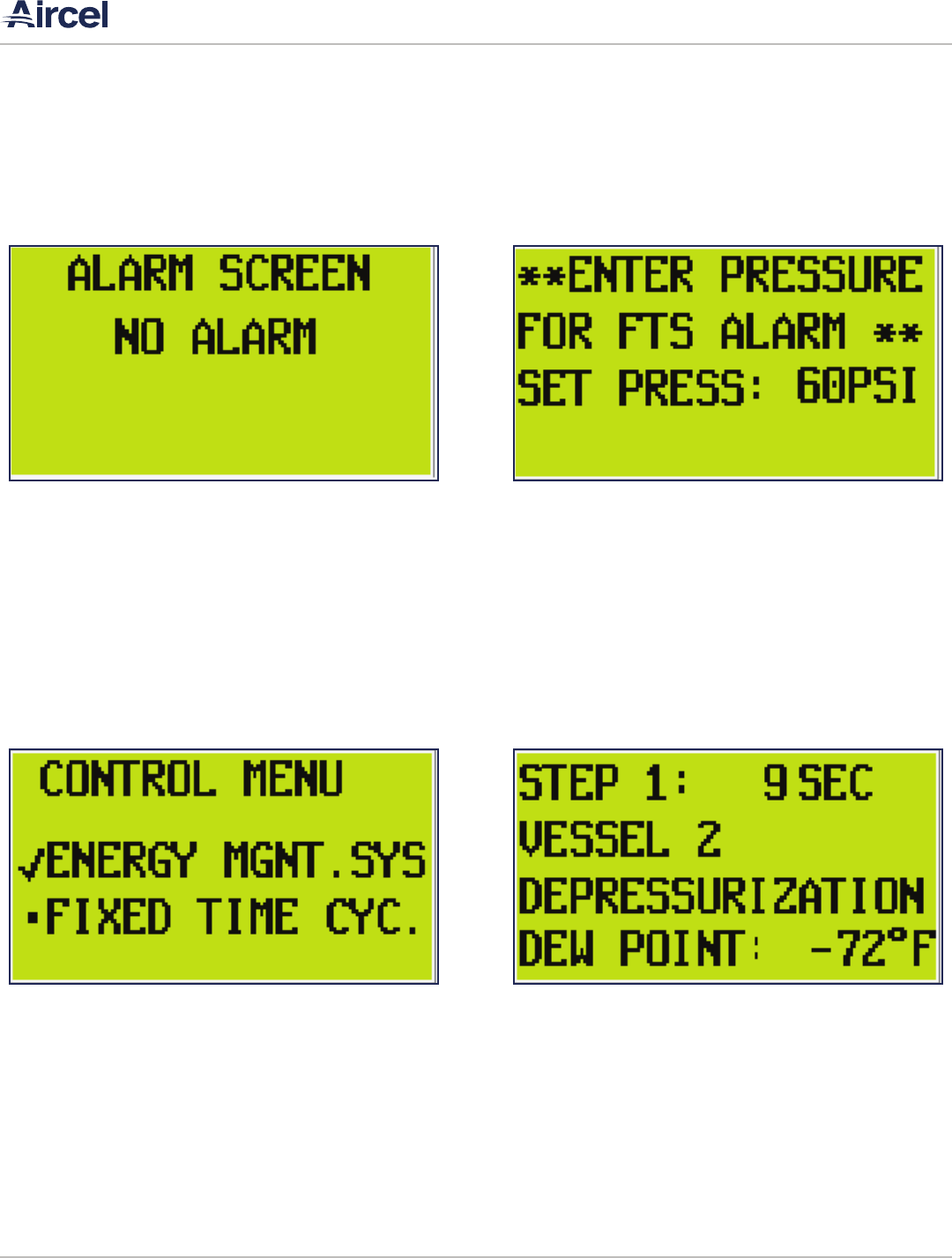
FIGURE 5-1: Alarm Screen
No alarm is when there are no active alarms. During this
state, the alarm relay contact will be active. (Normally open
contact will be closed/normally closed contact will be open).
This allows the remote alarm to trip when power is lost to
the unit.
For more detailed alarm screens, refer to section 5.3.
This screen allows the user to change the set point for the
failure to shift alarm. It is not recommended to change this
setting without first contacting the Aircel Service Department.
FIGURE 5-3: Control Menu Screen
FIGURE 5-2: Failure To Shift Entry Screen
FIGURE 5-4: Main Screen
5.1.1 Alarm Screen
5.1.3 Control Menu Screen
5.1.2 Failure to Shift Entry Screen
5.1.4 Main Screen

AEHD Series Manual |
Desiccant Air Dryer User Manual
15
The settings menu allows you to make changes to the set points
of the relative humidity, dew point and high humidity control
set points. These set points are used to control the unit for
energy savings.
The high humidity set point is to alert the user of high dew
point that could possibly lead to moisture downstream of the
dryer. To make changes to the set points, press the OK button
twice.
Next press the up or down arrows to highlight the setting to
be changed, then press the OK button again. The individual
numbers should now be flashing. Press the left or right arrows
to move to the particular number that needs to be changed
and press the up or down arrow to make the change. Once
the changes are made to the selection, press the OK button to
confirm the change.
Once all selections have been completed, press the ESC button
to return to the main menu.
The analog screen allows the user to view the sensor outputs. The total hours of operation and total hours of energy
savings can be viewed from this screen.
FIGURE 5-5: Analog Screen
FIGURE 5-7: Settings Screen FIGURE 5-8: Settings Screen
FIGURE 5-6: Operation Hours Screen
5.1.5 Analog Screen
5.1.7 Settings Screen
5.1.6 Operation Hours Screen

| AEHD Series Manual
Desiccant Air Dryer User Manual
16
5.2.2 STEP TWO: Regenerating
Step 2 is the regeneration step. In this step, vessel 2 will
be heated then cooled to help regenerate the media. The
heating/cooling step is 235 minutes (3hrs, 55mins).
To advance from heating to cooling, press and hold the up
arrow button for approx. 6 seconds then release. If not
released within another 6 seconds, the cooling step will also
be skipped. To skip the cooling mode, press the up arrow
again for up to 12 seconds.
5.2 Dryer Operation Screens
5.2.1 STEP ONE: Depressurizing
Step 1 is the depressurization step. In this step, Vessel 2
depressurizes to allow for regeneration of that tower. This
step is 120 seconds (2 minutes).
FIGURE 5-9: Step One
FIGURE 5-10: Step One
FIGURE 5-11: Step Two Heating
FIGURE 5-12: Step Two Cooling

AEHD Series Manual |
Desiccant Air Dryer User Manual
17
5.2.3 STEP THREE: Repressurizing
Vessel 2 is preparing for regeneration and Vessel 1 is drying
the inlet air.
The PLC control system energizes Solenoid SOL6, opening
purge exhaust valve K4.
Vessel 1 regeneration valve K3 and depressurization valve V1
should all be closed.
Depressurization valve V2 and Vessel 1 inlet valve K1 should
be open.
5.2.4 STEP FOUR: Extended Drying
Step 4 is the extended drying step, which is determined
by several features. Extended drying is controlled from the
controller menu screen.
On this screen, you can select either Energy Management or
Fixed Time Cycles. With Energy Management selected, the
unit has the ability to save energy when regenerating is not
needed. In Energy Management, the deciding factors are the
dew point setting and the relative humidity setting. These
can be changed on the Settings Screen. Once both values
have been met, the unit will go into savings mode labeled
Extended Drying.
FIGURE 5-13 Step Three FIGURE 5-15: Step Four
FIGURE 5-14: Step Three FIGURE 5-16: Step Four

| AEHD Series Manual
Desiccant Air Dryer User Manual
18
5.2.5 STEP FIVE: Depressurization
Step 1 is the depressurization step. In this step, Vessel 1
depressurizes to allow for regeneration of that tower. This
step is 120 seconds (2 minutes).
5.2.6 STEP SIX: Heating
Step 2 is the regeneration step. In this step, vessel 1 will
be heated then cooled to help regenerate the media. The
heating/cooling step is 235 minutes (3hrs, 55mins).
To advance from heating to cooling, press and hold the
up arrow button for approx. 6 seconds then release. If not
released within another 6 seconds, the cooling step will also
be skipped. To skip the cooling mode, press the up arrow
again for up to 12 seconds.
FIGURE 5-17: Step Five FIGURE 5-19: Step Six Heating
FIGURE 5-18: Step Five FIGURE 5-20: Step Six Cooling

AEHD Series Manual |
Desiccant Air Dryer User Manual
19
5.2.7 STEP SEVEN: Repressurization
Vessel 1 is preparing for regeneration and Vessel 2 is drying
the inlet air.
5.2.6 STEP EIGHT: Extended Drying
Step 8 is the extended drying step, which is determined
by several features. Extended drying is controlled from the
controller menu screen.
On this screen, you can select either Energy Management or
Fixed Time Cycles. With Energy Management selected, the
unit has the ability to save energy when regenerating is not
needed. In Energy Management, the deciding factors are the
dew point setting and the relative humidity setting. These
can be changed on the Settings Screen. Once both values
have been met, the unit will go into savings mode labeled
Extended Drying.
FIGURE 5-21: Step Seven FIGURE 5-23: Step Eight
FIGURE 5-22: Step Seven FIGURE 5-24: Step Eight

| AEHD Series Manual
Desiccant Air Dryer User Manual
20
5.3 Alarm Screens
5.3.1 No Alarm
No alarm is when there are no active alarms. During this
state, the alarm relay contact will be active. (Normally open
contact will be closed/normally closed contact will be open).
This allows the remote alarm to trip when power is lost to
the unit.
5.3.3 Failure to Shift
The fail to shift alarm trips if one of the vessels has not
re-pressurized, depressurized or has lost pressure during
any of the operations. Once the pressure has been restored,
the alarm will need to be manually reset to resume operation.
To do this, press the down arrow on the alarm screen.
5.3.2 High Purge Temperature
The high purge temp alarm trips when the heater outlet
temperature reaches 500°F. This causes the heater contactor
to kick out until the temperature drops down below the
alarm setting. Once the temperature comes back down, the
alarm must be reset to resume operation.
5.3.4 Heater High Limit
The heater high limit alarm trips when the heater sheath
temperature reaches 1000°F. Once the temperature falls
below the setting, the alarm will need to be manually reset
to resume operation. To do this, press the down arrow on
the alarm screen.
FIGURE 5-25: No Alarm
FIGURE 5-27: Failure to Shift
FIGURE 5-26: High Purge Temperature
FIGURE 5-28: Heater High Limit

AEHD Series Manual |
Desiccant Air Dryer User Manual
21
5.3.5 Bad RH Probe
The bad RH probe alarm trips when the Relative Humidity
sensor is out of range. This can be high (above 98%) or low
(below 1%). Once the probe has reached a number in the
range of the sensor, the alarm will automatically reset.
5.3.7 High Humidity
The high humidity alarm will trip when the dew point range is
higher than the high dew point setting on the settings screen.
Once the dew point falls below the setting, the alarm will
automatically reset.
5.3.6 Dew Point
The dew point probe alarm will trip when the sensor is out of
range. This can be high (above 67°F) or low (below -155°F).
Once the probe has reached a range that the sensor can
read, the alarm will automatically reset.
FIGURE 5-29: Bad RH Probe
FIGURE 5-31: High Humidity
FIGURE 5-30: Dew Point

| AEHD Series Manual
Desiccant Air Dryer User Manual
22
6.1 Introduction
To reach a field service technician or for technical support,
please call the number on the manual back cover.
6.2 Maintenance
Desiccant air dryers require regular maintenance for satisfactory
operation. Optimum performance can be expected if the
following routine maintenance steps are taken.
6.2.1 WEEKLY
• Check the operating conditions inlet flow, inlet temperature,
inlet pressure, and outlet dew point are in accordance with
system design parameters.
• Check all drain valves and separators.
• Check the pressure differential indicators (Delta-P) on the
pre-filter and after filter. If red or above 7 psi, replace the
filter elements. Verify the pre-filter drain is operating.
• For standard normal operation, verify the following settings:
• Control air pressure: 100 psig
• Purge air pressure: 50 - 55 psig
• EMS control setting: 7
• Verify the after-filter vent valve is closed and the inlet pre-
filter drain isolation ball valve is open.
• Verify the dew point sensor is achieving the correct dew
point and needle valves are set correctly, if applicable.
• Verify all temperature settings are correct.
• Verify no alarms are present. Refer to Section 5 for screen
shots and descriptions if necessary.
• Check mufflers. Clean or replace as needed. After first 2-3
weeks of operation, change the exhaust mufflers; after
that, replace as necessary.
• Verify EMS RH sensor needle is set correctly and exhausting
a slight amount of air to ambient.
6.2.2 SEMI-ANNUAL
• Repeat all weekly inspections and record data in the
Maintenance Log in this manual.
• Verify the system is operating properly in each sequence or
step of operation (Refer to Section 5 for more information)..
• Verify the operation of all pressure gauges, temperature
indicators, and outlet dew point sensor.
• Verify the system is free of leaks, fix any air leaks as needed.
• Remove and inspect all filters for excessive particulate
loading and physical damage. If required, replace elements
SECTION 6: MAINTENANCE
WARNING!
Electric Shock Hazard
Ensure power is disconnected from the dryer prior
to performing maintenance on the electrical or
mechanical system..
• Follow proper lock out/tag out procedures before
performing service or maintenance work.
• Prior to performing any maintenance on the dryer,
all personnel are strongly advised to familiarize
themselves with the equipment by reading the
entire contents of this operation manual.
• Follow all safety procedures prior to performing
any maintenance activity on the dryer.
CAUTION
If you notice anything unusual at any point during
the maintenance process, contact your Aircel
representative or the factory at once.
WARNING!
Refer to shutdown procedures for maintenance in
Section 3 prior to starting any maintenance on the
dryer system

AEHD Series Manual |
Desiccant Air Dryer User Manual
23
on pre-filters, after filters, and pilot air filters.
• Check desiccant condition. Powder in the mufflers is an
indication of the status of the desiccant.
• Check tightness of high and low voltage terminations.
• Check all solenoid valves - check valve seating, coil
condition, and control circuit.
6.2.3 ANNUAL
• Repeat all weekly and semi-annual inspections.
• Replace all filter elements including pre-filter, after filter,
and pilot air filter.
• Replace purge exhaust mufflers.
• Verify the operation of all pressure gauges and temperature
indicators.
• Verify system is leak-free
• Verify the system is operating properly in each sequence
or step of operation (refer to Section 5 for screen shots and
descriptions if necessary).
WARNING!
Power must be o and locked-out

| AEHD Series Manual
Desiccant Air Dryer User Manual
24
SECTION 7: TROUBLESHOOTING
7.1 Introduction
The following section briefly discusses the various faults that
can occur in the desiccant air dryer, the reason of the fault, and
how it can be rectified. If you do not find the solution to your
problem, contact your Aircel representative or the factory. All
necessary safety and precautionary steps must be followed
before attempting to perform any of the recommended
measures to resolve any faults in the air dryer.
If at any time, you notice anything unusual that can not be
resolved through this troubleshooting guide, contact your
Aircel representative or the factory at the phone number found
at the back of this manual.
Do not assume these are the only problems that may occur. All
available data concerning a problem should be systematically
analyzed before undertaking any repairs or component
replacement procedures.
WARNING!
Electric Shock Hazard
This machine is connected to high voltage power,
which can cause severe electrical shock and injury.
• Follow proper lock out/tag out procedures before
performing service or maintenance work.
• Prior to performing any maintenance on the dryer,
all personnel are strongly advised to familiarize
themselves with the equipment by reading the
entire contents of this operation manual.
• Follow all safety procedures prior to performing
any maintenance activity on the dryer.
• Some troubleshooting may have to be done while
system is pressurized and energized. Use extreme
caution.
WARNING!
Pressure Hazard
This machine contains contents under low to medium
pressure, which can cause injury.
• To avoid possible hazard or injury, the operator
should be fully familiar with the refrigerated dryer
system and its operation.
• When the system is shutdown and power removed,
lock out power supply and depressurize system
before performing maintenance or service work
to avoid injury to personnel or property damage.
CAUTION
Inappropriate Tools Hazard
Using inappropriate tools for installation or
maintenance work can lead to personal injury or
property damage.
Appropriate tools must be used for all installation and
maintenance work.
WARNING!
In addition to the below notes and warnings,
refer to general safety procedures, safe operating
procedures, and any safety procedures required by
end user.

AEHD Series Manual |
Desiccant Air Dryer User Manual
25
7.2 AEHD Series Troubleshooting Guide
Problem Probable Cause Remedy
High Dew Point
High inlet air ow • Reduce inlet air ow
Inlet air temperature above design
specication
• Reduce inlet air temperature to design specication
Poor inlet pre-ltration • Check pre-lter element(s); replace as needed
Inlet air pressure below design
specication
• Increase pressure to dryer
Purge ow shut o or not properly
adjusted
• Set purge ow to correct setting using purge adjustment valve
Back pressure in regenerating
chambers
• Muer(s) are clogged, install new muer(s). Desiccant bed
screen(s) are clogged, clean screens.
Inlet pre-lter drain not working • Clean or replace drain
Exhaust valve(s) not fully opening or
closing
• Clean and/or replace exhaust valve or actuator
Outlet check valve leaking • Clean and/or replace check valve
Purge check valve leaking • Clean and/or replace check valve
Low heater temperature or heater not
working
• Check heater temperature controller; adjust if necessary.
Check thermocouples.
Check PLC.
Check fuses.
Adjust purge adjustment valve if needed.
High Pressure
Drop
High inlet ow rate • Reduce inlet ow rate to meet dryer specication
Inlet pre-lter dirty • Inspect and replace as needed
Low inlet pressure • Increase inlet pressure to design specication
Desiccant dusting • High inlet ow velocities due to high ow

| AEHD Series Manual
Desiccant Air Dryer User Manual
26
APPENDIX A: SPECIFICATIONS
A.1 Dryer specifications - AEHD Series
For dimensions, weights, and connection sizes, see the drawing of the dryer model provided at purchase.
Type of dryer: Desiccant
Power supply: 460 VAC, 3 Ph, 60 Hz
Desiccant type: Premium grade activated alumina

AEHD Series Manual |
Desiccant Air Dryer User Manual
27
APPENDIX B: MATERIAL SAFETY DATA SHEETS
2
.
Composition/information on ingredients
CAS Number
Content (W/W)
Chemical name
1333-84-2
>= 94.0 - <= 100.0 %
Aluminum oxide (Al2O3), hydrate
3
.
Hazard identification
Emergency overview
CAUTION: MAY CAUSE EYE, SKIN AND RESPIRATORY TRACT IRRITATION
.
May cause difficulty breathing
.
Prolonged or repeated contact may result in dermatitis
.
Contact with the eyes or skin may cause mechanical irritation
.
Contains material which may indicate/cause the possibility of sensory and pulmonary irritation
.
Avoid contact with the skin, eyes and clothing
.
Avoid inhalation of dusts
.
Use with local exhaust ventilation
.
Wear a NIOSH-certified (or equivalent) particulate respirator
.
Wear safety glasses with side-shields
.
Wear chemical resistant protective gloves
.
Wear protective clothing
.
Eye wash fountains and safety showers must be easily accessible
.
Potential health effects
Primary routes of exposure
Routes of entry for solids and liquids include eye and skin contact, ingestion and inhalation
. Routes of entry for
gases include inhalation and eye contact
.
Skin contact may be a route of entry for liquified gases
.
4
.
First-aid measures
If inhaled:
Keep patient calm, remove to fresh air
.
If necessary, give oxygen
.
If not breathing, give artificial respiration
.
Seek medical attention if necessary
.
Page: 1/5
(30286124/MDS_GEN_US/EN)
Company
BASF CORPORATION
100 Campus Drive
Florham Park, NJ 07932, USA
Safety data sheet
F200
Revision date : 2009/12/04
Version: 3.0
1
.
Substance/preparation and company identification
24 Hour Emergency Response Information
CHEMTREC: 1-800-424-9300
BASF HOTLINE: 1-800-832-HELP
B.1 Activated Alumina Desiccant

| AEHD Series Manual
Desiccant Air Dryer User Manual
28
C.1 Activated Alumina Desiccant
6
.
Accidental release measures
Cleanup:
Vacuum up spilled product
.
Place into suitable container for disposal
.
7
.
Handling and storage
Handling
General advice:
Avoid dust formation in confined areas
.
Avoid contact with the skin, eyes and clothing
.
Ensure adequate
ventilation
.
Storage
General advice:
Keep container tightly closed in a cool, well-ventilated place
.
Storage stability:
Keep container dry.
8
.
Exposure controls and personal protection
Components with workplace control parameters
Aluminum oxide (Al2O3),
OSHA
PEL 5 mg/m3 Respirable fraction ; PEL 15 mg/m3 Total
hydrate
dust ;
ACGIH
TWA value 1 mg/m3 Respirable fraction ;
Safety data sheet
F200
Revision date : 2008/12/04
Version: 3.0
Page: 2/5
(30286124/MDS_GEN_US/EN)
If on skin:
After contact with skin, wash immediately with plenty of water and soap
.
Consult a doctor if skin irritation
persists
.
If in eyes:
In case of contact with the eyes, rinse immediately for at least 15 minutes with plenty of water
.
Immediate
medical attention required
.
If swallowed:
No hazards anticipated
.
If large quantities are ingested, seek medical advice.
5
.
Fire-fighting measures
Flash point:
Additional information:
Use extinguishing measures to suit surroundings
.
Hazards during fire-fighting:
No particular hazards known
.
Non-flammable.
Protective equipment for fire-fighting:
Wear self-contained breathing apparatus and chemical-protective clothing
.
NFPA Hazard codes:
Health : 0 Fire: 0
Reactivity: 1
Special:

AEHD Series Manual |
Desiccant Air Dryer User Manual
29
C.1 Activated Alumina Desiccant
Advice on system design:
Provide local exhaust ventilation to control dust
.
Provide local exhaust ventilation to maintain recommended
P.E.L
.
Personal protective equipment
Respiratory protection:
Wear a NIOSH-certified (or equivalent) particulate respirator
.
Observe OSHA regulations for respirator use (29
CFR 1910.134)
.
Wear appropriate certified respirator when exposure limits may be exceeded
.
Hand protection:
Wear chemical resistant protective gloves., Consult with glove manufacturer for testing data
.
Eye protection:
Safety glasses with side-shields
.
Body protection:
Body protection must be chosen based on level of activity and exposure
.
9
.
Physical and chemical properties
Safety data sheet
F200
Revision date : 2008/12/04
Version: 3.0
Page: 3/5
(30286124/MDS_GEN_US/EN)
Form:
Odour:
Colour:
pH value:
Melting point:
Boiling point:
Vapour pressure:
Density:
Bulk density:
Partitioning coefficient
n-octanol/water (log Pow):
Viscosity, dynamic:
Solubility in water:
10
.
Stability and reactivity
powder, granules, pellets, balls
odourless
off-white
9.4 - 10.1
2,050 °C
No data available
.
No data available
.
No data available
.
approx
.
650 kg/m3
38.0 - 52 lb/ft3
( 68 °F)
No data available
.
No data available
.
insoluble
Substances to avoid:
water
Hazardous reactions:
The product is chemically stable
.
Addition of water leads to increase in temperature
.
11
.
Toxicological information
Oral:
Information on: Aluminum oxide
LD50/rat: > 5,000 mg/kg (OECD Guideline 401)
----------------------------------

| AEHD Series Manual
Desiccant Air Dryer User Manual
30
C.1 R-134a Refrigerant
June 10, 2015 (rev. 1)
SAFETY DATA SHEET R-134a
4
7. HANDLING AND STORAGE
NORMAL HANDLING: Always wear recommended personal protective equipment.
Avoid breathing vapors and liquid contact with eyes, skin or clothing. Do not puncture or drop cylinders, expose
them to open flame or excessive heat. Use authorized cylinders only. Follow standard safety precautions for
handling and use of compressed gas cylinders. R-134A should not be mixed with air above atmospheric pressure
for leak testing or any other purpose.
STORAGE RECOMMENDATIONS:
Store in a cool, well-ventilated area of low fire risk and keep out of direct sunlight. Protect cylinder and its fittings
from physical damage. Storage in subsurface locations should be avoided. Close valve tightly after use and when
empty. Cylinder temperatures should not exceed 52° C (125° F).
8. EXPOSURE CONTROLS / PERSONAL PROTECTION
ENGINEERING CONTROLS: Provide local ventilation at filling zones and areas where leakage is probable.
Mechanical (general) ventilation may be adequate for other operating and storage areas.
PERSONAL PROTECTIVE EQUIPMENT
SKIN PROTECTION: Skin contact with refrigerant may cause frostbite. General work clothing and
gloves (leather) should provide adequate protection. If prolonged contact with the liquid or gas is
anticipated, insulated gloves constructed of PVA, neoprene or butyl rubber should be used. Any
contaminated clothing should be promptly removed and washed before reuse.
EYE PROTECTION: For normal conditions, wear safety glasses. Where there is reasonable
probability of liquid contact, wear chemical safety goggles.
RESPIRATORY PROTECTION: None generally required for adequately ventilated work situations.
For accidental release or non-ventilated situations, or release into confined space, where the concentration
may be above the PEL of 1,000 ppm, use a self-contained, NIOSH- approved breathing apparatus or
supplied air respirator. For escape: use the former or a NIOSH-approved gas mask with organic vapor
canister.
ADDITIONAL RECOMMENDATIONS: Where contact with liquid is likely, such as in a spill or leak,
impervious boots and clothing should be worn. High dose-level warning signs are recommended for areas
of principle exposure. Provide eyewash stations and quick-drench shower facilities at convenient locations.
For tank cleaning operations, see OSHA regulations, 29 CFR 1910.132 and 29 CFR 1910.133.
EXPOSURE GUIDELINES
INGREDIENT NAME
ACGIH TLV OSHA PEL OTHER LIMIT
1,1,1,2-Tetrafluoroethane None None *1000 ppm TWA (8hr)
* = Workplace Environmental Exposure Level (AIHA)
OTHER EXPOSURE LIMITS FOR POTENTIAL DECOMPOSITION PRODUCTS:
Hydrogen Fluoride: ACGIH TLV: 3 ppm ceiling

AEHD Series Manual |
Desiccant Air Dryer User Manual
31
C.1 R-134a Refrigerant
June 10, 2015 (rev. 1)
SAFETY DATA SHEET R-134a
5
9. PHYSICAL AND CHEMICAL PROPERTIES
APPEARANCE: Clear, colorless liquified gas
ODOR: Slight ethereal
PHYSICAL STATE: liquified gas
BOILING POINT (@ 736 mm Hg): F: -15.7
C: -26.5
VAPOR PRESSURE (psia): 96 @ 77F (25C)
VAPOR DENSITY (AIR = 1): 3.6 @ 77F (25C)
SPECIFIC GRAVITY (H2O = 1): 1.208 @ 77F (25C)
EVAPORATION RATE (CCL4 =1): >1
SOLUBILITY IN WATER (@14.7 psia): 0.15 WT% @ 77F (25C)
PERCENT SOLIDS BY WEIGHT: Gas
PERCENT VOLATILE: 100% By Wt
VOLATILE ORGANIC COMPOUNDS (VOC): Gas
10. STABILITY AND REACTIVITY
NORMALLY STABLE (CONDITIONS TO AVOID):
The product is stable.
Do not mix with oxygen or air above atmospheric pressure. Any source of high temperature, such as lighted
cigarettes, flames, hot spots or welding may yield toxic and/or corrosive decomposition products.
INCOMPATIBILITIES:
Under specific conditions: e.g. very high temperatures and/or appropriate pressures – Freshly abraded aluminum
surfaces may cause strong exothermic reaction. Chemically active metals: potassium, calcium, powdered aluminum,
magnesium and zinc.
HAZARDOUS DECOMPOSITION PRODUCTS:
Halogens, halogen acids and possibly carbonyl halides. These materials are toxic and irritating.
HAZARDOUS POLYMERIZATION:
Will not occur.
11. TOXICOLOGICAL INFORMATION
IMMEDIATE (ACUTE) EFFECTS:
LC
50 : 4 hr. (rat) - > 500,000 ppm / Cardiac Sensitization threshold (dog) > 80,000 ppm
DELAYED (SUBCHRONIC AND CHRONIC) EFFECTS:
Teratogenic NOEL(rate and rabbit) – 40,000 ppm
Subchronic inhalation NOEL (rat) - 50,000 ppm / Chronic NOEL – 10,000 ppm
OTHER DATA:
Not active in four genetic studies
Toxicity to reproduction: Did not show mutagenic or teratogenic effects in animal experiments

| AEHD Series Manual
Desiccant Air Dryer User Manual
32
C.1 Activated Alumina Desiccant
Information on: Aluminum oxide
Acute and prolonged toxicity to fish:
DIN 38412 Part 15 static
golden orfe/LC50 (96 h): > 500 mg/l
The product has not been tested
.
The statement has been derived from products of a similar structure and
composition
.
----------------------------------
Information on: Aluminum oxide
Acute toxicity to aquatic invertebrates:
OECD Guideline 202, part 1 static
Daphnia magna (48 h): > 100 mg/l
----------------------------------
13
.
Disposal considerations
Waste disposal of substance:
Dispose of in accordance with local authority regulations
.
Check for possible recycling
.
Disposal requirements are dependent on the hazard classification and will vary by location and the type of
disposal selected
.
All waste materials should be reviewed to determine the applicable hazards (testing may be necessary)
.
14
.
Transport information
Land transport
USDOT
Not classified as a dangerous good under transport regulations
Sea transport
IMDG
Not classified as a dangerous good under transport regulations
Air transport
IATA/ICAO
Not classified as a dangerous good under transport regulations
15
.
Regulatory information
Federal Regulations
Safety data sheet
F200
Revision date : 2008/12/04
Version: 3.0
Skin irritation:
Information on: Aluminum oxide
rabbit: non-irritant (OECD Guideline 404)
----------------------------------
12
.
Ecological information
Page: 4/5
(30286124/MDS_GEN_US/EN)

AEHD Series Manual |
Desiccant Air Dryer User Manual
33
C.1 Activated Alumina Desiccant
HMIS uses a numbering scale ranging from 0 to 4 to indicate the degree of hazard
.
A value of zero means that the substance
possesses essentially no hazard; a rating of four indicates high hazard
.
Local contact information
IMPORTANT: WHILE THE DESCRIPTIONS, DESIGNS, DATA AND INFORMATION CONTAINED HEREIN
ARE PRESENTED IN GOOD FAITH AND BELIEVED TO BE ACCURATE , IT IS PROVIDED FOR YOUR
GUIDANCE ONLY
.
BECAUSE MANY FACTORS MAY AFFECT PROCESSING OR APPLICATION/USE, WE
RECOMMEND THAT YOU MAKE TESTS TO DETERMINE THE SUITABILITY OF A PRODUCT FOR YOUR
PARTICULAR PURPOSE PRIOR TO USE
.
NO WARRANTIES OF ANY KIND, EITHER EXPRESSED OR
IMPLIED, INCLUDING WARRANTIES OF MERCHANTABILITY OR FITNESS FOR A PARTICULAR
PURPOSE, ARE MADE REGARDING PRODUCTS DESCRIBED OR DESIGNS, DATA OR INFORMATION
SET FORTH, OR THAT THE PRODUCTS, DESIGNS, DATA OR INFORMATION MAY BE USED WITHOUT
INFRINGING THE INTELLECTUAL PROPERTY RIGHTS OF OTHERS
.
IN NO CASE SHALL THE
DESCRIPTIONS, INFORMATION, DATA OR DESIGNS PROVIDED BE CONSIDERED A PART OF OUR
TERMS AND CONDITIONS OF SALE
.
FURTHER, YOU EXPRESSLY UNDERSTAND AND AGREE THAT
THE DESCRIPTIONS, DESIGNS, DATA, AND INFORMATION FURNISHED BY BASF HEREUNDER ARE
GIVEN GRATIS AND BASF ASSUMES NO OBLIGATION OR LIABILITY FOR THE DESCRIPTION,
DESIGNS, DATA AND INFORMATION GIVEN OR RESULTS OBTAINED, ALL SUCH BEING GIVEN AND
ACCEPTED AT YOUR RISK
.
END OF DATA SHEET
Safety data sheet
F200
Revision date : 2008/12/04
Version: 3.0
Registration status:
TSCA, US
OSHA hazard category:
Page: 5/5
(30286124/MDS_GEN_US/EN)
State RTK
MA, NJ, PA
released / listed
ACGIH TLV established
SARA hazard categories (EPCRA 311/312):
Acute
SARA 313:
CAS Number
1333-84-2
State regulations
State RTK
CAS Number
1333-84-2
Chemical name
Aluminum oxide (Al2O3), hydrate
Chemical name
Aluminum oxide (Al2O3), hydrate
16
.
Other information
HMIS III rating
Health: 1
Flammability: 0 Physical hazard:
1

| AEHD Series Manual
Desiccant Air Dryer User Manual
34
DATE SERVICE PERFORMED NOTES
NOTES

AEHD Series Manual |
Desiccant Air Dryer User Manual
35
DATE SERVICE PERFORMED NOTES
NOTES

| AEHD Series Manual
Desiccant Air Dryer User Manual
36
DATE SERVICE PERFORMED NOTES
NOTES

AEHD Series Manual |
Desiccant Air Dryer User Manual
37
DATE SERVICE PERFORMED NOTES
NOTES

| AEHD Series Manual
Desiccant Air Dryer User Manual
38
DATE SERVICE PERFORMED NOTES
NOTES

AEHD Series Manual |
Desiccant Air Dryer User Manual
39
WARRANTY INFORMATION
Aircel warrants that its Standard Refrigerated Air Dryers are
free from defects in materials and workmanship for two
years from the date of invoice. Warranty coverage for this
time period will be parts and labor for the rst year and parts
only for the second. Custom engineered products, desiccant
dryers, chillers and nitrogen generators are warranted to be
free from defects in materials and workmanship for one year
from date of invoice. Warranty coverage for this time period
will be for parts and labor.
Aircel warranty excludes damages due to corrosion, lack of
proper maintenance, incorrect installation, modication,
or misapplication of equipment. Routine maintenance or
adjustment required under normal operation as outlined
in the Aircel operation and maintenance manuals are not
covered under warranty.
Once Aircel has been given adequate opportunity to remedy
any defects in material or workmanship in accordance with
Aircel Warranty Policy and Procedures, Aircel retains the sole
option to accept return of the goods, with freight paid by the
purchaser, and to refund the purchase price for the goods
after conrming the goods are returned undamaged and in
usable condition. Such a refund will be the full extent of Aircel
liability. Aircel shall not be liable for any other costs, expenses
or damages whether direct, indirect, special, incidental,
consequential or otherwise. The terms of this warranty may
be modied only by a special warranty document signed by a
CEO, General Manager or Vice President of Aircel.
There exist no other representations, warranties or guarantees
except as stated in this paragraph and all other warranties,
including merchantability and tness for a particular purpose
whether express or implied, are hereby expressly excluded
and disclaimed.

Parts & Service
For genuine Aircel replacement parts, call
800.767.4599
For faster service, please have your unit model
and serial number, part number, or description.
Aircel LLC | 323 Crisp Circle | Maryville, TN 37801 | 865.767.4599 | airceldryers.com
