
For Research Use Only. Not for use in diagnostic procedures.
EVOS
™
M5000 Imaging System
USER GUIDE
For Fluorescence and Transmitted Light Applications
Catalog Number AMF5000 and AMF5000SV
Publication Number MAN0017563
Revision F.0

Life Technologies Corporation | 22025 20th Ave SE Ste. 100 | Bothell, Washington 98021 USA
For descriptions of symbols on product labels or product documents, go to thermofisher.com/symbols-definition.
Revision history: MAN0017563 F.0 (English)
Revision Date Description
F.0 16 November
2023
Add Stage View tool and update screens and content.
E.0 14 December
2022
Update Connect account sign in, add information about Align Channels tool, update relevant screens.
D.0 1 April 2021
Add information about Transfection
Eciency calculation and Batch Analysis, update Appendix B - Review tab,
update the screens throughout the document.
C.0 14 January 2020
Add information about adjustable scale bar, Clear All button for images in the memory buer, Hot Pixel Correction,
Z-Stack infographics, additional objective data, additional metadata for PNG and TIFF images, Time/Date setup,
automatic reconnect to WiFi networks and mapped network drives, new authentication code requirement for
first-time Connect account connection for added login security, and update the screens throughout the document.
B.0 8 January 2019
Add Connect account sign in and save, Confluence tool, Time Lapse video save, review, and playback, EVOS
™
Onstage Incubator, and EVOS
™
Image Analysis sections, update GUI section and the screens throughout the
document.
A.0 7 August 2018
New user guide for the EVOS
™
M5000 Imaging System.
The information in this guide is subject to change without notice.
DISCLAIMER: TO THE EXTENT ALLOWED BY LAW, THERMO FISHER SCIENTIFIC INC. AND/OR ITS AFFILIATE(S) WILL NOT BE
LIABLE FOR SPECIAL, INCIDENTAL, INDIRECT, PUNITIVE, MULTIPLE, OR CONSEQUENTIAL DAMAGES IN CONNECTION WITH OR
ARISING FROM THIS DOCUMENT, INCLUDING YOUR USE OF IT.
Important Licensing Information: These pr
oducts may be covered by one or more Limited Use Label Licenses. By use of these
products, you accept the terms and conditions of all applicable Limited Use Label Licenses.
TRADEMARKS: All trademarks are the property of Thermo Fisher Scientific and its subsidiaries unless otherwise specified.
©2018-2023 Thermo Fisher Scientific
Inc. All rights reserved.
Contents
■
CHAPTER1About thisguide ...................................................... 9
Audience ....................................................................... 9
User attention words ............................................................ 9
Safety alert words ............................................................... 9
■
CHAPTER2Productinformation ................................................ 10
Productdescription ............................................................ 10
EVOS
™
M5000 Imaging System ............................................. 10
EVOS
™
M5000 Software .................................................... 10
Productuse ............................................................... 11
Standard itemsincluded ........................................................ 11
EVOS
™
M5000 Imaging System ............................................. 11
EVOS
™
M5000 AccessoriesKit .............................................. 11
EVOS
™
M5000 Imaging System userdocumentation ........................... 12
Instrument exterior components and mechanical controls ........................... 13
Frontview ................................................................ 13
Rearview ................................................................. 14
Graphical user interface(GUI) .................................................... 15
GUIlayout ................................................................ 15
■
CHAPTER3Installation ........................................................... 16
Operating environment and site requirements ...................................... 16
Cell culture hoodsetup ..................................................... 16
Prepare forinstallation .......................................................... 17
Receive and inspect theshipment ........................................... 17
Move the instrument to the installation site .................................... 17
Install theinstrument ........................................................... 17
Unpack theinstrument ..................................................... 17
Remove shipping restraints ................................................. 18
Install the UV lightshield .................................................... 20
Connect theinstrument ..................................................... 22
EVOS
™
M5000 Imaging System User Guide
3
Turn on the EVOS
™
M5000 Imaging System ....................................... 22
Connect the instrument to the internet ........................................ 22
Set date andtime .......................................................... 22
Connect to the Thermo Fisher
™
ConnectPlatform .................................. 23
About the Thermo Fisher
™
ConnectPlatform .................................. 23
Create a Connectaccount .................................................. 23
Create a PINnumber ....................................................... 23
Link instrument to your Connectaccount ..................................... 24
Add instrument to your Connect account with QR code (MobileDevice) .......... 25
Add instrument to Thermo Fisher
™
Connect Platform with linking code(PC) ....... 25
Sign in to your Connect account from the EVOS
™
M5000instrument ............. 25
Set up a new administrator .................................................. 26
■
CHAPTER4Captureimages ..................................................... 27
Overview ...................................................................... 27
Workflow ................................................................. 27
Capturetab ............................................................... 28
Capture images in a singlechannel ............................................... 28
Select objective and light source ............................................ 28
Adjustbrightness .......................................................... 29
Focus on thesample ....................................................... 30
Optional: Adjust displaysettings ............................................. 31
Find a region of interest .................................................... 31
Capture images for eachchannel ............................................ 32
Capture images in multiplechannels ............................................. 34
Capture multiple channels automatically ...................................... 34
■
CHAPTER5Measure, annotate, and analyze capturedimages .............. 36
Display settings and analysis tools ............................................... 36
Adjust image displaysettings .................................................... 37
Displaygrid ................................................................... 38
Display scalebar ............................................................... 39
Alignchannels ................................................................. 40
Alignchannels ............................................................. 40
View pixel intensity histogram ................................................... 41
Display histogram .......................................................... 41
Add measurements andannotations ............................................. 42
Analyze cell culture ............................................................. 44
Analysis tools ............................................................. 44
Count cells – autocount ........................................................ 45
Perform autocount ........................................................ 45
Contents
4
EVOS
™
M5000 Imaging System User Guide
Count cells – manualcount ...................................................... 51
Perform manualcount ...................................................... 51
Measureconfluence ............................................................ 54
Confluence tool ........................................................... 54
Calculate transfectioneciency ............................................. 58
■
CHAPTER6Save capturedimages .............................................. 62
Save ......................................................................... 62
Save imagesmanually ...................................................... 62
Quick Saveimages ............................................................. 63
(Optional) Enable QuickSave ................................................ 63
■
CHAPTER7Capture time lapseimages ........................................ 65
Time lapse tool ................................................................ 65
Run a time lapse routine ........................................................ 65
Run a new time lapse routine ................................................ 65
Run a saved time lapse routine .............................................. 70
Review images and video captured in a time lapse routine ...................... 71
■
CHAPTER8Capture Z-Stack .................................................... 74
Z-Stack tool ................................................................... 74
Capture Z-stackimages ........................................................ 74
■
CHAPTER9Stage View .......................................................... 76
Overview ...................................................................... 76
Workflow ................................................................. 77
Set StageOrigin ............................................................... 78
Mark pinlocations ............................................................. 81
Find pins using the Find Target screen ............................................ 81
Load PinMap ................................................................. 84
Update the target pinlocation ................................................... 84
■
CHAPTER10Review and analyze savedimages .............................. 85
Reviewimages ................................................................ 86
Reviewimages ............................................................ 86
Configure displaysettings ....................................................... 88
Adjust display settings for savedimages ...................................... 88
Displaygrid ............................................................... 89
Display scalebar .......................................................... 89
View pixel intensity histogram ................................................... 89
Display histogram .......................................................... 89
Contents
EVOS
™
M5000 Imaging System User Guide
5
Add measurements and annotations to savedimages .............................. 90
Analyze cell culture using savedimages .......................................... 90
Save analysis results ........................................................... 92
Save ..................................................................... 92
Batchanalysis ................................................................. 94
Batch Analysisfunction ..................................................... 94
Save current analysissettings ............................................... 94
Run batchanalysis ......................................................... 94
■
CHAPTER11Configure instrumentsettings .................................... 96
Overview ...................................................................... 96
Settingstab ............................................................... 96
Adjust objectivesettings ........................................................ 98
Assignobjectives .......................................................... 98
Calibrate objectivemagnification ............................................ 99
Deleteobjectives .......................................................... 99
Calibrate whitebalance ........................................................ 100
Calibrate whitebalance .................................................... 100
Set saturated pixeloptions ..................................................... 101
Highlight saturated pixels .................................................. 101
Generalsettings .............................................................. 101
General settingsoptions ................................................... 101
Define Capture All checkboxbehavior ....................................... 101
Define Display Settings toolbarbehavior ..................................... 102
Show Align Channels tool .................................................. 102
Configure networksettings ..................................................... 102
Connect to a Wi-Finetwork ................................................ 103
Map networkdrive ........................................................ 103
Service ...................................................................... 105
Copy errorlogs ........................................................... 105
Set date andtime ......................................................... 105
Update fromcloud ........................................................ 106
Update fromUSB ......................................................... 106
■
CHAPTER12Instrument care and maintenance .............................. 107
General care ................................................................. 107
Objective lens care ............................................................ 108
Stage care ................................................................... 108
Decontamination procedures ................................................... 108
Change EVOS
™
LED lightcubes ................................................ 109
Change LED lightcube .................................................... 109
Contents
6
EVOS
™
M5000 Imaging System User Guide
Change theobjectives ......................................................... 110
Procedure for objectivechange ............................................ 110
Calibrate theobjectives ........................................................ 112
Calibrate objectivemagnification ........................................... 112
■
APPENDIXATroubleshooting .................................................. 114
Image qualityissues ........................................................... 114
Stage viewissues ............................................................. 115
Software interfaceissues ...................................................... 115
Mechanicalissues ............................................................ 116
■
APPENDIXBGraphical user interface(GUI) ................................... 117
Capturetab .................................................................. 117
Reviewtab ................................................................... 126
Auto count controls ........................................................... 128
Manual count controls ......................................................... 129
Cell culture – confluence controls ............................................... 130
Cell culture – transfection eciency controls ..................................... 131
Settings ..................................................................... 132
■
APPENDIXCSystem overview ................................................. 135
Technicalspecifications ........................................................ 135
Physical characteristics ................................................... 135
Hardware ................................................................ 135
Operation principles and technical overview ...................................... 136
LEDillumination .......................................................... 136
LED lightcubes .......................................................... 136
■
APPENDIXDEVOS
™
imageanalysis ........................................... 138
EVOS
™
imageanalysis ......................................................... 138
Gallery ...................................................................... 139
Editimage ................................................................... 139
Adjusttab ............................................................... 140
Analyzetab .............................................................. 141
■
APPENDIXEGlossary ........................................................... 142
Software controls andfunctions ................................................ 142
Imagefiles ................................................................... 143
Microscope controls andoptics ................................................. 145
Stage View feature ............................................................ 146
Contents
EVOS
™
M5000 Imaging System User Guide
7
■
APPENDIXFSafety .............................................................. 147
Symbols on thisinstrument .................................................... 147
Standard safetysymbols .................................................. 147
Location oflabels ......................................................... 149
Control and connectionsymbols ........................................... 149
Conformitysymbols ...................................................... 149
Safety information for instruments not manufactured by Thermo FisherScientific ..... 150
Instrumentsafety ............................................................. 150
General ................................................................. 150
Physical injury ............................................................ 151
Electricalsafety .......................................................... 152
Cleaning anddecontamination ............................................. 153
Instrument component and accessorydisposal .............................. 153
Safety and electromagnetic compatibility (EMC) standards ......................... 153
Safety standards ......................................................... 154
EMC standards ........................................................... 154
Environmental design standards ............................................ 155
Chemicalsafety .............................................................. 156
Biological hazardsafety ....................................................... 157
■
APPENDIXGDocumentation and support .................................... 158
Customer and technical support ................................................ 158
Limited product warranty ...................................................... 158
Contents
8
EVOS
™
M5000 Imaging System User Guide

About this guide
Audience
This user guide is for laboratory sta operating, maintaining, and analyzing data using the Invitrogen
™
EVOS
™
M5000 Imaging System.
User attention words
Two user attention words appear in this document. Each word implies a specific level of observation or
action as described below.
Note: Provides information that may be of interest or help but is not critical to the use of the product.
IMPORTANT! Provides information that is necessary for proper instrument operation, accurate
installation, or safe use of a chemical.
Safety alert words
Three safety alert words appear in this document at points where you need to be aware of relevant
hazar
ds. Each alert word—CAUTION, WARNING, DANGER—implies a particular level of observation
or action, as defined below:
CAUTION! Indicates a potentially hazardous situation that, if not avoided, may result in minor or
moderate injury. It may also be used to alert against unsafe practices.
WARNING! Indicates a potentially hazardous situation that, if not avoided, could result in death or
serious injury.
DANGER! Indicates an imminently hazardous situation that, if not avoided, will result in death or
serious injury. This signal word is to be limited to the most extreme situations.
1
EVOS
™
M5000 Imaging System User Guide
9

Product information
Product description
EVOS
™
M5000 Imaging System
The Invitrogen
™
EVOS
™
M5000 Imaging System (Cat. No. AMF5000SV) is a fully integrated, digital,
inverted cell imaging system for four-color fluorescence and transmitted-light applications.
It combines precision optics, a five-objective turret, an 18.5 inch high-resolution LCD display (1920 x
1080 pixel resolution), a highly sensitive monochrome CMOS camera (2048 x 1536 pixel resolution, 3.2
Megapixels) to acquire images seamlessly through an intuitive user interface using a mouse for easy
control, and a position-sensing stage that enables sample locations to be mapped and stored for fast
future acquisition.
EVOS
™
M5000 Software
The EVOS
™
M5000 Imaging System is controlled by the integrated Invitrogen
™
EVOS
™
M5000 Software
through a graphical user interface (GUI), which is accessed by the computer mouse and keyboard. The
software is pre-installed and starts automatically when the instrument is powered on.
Key features of the EVOS
™
M5000 Software include:
•
Stage View: Integrates a precision manual stage with sensors for accurately mapping and marking
points of interest in various vessel types, including plates, slides, and petri dishes.
Note: Stage View requires an updated stage manufactured in early 2024 for all new EVOS
™
M5000 systems. Prior EVOS
™
M5000 systems using a stage with separate X- and Y-axis control
knobs will not have access to the Stage View feature but can be updated to have all of the other
software features described in this quick reference guide.
•
Capture: Enables control over every aspect of image capture through a simple user interface. All
images acquired can be saved in JPG, PNG, and TIFF formats, or compiled into a video sequence
in AVI or MP4 formats.
•
Autofocus: Enables autofocus in fluorescence and brightfield modes.
•
Z-stacking: Captures a series of images along the z-axis that can be saved individually or
combined into a Z-stack projection with a greater depth of field than any of the individual source
images.
•
Time lapse: Enables creating a time-lapse movie using captured images.
•
Review: Enables reviewing, measuring, and annotating captured images.
•
Cell count: Enables automatic or manual counting of cells post-acquisition.
•
Confluence: Enables calculating the percentage confluence of the culture based on selected
reference objects and background.
2
10
EVOS
™
M5000 Imaging System User Guide

•
Transfection Eciency: Enables measuring percent transfection in a population of cells, as
determined after measuring confluence.
•
Network and Connect connectivity: Allows Wi-Fi and Ethernet connectivity to the network and to
your Connect account as part of the Connect-based platform to store and access your data files.
Product use
For Research Use Only. Not for use in diagnostic procedures.
Standard items included
EVOS
™
M5000 Imaging System
EVOS
™
M5000 Imaging System, includes the following components and pre-installed accessories:
•
18.5 in articulated LCD monitor (1920 ×1080 pixel resolution)
•
Embedded PC (4GB RAM)
•
Manual X-Y stage with position-sensing technology
•
5‑position objective turret
•
Condenser with 4‑position turret
•
Light cube shipping restraint (remove before use)
•
Stage lock pin (remove before use)
•
EVOS
™
Condenser Light Shield
•
Light cube tool (remove before use)
•
Blank light cube (remove before use)
•
LED light cubes, as ordered
•
Objectives, as ordered
EVOS
™
M5000 Accessories Kit
EVOS
™
M5000 Accessories Kit (located in the instrument box), contains:
•
Wireless mouse and keyboard
•
USB receiver (for wireless mouse and keyboard connection)
•
USB Wi-Fi adaptor (for wireless network connection to Connect applications and mapped network
drives)
•
USB 3.0 flash drive, 16 GB (for image storage, preloaded with user documentation)
•
EVOS
™
Vessel Holder, Multiwell Plate (Cat. No. AMEPHV022)
•
EVOS
™
Vessel Holder, Two 25 × 75 mm slides (Cat. No. AMEPVH001)
•
EVOS
™
Vessel Holder, Universal (Cat. No. AMEPVH009)
•
EVOS
™
Calibration Slide (Cat. No. AMEP4720)
•
EVOS
™
Light Shield
•
UV shield assembly
Chapter2Product information
Standard items included
2
EVOS
™
M5000 Imaging System User Guide
11

•
Condenser Slider, Block (Cat. No. AMEP4688)
•
Condenser Slider, 4X Pupil (Cat. No. AMEP4738)
•
Condenser Slider, Diusion for Brightfield Applications (Cat. No. AMEPDFS1)
•
Universal power supply (12 V, 5 A) and power cord (type B, North America)
•
EVOS
™
Dust Cover
•
Accessories box with adjustable compartments
•
Hex key, 2mm
•
Mouse pad
EVOS
™
M5000 Imaging System user documentation
•
EVOS
™
M5000 Imaging System Quick Start Guide, printed (Pub. No. MAN0017765)
•
EVOS
™
M5000 Imaging System Installation Guide, printed (Pub. No. MAN0017783)
•
Pre-loaded to USB 3.0 flash drive (located in the accessories box):
–
EVOS
™
M5000 Imaging System User Guide (Pub. No. MAN0017763)
–
EVOS
™
M5000 Imaging System Quick Start Guide (Pub. No. MAN0017765)
–
EVOS
™
M5000 Imaging System Installation Guide (Pub. No. MAN0017783)
Chapter2Product information
Standard items included
2
12
EVOS
™
M5000 Imaging System User Guide

Instrument exterior components and mechanical controls
Front view
1
2
3
5
4
6
11
8
8
7
10
9
1
LCD monitor
2
Condenser
3
Condenser light shield
4
Vessel holder and thumb screws
5
Mechanical X-Y stage
6
Stage X- and Y-axis positioning knobs
7
Objective selection wheel
8
Focusing knobs
9
USB-A 3.0 port
10
Objective
11
Phase ring selector
Chapter2Product information
Instrument exterior components and mechanical controls
2
EVOS
™
M5000 Imaging System User Guide
13
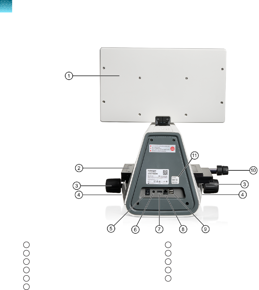
Rear view
1
LCD monitor
2
Mechanical X-Y stage
3
Focusing knobs
4
USB-A 3.0 port (2×)
5
Power switch
6
Single-pin power input port (12VDC, 5A)
7
DisplayPort (video output)
8
Network port
9
USB-A 2.0 ports (2×)
10
Stage X- and Y-axis positioning knobs
11
Instrument passwords sticker
Chapter2Product information
Instrument exterior components and mechanical controls
2
14
EVOS
™
M5000 Imaging System User Guide

Graphical user interface (GUI)
GUI layout
The GUI of the system consists of the Viewing area on the left and Capture and Review tabs and the
Settings and Virtual keyboard buttons on the right. Each tab and button opens the controls necessary
to execute the selected function.
1 2 3 4
5
6
1
Sign In/User: Allows you to sign in to your Connect account, Connect-based platform, for image storage and
analysis with the EVOS
™
Image Analysis application.
2
Viewing area: Displays the live or captured images of the sample.
3
Capture tab: Contains the controls for image capture.
4
Review tab: Allows you to review and annotate captured images.
5
Keyboard button: Opens the virtual keyboard.
6
Settings button: Opens the Settings tabs, which allow you to select and adjust basic and advanced system settings.
Note: For more information and detailed descriptions of GUI controls, see Appendix B, “Graphical user
interface (GUI)”
.
Note: For more information on the EVOS
™
Image Analysis application, see Appendix D, “EVOS
™
image
analysis”
.
Chapter2Product information
Graphical user interface (GUI)
2
EVOS
™
M5000 Imaging System User Guide
15

Installation
Operating environment and site requirements
•
The dimensions of the EVOS
™
M5000 Imaging System are 18×23×18in (46×59×46cm)
(W × H × D). The system requires a benchtop of approximately 36×36in(92×92cm).
•
If the system includes the optional EVOS
™
Onstage Incubator (Cat. No. AMC2000), then add 16in
(40 cm) to the width of the bench.
•
Allow at least 2 in (5 cm) of free space at the back of the instrument to allow for proper ventilation
and prevent overheating of electronic components.
•
Place the EVOS
™
M5000 Imaging System on a level surface away from vibrations from other pieces
of equipment. Tabletop centrifuges, vortex mixers, and other laboratory equipment can vibrate the
instrument during operation and interfere with instrument performance.
•
If possible, install the EVOS
™
M5000 Imaging System away from direct light sources such as
windows. Ambient light can enter the imaging path and aect the image quality.
•
Operating temperature range: 4°–32°C (40°–90°F).
•
Relative humidity range: 0–90%.
•
Operating power: 100–240 VAC, 1.8A
•
Frequency: 50–60Hz
•
Electrical input: 12VDC, 5A
IMPORTANT! Do not position the instrument so that it is
dicult to turn o the main power switch
located on the back of the instrument base (see “Rear view” on page14). In case of an instrument
malfunction, turn the main power switch to the OFF position and disconnect the instrument from the
wall outlet.
Cell culture hood setup
The EVOS
™
M5000 Imaging System
fits in cell culture hoods that are at least 24in (61cm) deep and
36 in (92 cm) high with a 30 in (76 cm) opening. If your cell culture hood is smaller, it may be possible to
fit the instrument by turning it at a slight angle.
3
16
EVOS
™
M5000 Imaging System User Guide

Prepare for installation
Receive and inspect the shipment
1.
Verify that the items shown on the shipping list are the same items that you ordered at the time of
purchase.
2.
Carefully inspect the shipping containers and report any damage to the Thermo Fisher Scientific
service representative. Record any damage or mishandling on the shipping documents.
Move the instrument to the installation site
1.
Clear the installation site of all unnecessary materials.
2.
If possible, move the crated instrument and other shipping containers to the installation site.
CAUTION! PHYSICAL INJURY HAZARD
. Lift or move the instrument using proper lifting
techniques. We recommend that you lift or move the crated instrument with the assistance of others
and the use of appropriate moving equipment. Improper lifting can cause painful and permanent back
injury. Depending on the weight, moving or lifting an instrument may require two or more persons.
Install the instrument
Unpack the instrument
1.
Open the shipping box and remove the accessory box.
2.
Carefully lift the instrument out of the box by grasping it firmly with both hands under the support
arm.
3.
Place the instrument on a flat, level surface that will be free from vibration and leave enough room
ar
ound it for the stage to move freely.
4.
Tilt the LCD monitor upright.
5.
Examine the instrument carefully for damage incurred during transit.
6.
Unpack the accessories box and verify all parts are present. See “Standard items included” on
page
11 for the list of standard items included in the shipment.
IMPORTANT! Do not subject the EVOS
™
M5000 Imaging System to sudden impact or excessive
vibration. Handle the instrument with care to prevent damage.
Note: Contact your distributor if anything is missing. If you do not have your distributor information,
contact T
echnical Support. Damage claims must be filed with the carrier; the warranty does not cover
in-transit damage.
Chapter3Installation
Prepare for installation
3
EVOS
™
M5000 Imaging System User Guide
17

Note: Make sure to set aside packaging and foam for future transport and storage. Re-install the stage
lock pin and the light cube shipping restraint before moving or transporting the instrument. Always
ensure that the instrument is properly cushioned and braced to prevent damage.
Remove shipping restraints
The EVOS
™
M5000 Imaging System is equipped with two shipping restraints (stage lock pin and light
cube shipping restraint) to protect the instrument from shock and vibration during transport. You must
remove the shipping restraints before you power on the EVOS
™
M5000 Imaging System.
2
3
1
Figure1Before removing the stage lock pin.
1
Stage lock pin
2
Light cube shipping restraint
3
Light cube tool
1.
Pull firmly to remove the stage lock pin.
2.
Using the Y-axis stage positioning knob, move the stage back to obtain access to the light cube
shipping r
estraint, which is centered under the back of the stage.
Note:
The light cube shipping restraint is secured with the light cube tool to the blank light cube
installed in the light cube turr
et. Used together, they immobilize the light cube turret to protect it
during transport.
Chapter3Installation
Install the instrument
3
18
EVOS
™
M5000 Imaging System User Guide

Figure2After removing the stage lock pin and moving the stage to access the shipping restraint.
3.
Unscrew and remove the light cube tool, which secures the shipping restraint block to the blank
light cube.
4.
Remove the shipping restraint block and store it in the accessories box. Removal of the restraint
block pr
ovides access to the blank light cube in the light cube turret.
Note:
The blank light cube is red and does not have the grooved copper top of the LED light
cubes.
1
Blank light cube
2
Thread hold
3
Screws
Chapter3Installation
Install the instrument
3
EVOS
™
M5000 Imaging System User Guide
19

5.
Using the light cube tool, loosen the two screws that secure the blank light cube to the instrument.
You do not need to remove the screws.
6.
Screw the light cube tool in to the threaded hole in the blank light cube, then lift the blank light
cube up and out of the micr
oscope. Store the blank light cube and the light cube tool in the
accessories box.
Note:
Store the shipping restraints and the light cube tool for future use in the accessories box
pr
ovided with your system. Always re-secure the X-Y stage with the stage lock pin and re-install the
light cube restraint before moving the instrument.
IMPORTANT! Before changing light channels, ALWAYS verify the light cube restraint has been
removed. Attempting to change the light channels while the restraint is in place can seriously damage
the mechanism. This type of damage is not covered by the manufacturer’s warranty.
Install the UV light shield
1.
Verify that the EVOS
™
Condenser Light Shield
™
is installed on the condenser assembly. The
condenser shield is pr
e-installed and helps reduce the potential eects of overhead lighting on
your image.
2.
Pull the condenser light shield out from the condenser head.
Chapter3Installation
Install the instrument
3
20
EVOS
™
M5000 Imaging System User Guide

3.
Secure the UV light shield mount to the top of the condenser light shield using the two screws and
2 mm hex key supplied with the UV shield assembly (not the protruding screws on the mount).
4.
Clip the condenser light shield with the attached UV light shield mount back onto the condenser
head.
5.
Peel the protective paper from the UV light shield, then slide the orange UV light shield over the
two pr
otruding screws on light shield mount to attach it to the instrument.
Chapter3Installation
Install the instrument
3
EVOS
™
M5000 Imaging System User Guide
21

Note: The UV light shield is provided as a safety feature and should be installed whenever the unit is in
operation. The UV light shield is removable for access to the condenser sliders used in transmitted light
mode. Simply unhook it from the screws on the UV light shield mount.
Connect the instrument
1.
Confirm that the power switch is OFF (located on the back; see “Rear view” on page14).
2.
Connect the USB receiver for the wireless mouse
(locat
ed inside the flap of the mouse box) and
keyboard to an available USB-A 2.0 port (“Rear view”
on page14).
3.
Connect
the power adaptor and power cord. Ensure a tight connection
4.
Plug the power adaptor into the power input port on the instrument (“Rear view” on page14).
5.
Plug the power cord into a power outlet and check for the light on the power supply.
Turn on the EVOS
™
M5000 Imaging System
1.
Turn the instrument power switch (located on the back; see “Rear view”
on page14) to the ON
position.
2.
When the Capture tab is displayed, the EVOS
™
M5000 Imaging System is ready to use.
Connect the instrument to the internet
You can connect the EVOS
™
M5000 Imaging System to a network via an Ethernet cable or Wi-Fi
adapt
or and save captured images directly to shared folders on the network. You can also connect to
your Connect
account, Connect-based platform, to store your image files and analyze them with the
EV
OS
™
Image Analysis application (“EVOS
™
image analysis” on page
138).
For instructions on how to connect to a Wi-Fi network and how to map a network drive for saving your
images, see “Configure network settings” on page102.
Set date and time
For instructions on how to configure the date and time to the local time, see “Set date and time” on
page105.
Chapter3Installation
Turn on the EVOS
™
M5000 Imaging System
3
22
EVOS
™
M5000 Imaging System User Guide

Connect to the Thermo Fisher
™
Connect Platform
About the Thermo Fisher
™
Connect Platform
The Thermo Fisher
™
Connect Platform enables access to your EVOS
™
M5000 instrument through
Instrument Connect by way of a web browser or mobile device. Connecting to your Connect account
allows you to save captured images in your unique user account in addition to local storage.
Create a Connect account
1.
Go to thermofisher.com/connect from your web browser.
2.
Click
Sign up now and follow the prompts to create an account.
Your e-mail address is used as your username.
3.
When signed in, click Update PIN number.
4.
Enter a PIN number in the
new and confirm fields.
The PIN number is necessary to sign in to Connect
from the instrument.
Create a PIN number
1.
Log in to your Connect account using a web browser.
2.
Navigate to
(Instrument Connect).
3.
Select Update PIN number.
4.
Confirm
the PIN number.
Chapter3Installation
Connect to the Thermo Fisher
™
Connect Platform
3
EVOS
™
M5000 Imaging System User Guide
23

Link instrument to your Connect account
You can link the EVOS
™
M5000 instrument to your Connect account using one of the following options:
1.
Mobile Device (QR code): Scan the QR code on your instrument using the Instrument Connect
application on your mobile device (“Add instrument to your Connect account with QR code (Mobile
Device)” on page25).
2.
PC (linking code): Obtain a linking code to enter online in Thermo Fisher
™
Connect Platform (“Add
instrument to your Connect account with QR code (Mobile Device)” on page25).
When the instrument is linked, you can save captured images in your unique user account in
addition t
o local storage.
IMPORTANT! The first Connect
account that links to the instrument becomes Administrator by
default. If the first user needs to be unlinked from the instrument, a new user must be assigned
the Administrator role beforehand. Failure to do so will result in the loss of instrument connectivity
for all other linked users. For instructions on how to setup a new Administrator see “Set up a new
administrator” on page26.
Chapter3Installation
Connect to the Thermo Fisher
™
Connect Platform
3
24
EVOS
™
M5000 Imaging System User Guide

Add instrument to your Connect account with QR code (Mobile Device)
1.
Click (Sign In) on the top left corner of the screen to open the Sign In dialog.
2.
Click
Link Account, then select Mobile Device.
3.
Scan the QR code on your instrument using the Instrument Connect
application on your mobile
device.
Add instrument to Thermo Fisher
™
Connect Platform with linking code (PC)
1.
Click (Sign In)
on the top left corner of the screen to open the Sign In dialog.
2.
Click
Link Account, then select PC. Note the linking code provided by the instrument.
3.
Log in to your Connect
account using a web browser.
4.
Select
(InstrumentConnect
) from the left navigation strip.
5.
Select
(Add an Instrument) from the top navigation strip.
6.
Select
EVOS
™
M5000 from the Instrument type dropdown menu, then click Next
.
7.
Enter the linking code generated by the instrument in the text box, then click Send
.
Upon successful authentication, the instrument is linked to Connect
.
Sign in to your Connect account from the EVOS
™
M5000instrument
1.
Click
(Sign In)
on the top left corner of the screen to open the Sign In dialog.
Note:
If another user account is displayed, select the username to sign out and connect a dierent
user account.
2.
Select your user name from the list of linked accounts in the Username dropdown.
Chapter3Installation
Connect to the Thermo Fisher
™
Connect Platform
3
EVOS
™
M5000 Imaging System User Guide
25

3.
Enter your Connect PIN number.
If you do not have a PIN number, set the PIN number in the Instrument Connect application
(“Create a PIN number” on page23).
4.
Click
Sign In.
When you connect to your Connect
account, the
Sign In button changes to display your user
name (for example,
).
5.
To sign out of your Connect
account, click your User button to open the Sign Out dialog, then
click Sign Out.
Note: You can choose to save captured images to your Connect account in addition to local storage.
Images saved t
o your Connect
account can then be viewed and analyzed with the online EVOS
™
Image
Analysis application.
For more information on the online EVOS
™
Image Analysis application, see Appendix D, “EVOS
™
image
analysis”
.
Set up a new administrator
1.
Log the current Administrator into their Connect account.
2.
Select Instruments.
3.
Select the EVOS
™
M5000 instrument the user is linked to.
4.
Select Manage users from the top navigation strip.
5.
Set Administrator privileges to another user linked to the same instrument.
Chapter3Installation
Connect to the Thermo Fisher
™
Connect Platform
3
26
EVOS
™
M5000 Imaging System User Guide


Capture tab
The basic functions of the EVOS
™
M5000 Imaging System, such as viewing the sample, setting optimal
focus, and capturing and saving images are performed in the Capture tab, which is the first screen after
start-up.
Capture images in a single channel
Select objective and light source
1.
Place the vessel containing your sample on the stage using the appropriate vessel holder.
Note: When capturing images in fluorescence channels, place the light shield box on the stage,
over the sample. This is important for optimal image quality.
2.
Set the
magnification using the objective selection wheel (“Front view” on page13).
3.
Select the desired
Phase option by turning the phase ring selector (“Front view” on page13).
Available options are:
•
Oly 4x: Used for Olympus
™
4x phase contrast objectives (Olympus
™
4x PH)
•
4x/10x: Used for EVOS
™
4x or 10x phase contrast objectives (EVOS
™
4x/10x PH)
•
20x/40x:
Used for EVOS
™
20x or 40x phase contrast objectives (EVOS
™
20x/40x PH)
•
Brightfield (phase contrast o)
The active objective and phase ring information is displayed above the Channel buttons.
Chapter4Capture images
Capture images in a single channel
4
28
EVOS
™
M5000 Imaging System User Guide

1
2
3
1
Memory
buer thumbnail images
2
Auto-capture channels (via the All
button)
3
Channel selection/light activation buttons
Note: If the phase ring correctly matches the objective, the selected phase ring is depicted in
blue. If the objective and the phase ring ar
e mismatched, the phase ring (Condenser) is displayed
in orange.
4.
Select a
Channel to turn on the excitation light and set the instrument in Live mode.
In the Live mode, you can adjust the brightness, configure display settings for the selected
channel, and set the focus on the sample.
Note:
You can only select a single light source for
Live mode when adjusting brightness and
focus. However, you can capture and display multiple channels sequentially.
Adjust brightness
Brightness is controlled with the use of Light, Exposure, and Gain slider bars in the Capture control
panel. Selecting one of the two Brightness slider panels enables control of the brightness settings.
•
Select the single slide panel to adjust the Light setting and allow the system to automatically
det
ermine the camera Exposure and Gain settings to minimize photobleaching.
•
Select the triple slider panel to individually adjust the Light, Exposure, and Gain settings.
Chapter4Capture images
Capture images in a single channel
4
EVOS
™
M5000 Imaging System User Guide
29

Note: Optimize the brightness parameters as follows:
·
For brighter signal: Increase Light intensity for brighter illumination. If needed, follow by increasing
Gain.
·
For time-lapse imaging: Increase Gain and Exposure, decrease Light intensity to reduce
photobleaching and phototoxicity.
For example, for overnight time-lapse experiments, capture one image every 30 minutes or longer,
limit the use of autofocus, and use a channel other than DAPI for autofocus.
·
In the Settings4Display tab, select Highlight Saturated Pixels to display the overexposed pixels in
the color of your choice. To obtain the maximum level of brightness without any overexposed areas,
dim the illumination until the highlights disappear.
Focus on the sample
1.
Use the Coarse and Fine focus sliders to focus on the sample.
Alternatively, click AutoFocus to autofocus on the sample.
2.
To limit the autofocus algorithm to a specific region along the Z-axis, use the Autofocus Maximum
and Autofocus Minimum
controls (blue triangles on the Coarse focus slider) to set the upper and
lower bounds.
Note:
You can also focus on the sample manually using the focusing knobs on the instrument
(
“Front view” on page13).
Note: Do NOT use autofocus with oil-immersion objectives, as this can create air bubbles in the
oil or cause the objective t
o collide with the sample.
3.
Repeat the focus procedure for each channel you want to capture.
4.
To preserve the Z-Osets between the channels, select Sync Z.
Click next to the
Sync Z selection as a reminder of how Sync Z aects the focusing.
•
When synched, focus adjusts for all channels.
•
When unsynched, focus only adjusts the selected channel.
Chapter4Capture images
Capture images in a single channel
4
30
EVOS
™
M5000 Imaging System User Guide
Note: Z-Oset specifies the focus position in the selected channel relative to the focus position in
other channels. Setting the correct Z-Oset is especially important when the fluorescent markers in
dierent channels are in dierent focal planes.
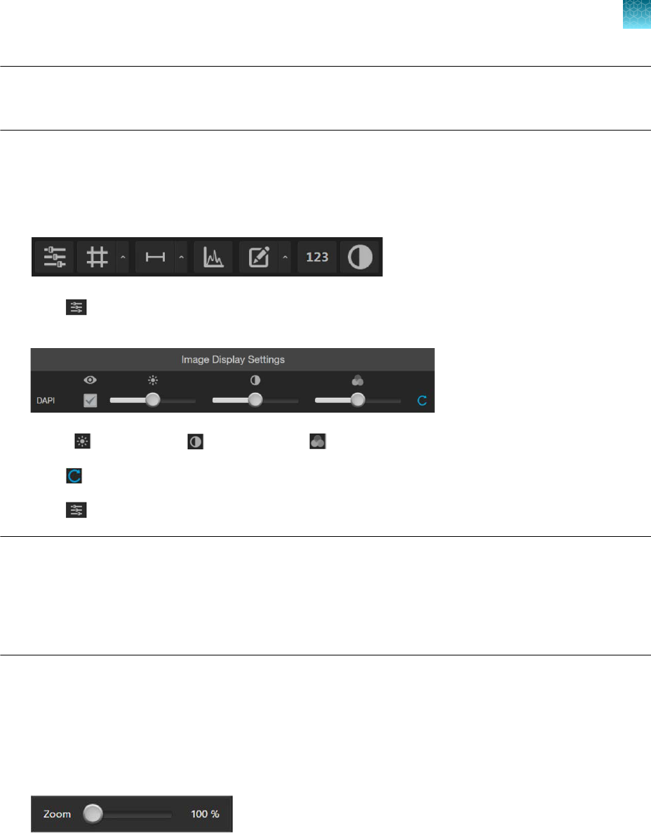
Optional: Adjust display settings
1.
If not already visible, hover the pointer over the Viewing area to reveal the buttons for Display
Settings and Analysis Tools.
2.
Click (Image Display Settings)
to expand the controls for image display settings for the
selected channel.
3.
Adjust (Brightness) , (Contrast), and (Gamma) using the corresponding sliders.
4.
Click (Reset) to return the display settings to their default values.
5.
Click (Image Display Settings)
again to collapse the controls.
Note:
The
Gamma slider allows non-linear contrast adjustments; moving it to the left suppresses
low intensities whereas moving it to the right boosts low intensities. For images with nonspecific
background fluorescence (often called "autofluorescence") moving the Gamma slider to the left may
help reduce undesired background fluorescence. For images with very faint fluorescence signals,
moving the Gamma slider to the right may help increase faint signals and bring them out of the
background, making them easier to see or detect at the lower limits of brightness.
Find a region of interest
1.
Use the
X-axis and Y-axis positioning knobs (“Front view” on page13) to move the sample stage
and bring the region of interest into the field of view.
2.
To zoom in and out of the Viewing area, use the Zoom slider. The zoom range is 100–1000%.
You can also double-click on the image to center and zoom by 200% on the clicked location, to a
maximum of 1000%. Right-clicking on a zoomed image r
esets the zoom to 100%.
3.
If needed, readjust the brightness and focus, then proceed to capture the image.
Chapter4Capture images
Capture images in a single channel
4
EVOS
™
M5000 Imaging System User Guide
31

Capture images for each channel
1.
Ensure that the Channel you want to capture is selected.
When you select a Channel, the corresponding Capture channel checkbox above the button is
aut
omatically checked.
Note:
If you exit the Live mode, the current channel remains selected, as indicated by the
highlight
ed color surrounding the channel button.
2.
Click
Capture to acquire the image.
The viewing area shows the newly captured image.
A thumbnail of the captured image is displayed and highlighted for the selected channel (in this
e
xample, DAPI) beneath the Objective display.
IMPORTANT! Captured images are stored in individual memory buers with one for each
channel. Memory buers are for display and are not automatically saved. If unsaved, newly
captured images overwrite the previously captured image in the selected channel. Images
captured in other fields and channels are not aected.
3.
To capture the same field of view in another channel, select the desired Channel (for example,
GFP
, TX RED, etc.).
Chapter4Capture images
Capture images in a single channel
4
32
EVOS
™
M5000 Imaging System User Guide

4.
If needed, readjust the brightness and focus, then click Capture.
The viewing area shows the image captured in the new channel superimposed on the image
captured in the previous channel.
A thumbnail of the image captured in the new channel is displayed along with the thumbnail of the
image fr
om the previously captured channel.
Repeat the above steps to capture each channel as needed.
5.
To remove a captured image from the memory buer, click the
X on the desired image, then click
the X again to remove only the selected image. To remove all captured images from the memory
buer, click the X on any of the captured images, then click
All(Clear All).
Chapter4Capture images
Capture images in a single channel
4
EVOS
™
M5000 Imaging System User Guide
33

Capture images in multiple channels
Capture multiple channels automatically
1.
To capture multiple channels automatically, select the desired channels by checking the
corresponding boxes.
2.
If needed, adjust brightness and focus for each of the selected channels as described.
3.
Click
All to automatically acquire an image in each of the selected channels.
The Viewing area shows a multicolor overlay of the images captured for each selected channel.
A thumbnail of the captured image is displayed for each captured channel (in this example, DAPI,
GFP, and Texas Red
™
).
Chapter4Capture images
Capture images in multiple channels
4
34
EVOS
™
M5000 Imaging System User Guide

IMPORTANT! Captured images are stored in individual memory buers with one for each
channel. Memory buers are for display and are not automatically saved. If unsaved, newly
captured images overwrite the previously captured image in the selected channel. Images
captured in other fields and channels are not aected.
4.
To remove a captured image from the memory buer,
click the X on the desired image, then click
the X again to remove only the selected image. To remove all captured images from the memory
buer, click the X on any of the captured images, then click
All (Clear All).
Chapter4Capture images
Capture images in multiple channels
4
EVOS
™
M5000 Imaging System User Guide
35

Measure, annotate, and analyze
captured images
Display settings and analysis tools
Display settings and analysis tools allow you to change image display settings for live and captured
images in the Viewing area, correct pixel shifts that can occur at higher magnifications in multichannel
fluorescent images, annotate captured images, and perform cell count, measure confluence, and
calculate transfection eciency.
1.
If not already showing, hover the pointer over the Viewing area to reveal the buttons for Display
Settings and Analysis Tools.
Note: Display Settings and Analysis Tools
is available in both the Capture and Review tabs.
2.
Click a button to open the corresponding tool; click the button again to close it. Using the Display
Settings and Analysis Tools, you can:
•
Configure
display settings (“Configure display settings” on page88)
–
Adjust image display settings (“Adjust image display settings” on page37)
–
Display a grid (“Display grid” on page38)
–
Display a scale bar (“Display scale bar” on page39)
•
Align channels (“Align channels” on page40)
Note:
The button to display the Align Channels
tool (indicated by the red arrow) is visible
only if the Show Align Channels in Display Settings and Analysis Tools option is selected in
the Settings4General tab (“Show Align Channels tool” on page102).
•
View pixel intensity histogram (“View pixel intensity histogram” on page41
)
•
Add and show measurements and annotations (“Add measurements and annotations” on
page42)
5
36
EVOS
™
M5000 Imaging System User Guide

•
Analyze cell culture (“Analyze cell culture” on page44):
–
Perform Auto Count (“Perform auto count” on page45)
–
Perform Manual Count (“Perform manual count” on page51)
–
Measure confluence (“Measure confluence” on page54)
–
Calculate transfection eciency (“Calculate transfection eciency” on page58)
•
Save analysis results (“Save analysis results” on page92)
IMPORTANT! Changes made to images in the Viewing area with the display settings and analysis
tools, including changes made to image parameters, display of the grid and the scale bar, as well
as any annotations and measurements, are part of any saved display image. In contrast, saved
analysis images (that is, 16-bit individual channel files) consist of the raw data and do not preserve
any edited changes.
To save raw image data for image analysis, select the Save individual channels for analysis
option when saving captured images (“Save” on page62).
Adjust image display settings
1.
Click (Image Display Settings) to expand the controls for image display parameters
(Brightness, Contrast, Gamma) for captured images.
Note: The controls for Image Display Settings are contextual; they are available only for channels
with captur
ed images or for a single channel in the Live mode (with the illumination light turned
on). In the example above, only the controls for DAPI, GFP, and TX Red channels are displayed.
2.
(
Optional): To remove a channel from displaying in the Viewing Area, unselect the corresponding
checkbox.
To display a channel with a captured image that is not shown in the Viewing Area, reselect the
checkbox.
3.
Adjust the
(Brightness), (Contrast), and (Gamma) settings for each of the selected
channels using the corr
esponding sliders.
4.
Click
(Reset) to return the image display settings to their default values.
5.
Click
(Image Display Settings) again to collapse the controls.
Note: The Gamma slider allows non-linear contrast adjustments. Moving the slider to the left
suppresses low intensities. Moving the slider to the right boosts low intensities. For images with
nonspecific background fluorescence (also known as autofluorescence), moving the Gamma slider to
Chapter5Measure, annotate, and analyze captured images
Adjust image display settings
5
EVOS
™
M5000 Imaging System User Guide
37

the left may help reduce undesired background fluorescence. For images with very faint fluorescence
signals, moving the Gamma slider to the right may help the intensity of faint signals to stand out from
the background. This can help to see or detect signals at the lower limits of brightness..
Display grid
1.
Click (Grid) to superimpose a grid over the Viewing area.
2.
To change the grid size, click (Grid Settings)
(arrow on the Grid split button) to open the Grid
Settings tool.
3.
Select the Size for the grid. Available grid sizes depend on the magnification of the selected
objective. Also pr
ovided is the option to display the center point to identify the center of the field of
view.
4.
Click the
Grid Settings button again to save your settings and close the tool.
Chapter5Measure, annotate, and analyze captured images
Display grid
5
38
EVOS
™
M5000 Imaging System User Guide

Display scale bar
1.
Click (Scale Bar) to superimpose a scale bar over the Viewing area.
2.
To change
Scale Bar Settings, click
(Scale Bar Settings) (arrow on the Scale Bar split
butt
on) to open the Grid Settings tool.
3.
Select
Show End Bars to display the scale bar with the end bars.
4.
Select the Color
for the scale bar.
5.
To move the scale bar, hover your pointer over the scale bar until a bounding box appears, then
click within the bo
x and drag the scale bar to the desired location within the Viewing area.
6.
To adjust the length of the scale bar, hover your pointer over the scale bar until a bounding box
appears, then the click left or right side of the bo
x and drag the box to the desired length.
You can adjust the length by pre-fixed increments based on the objective magnification.
7.
Click (Scale Bar Settings) again to save your settings and close the tool.
Chapter5Measure, annotate, and analyze captured images
Display scale bar
5
EVOS
™
M5000 Imaging System User Guide
39

Align channels
Align channels
The Align Channels tool allows you to correct pixel shifts that can occasionally appear when
performing multichannel fluorescence imaging at higher magnifications. You can select individual
channels in a multichannel image, move them to the correct position relative to other channels, and
then save the corrected image.
Note: The button to display the Align Channels tool is visible only if the Show Align Channels in
Display Settings and Analysis Tools option is selected in the Settings4General tab (“Show Align
Channels tool” on page102).
1.
Click (Align Channels) to expand the controls for the Align Channels tool.
Note: The controls for the Align Channels tool are contextual. The tool only displays the controls
for the channels in which the select
ed multichannel fluorescent image has been captured. In this
example procedure, the multichannel image was captured in the DAPI and GFP channels.
2.
Select the channel for which you wish to correct pixel shifts. In the following example, the GFP
channel is select
ed.
3.
Optional
: To remove a channel from displaying in the Viewing Area, unselect the corresponding
View checkbox. To display a channel with a captured image that is not shown in the Viewing Area,
re-select the corresponding View checkbox.
4.
Use the keyboard arrow keys to move the image in the selected channel to the desired position to
corr
ect for the pixel shift.
Chapter5Measure, annotate, and analyze captured images
Align channels
5
40
EVOS
™
M5000 Imaging System User Guide

5.
If the multichannel image was captured in more than two channels, repeat the process for the
other channels until all the channels are correctly aligned.
6.
Click
Save to save the corrected image, then click the Align Channels button to hide the channel
alignment controls.
View pixel intensity histogram
Display histogram
1.
Click (Histogram) to open the Intensity Histogram plot.
2.
The Pixel Intensity histogram shows the Pixel count vs. Intensity data of the image displayed in the
Viewing area as well as the minimum, mean, and maximum pixel intensities.
Chapter5Measure, annotate, and analyze captured images
View pixel intensity histogram
5
EVOS
™
M5000 Imaging System User Guide
41

3.
To move the histogram, click within the plot heading area and drag the plot to the desired location.
4.
To resize the histogram, click the grey triangle at the lower right corner of the plot, then drag the
plot t
o the desired size.
5.
Click the
Histogram button again to close the Pixel Intensity histogram.
Alternatively, click the X on the plot window to close the histogram.
Add measurements and annotations
1.
Click (Measurement and Annotations) (the arrow on the Show Measurements and
Annotations split button) to open the measurement and annotations tools.
2.
Using the
Annotations tools, draw a rectangle, line, ellipse, polygon, or a free-form shape over
the region of interest on the Viewing area. You can draw multiple shapes of dierent types.
3.
If needed, change the Color
and Thickness of the annotation to make it more visible over the
image.
Chapter5Measure, annotate, and analyze captured images
Add measurements and annotations
5
42
EVOS
™
M5000 Imaging System User Guide

4.
If desired, choose to display the Dimensions, Area, or Perimeter information for the selected
annotation from the dropdown menu.
5.
To delete a selected annotation, click the
X on the shape that appears when you hover your pointer
over it.
To delete all annotations, click Reset, then click OK in the dialog that opens.
6.
Click the
Measurement and Annotations Tools button (arrow on the split button) again to close
the tools.
7.
After you have added measurements and annotations to your image:
•
Click
Show Measurements and Annotations (main part of the split button) to turn the display
on and o.
•
Click Measurement and Annotations Controls (the arrow on split button) to display the
controls to add new measurement and annotations or to delete existing ones.
Chapter5Measure, annotate, and analyze captured images
Add measurements and annotations
5
EVOS
™
M5000 Imaging System User Guide
43

Analyze cell culture
Analysis tools
If not already showing, hover the pointer over the Viewing area to reveal the Display Settings and
Analysis Tools toolbar, then click (Show Cell Count) to display Auto Count, Manual Count, and
Cell Culture options in the tabs area.
Note: Display Settings and Analysis Tools is available in both the
Capture and Review tabs.
•
Auto Count
: Automatically counts the objects displayed in the Viewing area based on your
specifications (“Count cells – auto count” on page45). With Auto Count, you can count objects
only in a single fluorescence channel (nuclear stain channel).
•
Manual Count: Allows you to tag objects in the Viewing area with up to six labels. As you tag
objects, the system keeps a running tally of the counts with percentages for each label assigned
(“Count cells – manual count” on page51). With Manual Count, you can count objects in multiple
channels simultaneously.
•
Cell Culture: Allows you to measure the confluence of your culture and calculate the transfection
eciency.
–
Confluence: Allows you to select up to five reference objects for the target (for example, cells)
and one background reference in your image, then automatically calculates the percentage of
confluence of your culture (“Count cells – manual count” on page51).
–
Transfection Eciency: Allows you to estimate the transfection eciency of your culture by
calculating the ratio of fluorescence area (i.e., cells expressing the fluorescence marker) to the
total cell area in your culture (“Calculate transfection eciency” on page58).
•
Batch Analysis: Allows you to save and apply the analysis parameters set in the Auto Count,
Confluence, and Transfection Eciency tools to other images that you have collected and saved
an image folder (“Batch analysis” on page94). Batch Analysis is not available for Manual Count.
IMPORTANT! For analysis, only use 16-bit image files
(TIFF or PNG). The 16-bit images of individual
channels contain the full dynamic range and metadata needed for quantitative analysis, whereas display
image files do not.
Chapter5Measure, annotate, and analyze captured images
Analyze cell culture
5
44
EVOS
™
M5000 Imaging System User Guide

Count cells – auto count
Perform auto count
1.
Click (Show Cell Count), then select Auto Count.
2.
If counting from the Capture tab, select the
Channel in which to count objects.
Available options depend on the channels used when the image was captured. In this example, all
channels contain captured images, and DAPI is selected for auto count.
Chapter5Measure, annotate, and analyze captured images
Count cells – auto count
5
EVOS
™
M5000 Imaging System User Guide
45

3.
To identify targets, click Target, then click and drag to draw a circle (blue) around a representative
target.
4.
If needed, click Target again to identify other targets (for example, nuclei that might appear
dierent) to improve the accuracy of your count.
Note: For best results, follow these guidelines when identifying target objects:
·
When selecting objects, circle the entire object and include a slight border around it.
·
To include objects of lower intensity in your count, select dimmer objects during identification.
·
Circle only one object at a time to help define object size for segmentation.
Chapter5Measure, annotate, and analyze captured images
Count cells – auto count
5
46
EVOS
™
M5000 Imaging System User Guide

5.
To distinguish the target from background, click Backround, then click and drag to draw a circle
(orange) in a background area.
6.
After you define the target and background areas, the software automatically counts the objects
based on your crit
eria.
Chapter5Measure, annotate, and analyze captured images
Count cells – auto count
5
EVOS
™
M5000 Imaging System User Guide
47

The target objects that were counted are identified with colored circles (in this example, yellow)
and the Object Count field displays the number of objects included in the count.
Note: Depending on the quality of the image and representative targets and background that you
have select
ed, the auto count algorithm can overcount or undercount the cells in the image.
Figure3Undercount – 2 cells counted as 1
Figure4Overcount – 1 cell counted as 2
To obtain a more accurate count:
·
Split cells by shape or intensity.
·
Refine your count by intensity, area, or circularity.
Chapter5Measure, annotate, and analyze captured images
Count cells – auto count
5
48
EVOS
™
M5000 Imaging System User Guide

7.
To count closely grouped cells that are touching or overlapping as distinct objects, select from the
Split Cells options:
•
None:
Touching or overlapping objects are not counted separately.
•
Shape: Distinct objects are identified and counted based on shape.
•
Intensity: Distinct objects are identified and counted based on pixel intensity.
8.
The
Refine section displays a histogram plot showing Count versus Intensity, Area, or Circularity.
In this example, Intensity is selected.
9.
To
refine your count, select Intensity, Area, or Circularity, move the gate handles to set the upper
or the lower boundary for the selected parameter.
You can refine the count by a single parameter or by multiple parameters.
The software applies the selected boundaries and recalculates the count.
Chapter5Measure, annotate, and analyze captured images
Count cells – auto count
5
EVOS
™
M5000 Imaging System User Guide
49

10.
To change the color of the circles that identify the objects included in the count, select the desired
color from the Count Color dropdown.
11.
When
finished with the count, save your count results (see “Save analysis results” on page92).
IMPORTANT! If you navigate away from the Auto Count screen, your count will be lost. To preserve
the count results, make sure to save it before you navigate away from the count screen.
Chapter5Measure, annotate, and analyze captured images
Count cells – auto count
5
50
EVOS
™
M5000 Imaging System User Guide

Count cells – manual count
Perform manual count
1.
Click (Show Cell Count), then select Manual Count.
2.
Select the
Channels to display in the Viewing area for manual count. You can select multiple
channels that contain captured images.
In this example, DAPI and RFP channels contain captured images, and both are selected for the
manual count.
Chapter5Measure, annotate, and analyze captured images
Count cells – manual count
5
EVOS
™
M5000 Imaging System User Guide
51

3.
Click in an Object Name field to enter a name for that label. You can use up to six labels to tag
objects for the manual count.
Chapter5Measure, annotate, and analyze captured images
Count cells – manual count
5
52
EVOS
™
M5000 Imaging System User Guide

4.
Click on the Label number to select a label, then left-click at each point on the Viewing area to tag
the items in that label category. You can switch labels as desired.
As you tag the objects onscreen with the selected label, the system keeps a running tally of the
counts with per
centages for each label assigned.
Chapter5Measure, annotate, and analyze captured images
Count cells – manual count
5
EVOS
™
M5000 Imaging System User Guide
53

5.
To delete a tag, right-click on the tag you wish to delete
6.
To delete all tags for a label, check the
Delete box for the label, then click the Trash button.
7.
To delete all tags for all labels, check the Delete
boxes for each label, then click the Trash button.
8.
When
finished with the count, save your count results (see “Save analysis results” on page92).
Measure confluence
Confluence
tool
Confluence is a measure of how densely cells are distributed in culture. When all available growth area
is utilized in a culture vessel and the cells make close contact with one another, the culture is at 100%
confluence.
The Confluence tool measures the percent area covered by cells in the image, which is required to
calculate transfection eciency.
Guidelines for confluence measurements
•
We recommend that you visualize your cells using transmitted light and a phase objective with 4x
to 10x magnification. Set the phase ring to Oly 4x (for Olympus
™
4x phase objective) or 4x/10x
(for
EVOS
™
phase objectives) using the phase ring selector (“Front view” on page13).
•
If you plan to calculate the transfection eciency after measuring the confluence, capture the
image in both the tr
ansmitted light channel and the fluorescence channel for the marker that your
cells are expressing.
•
For analysis, only use 16-bit image files (TIFF or PNG), which contain the full dynamic range and
metadata needed for quantitative analysis.
•
Increasing the number of targets and background areas improves accuracy. You can select up to 5
target areas and 5 background areas.
•
The Confluence tool uses a texture and intensity-based algorithm. The sensitivity slider adjusts
the algorithm sensitivity to pixel intensity (higher intensity = more pixels included). Decreasing the
sensitivity reduces the confluence value.
•
Dierent cell types have dierent confluence “patterns”, and variability in morphology and contrast
can influence the absolute confluence measurement between dierent cell types. However, within
a given cell type, you can optimize the reproducibility of your measurements. Reproducibility in
confluence measurements is more important than absolute percentages.
Measure confluence
1.
In the transmitted light channel, adjust lighting and focus on the sample, then click Capture to
acquire an image of your culture.
Note:
If you plan to calculate the transfection eciency after measuring the confluence, capture
the image in both the tr
ansmitted light channel and the fluorescence channel for the marker that
your cells are expressing.
Chapter5Measure, annotate, and analyze captured images
Measure confluence
5
54
EVOS
™
M5000 Imaging System User Guide

2.
If not visible, hover the pointer over the Viewing area to reveal Display Settings and Analysis
Tools, then click the Show Cell Count (123) button.
3.
In the tabs area, select Cell Culture to display the Confluence tool.
4.
Click
Target, then click and drag on the image to draw a circle around an area that contains cells
(blue circle).
Chapter5Measure, annotate, and analyze captured images
Measure confluence
5
EVOS
™
M5000 Imaging System User Guide
55

5.
Click Background, then click and drag on the image to draw a circle around a background area
that does not contain any cells (orange circle).
Note: You can select up to 5 targets and 5 background areas. Increasing the number of targets
and backgr
ound areas improves the accuracy and reproducibility of the confluence measurements.
6.
The software automatically calculates the
confluence of your culture and displays the results as a
percentage.
Chapter5Measure, annotate, and analyze captured images
Measure confluence
5
56
EVOS
™
M5000 Imaging System User Guide

7.
To view the areas of the image counted as Target, select Show Mask. The areas counted as Target
are highlighted in the selected color.
8.
Refine
the sensitivity of the Confluence measurement using the Sensitivity slider. Increased the
sensitivity results in higher confluence value.
The software automatically calculates the
confluence of your culture and displays the results as a
percentage of confluence.
Note:
As you adjust sensitivity, observe the image with the Show Mask option on. Ensure that the
tar
get areas are selected with minimal coverage of the background areas.
9.
When you complete the confluence measurement, the Transfection Eciency tool becomes
available. To calculate transfection eciency, go to “Calculate transfection eciency” on page58.
10.
To save your Confluence results without calculating transfection eciency, click Save (see “Save
analysis results” on page
92).
Chapter5Measure, annotate, and analyze captured images
Measure confluence
5
EVOS
™
M5000 Imaging System User Guide
57

Calculate transfection eciency
Transfection Eciency tool
Transfection of a cell population typically results in a varying number of cells expressing the desired
genes of interest. Transfection eciency is the percentage of cells that are transfected compared to the
entire population.
The Transfection Eciency tool calculates the fluorescence area (transfected cells expressing the
fluorescence marker) divided by the entire cell area in the image.
IMPORTANT! For analysis, only use 16-bit image files
(TIFF or PNG), which contain the full dynamic
range and metadata needed for quantitative analysis.
Calculate transfection eciency
1.
After you have completed the
confluence measurement, click Transfection Eciency to expand
the controls for the Transfection Eciency tool.
2.
Select the
Fluorescence Channel for which you wish to calculate the transfection eciency.
In this example, we want to calculate the percentage of cells that express GFP. Therefore, the
GFP channel is selected. For display options, Fluorescence Channel and the Transmitted Light
Channel options are checked, so that both channels are displayed in the viewing area.
Chapter5Measure, annotate, and analyze captured images
Measure confluence
5
58
EVOS
™
M5000 Imaging System User Guide

The software automatically calculates the
Transfection Eciency and displays the results as
%Confluence and % Transfection Eciency.
Note:
The
Transfection Eciency calculation is based on the final measured confluence (Step 8
on page57) and the fluorescence area that is above the set fluorescence threshold value. To refine
the Transfection Eciency calculation, adjust the Threshold such that only the cells that express
at the desired level are included in the calculation (see step 5 on page61).
Chapter5Measure, annotate, and analyze captured images
Measure confluence
5
EVOS
™
M5000 Imaging System User Guide
59

3.
To view the pure fluorescence signal and to observe the various levels of fluorescence marker
(GFP) expression, uncheck the Transmitted Light Channel.
4.
Select
Threshold Mask to highlight the fluorescence areas included in the Transfection Eciency
calculation.
Chapter5Measure, annotate, and analyze captured images
Measure confluence
5
60
EVOS
™
M5000 Imaging System User Guide

5.
To refine the Transfection Eciency calculation, adjust the Threshold slider until all the cells that
express at the desired level are included in the calculation.
Note: Viewing the image only in the Fluorescence Channel
and toggling the Threshold Mask on
and o will help you determine the best Threshold value for your experiment.
As you adjust the Threshold, the software updates the calculation and displays the new
T
ransfection Eciency value.
6.
To save your Confluence and Transfection
Eciency results, go to “Save analysis results” on
page92.
Chapter5Measure, annotate, and analyze captured images
Measure confluence
5
EVOS
™
M5000 Imaging System User Guide
61

Save captured images
Save
Save images manually
1.
After capturing an image in a single channel or a set of images in multiple channels, click Save to
open the Save dialog, then navigate to the destination folder to save your captured images.
2.
Enter a new file
name for your saved images or use the default file name, then select the file format
from the Save as type dropdown.
Available
file formats are PNG, TIFF, and JPEG.
3.
Select
Save to cloud to save a copy of your captured image to your Connect
account.
To save the copy of your image to another account in the Connect platform, click
Switch Account,
then sign in to the appropriate account.
6
62
EVOS
™
M5000 Imaging System User Guide

4.
Select Save individual channels to save images captured in dierent channels individually. Saving
as type TIFF or PNG are the recommended formats for image analysis.
Leave the Save individual channels option unselected to save only the captured image displayed
in the viewing area. The image is saved in display format, which is not useful for analysis.
IMPORTANT! Save individual channels as type TIFF or PNG as these are the recommended
formats for image analysis, because they allow you to save raw image data from each selected
channel.
5.
Select
Save screenshot to save an image of the entire instrument screen in addition to the
captured image.
Leave the Save screenshot option unselected to save only the captured image.
Note:
Save screenshot
allows you retain an image of the annotations and image display
selections as seen in the viewing area along with the instrument controls.
6.
Click
Save to save the image.
Quick Save images
(Optional)
Enable Quick Save
Quick Save function allows you to set the save options in advance and save your captured images
with a single click directly from the Capture tab or automatically without having to click Save after each
capture.
1.
Next to the Save button, click
(Up)
to open the Quick Save Settings dialog.
2.
Click
Enable Quick Save. The Save button on the Capture panel will change to Quick Save.
3.
Set the save to location drive by clicking
(Browse) to open the Select Folder dialog, navigate
t
o the folder for storing images, then click Select Folder.
Chapter6Save captured images
Quick Save images
6
EVOS
™
M5000 Imaging System User Guide
63

4.
Enter a Base Filename. The Starting number automatically changes to 1 when the Base
Filename is changed.
Note: The default base filename is Image. Base Filename is appended by a numerical sux and
channel name.
Starting number determines the starting numerical sux, which is increased by one for each
subsequently saved image. For example, Image_0001, Image_0002, and so on.
5.
Select the
File Type from the dropdown menu. Available options for file type are PNG, TIFF, and
JPEG.
6.
To save the separate channels for the image displayed in the viewing area, select Save underlying
channels for analysis for later analysis, Save underlying channels for display to show separate
pseudocolor
ed images for paper or slide presentation, or you can also enable both selections.
7.
To automatically save captured images without having to click
Save after each capture, select
Auto Save on each capture.
8.
Click
to close the dialog.
The button now displays (Quick Save).
Chapter6Save captured images
Quick Save images
6
64
EVOS
™
M5000 Imaging System User Guide

Capture time lapse images
Time lapse tool
With the Time Lapse tool, you can set up your cells and program the EVOS
™
M5000 Imaging System
to capture images (including Z-Stack images) at given intervals over a time period based on your
specifications. For repeat experiments, time lapse routines can be saved, recalled, and edited.
Run a time lapse routine
Run a new time lapse routine
1.
On the Capture tab, click Automate, then select Time Lapse to open the Time Lapse tool.
2.
Click on the desired capture channels (for example,
DAPI, GFP, etc.). Multiple channels can be
selected for capturing time-lapse images.
3.
Select
Auto Focus to run the autofocus algorithm during the time-lapse routine.
Unselect Auto Focus to capture time-lapse images using the initial focus positions set before
running the routine.
4.
Select Z-Stack to capture multiple images along the Z-axis based on your specifications.
Unselect Z-Stack to capture images only at the focus position set for each channel (either Auto
Focus as part of the routine or initial focus positions).
7
EVOS
™
M5000 Imaging System User Guide
65

5.
(Optional) If the EVOS
™
Onstage Incubator is installed and used for a time-lapse routine, click Use
Incubator.
Note: This option is only available if you have installed and connected the EVOS
™
Onstage
Incubator to your EVOS
™
M5000instrument.
IMPORTANT! Before using the EVOS
™
Onstage Incubator in your time-lapse experiments, ensure
that:
·
The EVOS
™
Onstage Incubator has been set up for use.
·
The gas inputs have been configured.
·
The oxygen sensor has been calibrated.
6.
Adjust brightness and focus for each selected channel as described in “Capture images in a single
channel”
on page28, then click Next.
7.
If you have opted to run
Auto Focus, select the Auto Focus channel (for example, DAPI, GFP, and
so on) to use.
Note:
In a time lapse routine, you can run the autofocus procedure only in a single channel. The
focal plane
identified in this channel is then used for all other channels.
8.
Select to autofocus at
Every interval or at First interval of each run, then click Next.
Note:
In a time-lapse routine, images are captured at the end of each interval of a run. For more
information, see “Intervals”
on page68.
9.
If you have opted to capture
Z-Stack images, define the Top, In Focus, and Bottom positions for
the Z-Stack image set.
a.
If not already on, click the Light button to illuminate the sample as you locate the boundaries
and the In Focus position of the Z-Stack.
b.
To accept the
Current Z as the In Focus position, click Set.
To change the In Focus position, move the Coarse and Fine focus sliders on the Capture
tab to focus on the sample, then click Set.
c.
Move the focus sliders up from the Current Z position to the desired Top position (upper
boundar
y of the Z-Stack), then click Set for Top.
d.
Move the focus sliders down from the Current Z position to the desired Bottom position
(lower boundar
y of the Z-Stack), then click Set for Bottom.
Note:
Click
Z number for the Top, In Focus, and Bottom positions to jump to that position along
the Z-axis.
Chapter7Capture time lapse images
Run a time lapse routine
7
66
EVOS
™
M5000 Imaging System User Guide

10.
Define the Z-Stack parameters to determine the number of “optical sections” captured in the
Z-Stack image set:
•
Automatically compute Z-Stack parameters: Select to calculate the number of images and
their Z-positions automatically based on the Z-Stack boundaries and the default Step Size.
•
Manually Set Step Size: Select to enter the Step Size (Z-distance in µm between focal
planes) in the corresponding text box. The system calculates the number and Z-positions of
the images based on your entry.
•
Manually Set Number of Images: Select to enter the Number of Images (Z-distance in µm
between focal planes) in the text box. The system calculates the Step Size and the Z-positions
of the images based on the number of images.
11.
Click Generate Projection Image
to generate a projection image.
When selected, the system uses the most in-focus pixels from images captured at dierent focal
planes to generate a composite in-focus image. Each image in the Z-Stack is also separately
saved.
When unselected, the system only saves the individual Z-Stack images.
12.
Click
Next to set up a Run.
13.
Enter the Total Time
for Run 1in Hours, Minutes, and Seconds.
You can create multiple Runs for a Time Lapse Routine, each with its own duration and image
capture frequency.
Chapter7Capture time lapse images
Run a time lapse routine
7
EVOS
™
M5000 Imaging System User Guide
67

14.
Set the Image capture options for Run 1. Available options are Frequency, Intervals, and As fast
as possible.
•
Frequency: Enter the time in Hours, Minutes, and Seconds that must elapse before a new
set of images are captured.
For example, in an experiment with an image capture frequency of 2 minutes and 30seconds,
the images will be captured every 2 minutes and 30 seconds after the initial set of images are
acquired at time point 0.
•
Intervals: Enter the total number of time intervals between the captured image sets for a
given run duration.
Images are collected at the end of an interval. For example, in a Run experiment with a
duration of 5 minutes and 2 intervals, the images will be captured every 2 minutes and
30 seconds after the initial set of images are acquired at time point 0.
•
As fast as possible: Select this option to capture a new set of images immediately after
completing the previous set without any delay between the sets.
The speed with which the images are captured depends on the specific choices made for the
routine such as the autofocus frequency and exposure settings.
IMPORTANT! To reduce phototoxicity, minimize the capture frequency and light intensity, and
maximize gain.
15.
If you have opted to use the EVOS
™
Onstage Incubator in your time lapse routine, set the
Incubator options for Run 1.
a.
Enter the target values for Temperature, CO
2
, and Oxygen.
b.
If desired, select
Humidity to use a humidified atmosphere in the incubator.
c.
Select the
Shutdown option for the incubator.
•
Turn o manually: The incubator remains on until the Use Incubator option is manually
deselected.
•
Turn o at the end of experiment: Heat, humidity, and the flow of gas are automatically
turned o at the end of the experiment.
•
Turn o after: Enter the time period in Hours and Minutes that must elapse before the
heat, humidity, and the flow of gas are automatically turned o.
16.
(Optional) Click Add Run to add another run to the routine, then define the Run options as
described for Run 1.
17.
When
finished with adding Runs, click Next to set the Save options.
18.
Click (
Choose Save Folder), navigate to the desired destination folder for the Time Lapse
images, then click Select Folder.
19.
Select the
File Type: PNG or TIFF.
20.
If desired, select
Save Time Lapse Movie to create a video from the images captured in the time
lapse routine.
21.
Select the
Video Type: AVI or MP4.
Chapter7Capture time lapse images
Run a time lapse routine
7
68
EVOS
™
M5000 Imaging System User Guide

22.
Select the Frame Rate for image capture: 1, 3, or 5 images/second.
Note: Frame Rate specifies how many images are captured per second during the time lapse
recording. You can view the saved time lapse recording at dierent playback speeds ranging from
1 fps (frames per second) to 120 fps (step 3 on page72).
23.
Click
Start to run the Time Lapse routine.
The system provides information about the progress of the Time Lapse routine as it captures the
images based on the routine specifications.
24.
When the
Time Lapse routine is completed, the Review tab opens to the files captured in the
routine.
Chapter7Capture time lapse images
Run a time lapse routine
7
EVOS
™
M5000 Imaging System User Guide
69

Run a saved time lapse routine
Each time you run a Time Lapse routine, the system saves the specifics of the routine, which you can
then recall and run with a new sample.
1.
On the Capture tab, click Automate, then select Time Lapse to open the Time Lapse tool.
2.
Click
Load File to open the Choose Routine dialog.
3.
Select the routine you want to run, then click Open.
4.
If needed, make changes to the routine as described for new routines.
5.
Click
Start to run the Time Lapse routine.
Chapter7Capture time lapse images
Run a time lapse routine
7
70
EVOS
™
M5000 Imaging System User Guide

Review images and video captured in a time lapse routine
1.
To review the results from your completed time lapse routine, click (Results).
The viewing area displays the first image captured in the time lapse routine and the Review tab
shows the Image Properties, and Time Lapse and Auto Focus Settings.
2.
To view the subsequent images captured in the time-lapse routine, use the Time Slider at the top
of the viewing area.
Chapter7Capture time lapse images
Run a time lapse routine
7
EVOS
™
M5000 Imaging System User Guide
71
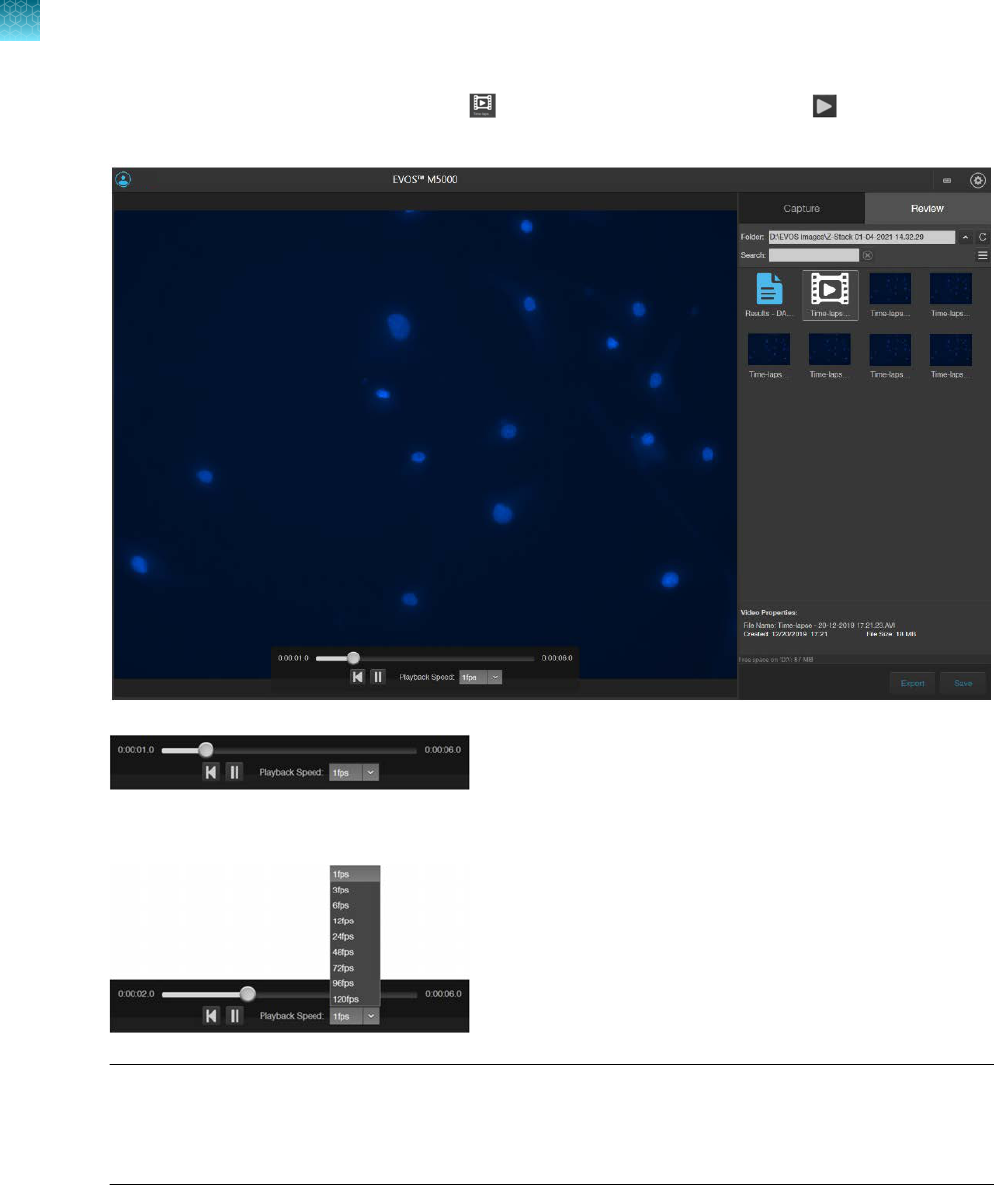
3.
To play the time-lapse movie, select the (Time-lapse Video) file, then click (Play) on the
Time Lapse Video Player.
4.
To change the playback speed, select the desired speed from the Playback Speed
menu.
Note: Playback Speed is independent of the Frame Rate
, which specifies how many images are
captured per second during the time-lapse recording (step 19 on page68). You can view the saved
time lapse recording at dierent playback speeds ranging from 1 fps (frames per second) to 120
fps (step 3 on page72).
Chapter7Capture time lapse images
Run a time lapse routine
7
72
EVOS
™
M5000 Imaging System User Guide

5.
To review individual images captured during the time-lapse routine, select the desired image from
the Review tab. The viewing area displays the selected image and the Review tab shows the
Image Properties, and Time Lapse and Auto Focus Settings.
6.
To zoom in on the image, use the Zoom slider.
7.
To annotate captured images and perform cell count and confluence
measurements, use the
Display Settings and Analysis Tools as described in Chapter 5, “Measure, annotate, and analyze
captured images”.
Chapter7Capture time lapse images
Run a time lapse routine
7
EVOS
™
M5000 Imaging System User Guide
73

Capture Z-Stack
Z-Stack tool
The Z-Stack tool allows you to capture multiple images of a selected field at dierent focal planes
along the Z-axis and combine them to generate a final image with a greater depth of field than any of
the individual source images.
Capture Z-stack images
1.
On the Capture tab, click Automate, then select Z-Stack to open the Z-Stack tool.
2.
Select the
Channels for Z-Stack that you want to capture. You can select multiple channels. In
this example, the DAPI channel is selected.
3.
If not already on, click
Light to illuminate the sample, then adjust Brightness and Focus using the
corresponding sliders on the Capture tab.
The focus position you set in this step is the initial Current Z position.
4.
To accept the
Current Z as the In Focus position, click Set.
To change the In Focus position, move the Coarse and Fine focus sliders on the Capture tab to
focus on the sample, then click Set.
8
74
EVOS
™
M5000 Imaging System User Guide

5.
Move the focus sliders up from the Current Z position to the desired Top position (upper boundary
of the Z-Stack), then click Set for Top.
6.
Move the focus sliders down from the Current Z position to the desired Bottom position (lower
boundar
y of the Z-Stack), then click Set for Bottom.
Note:
You can click the
Z number button for the Top, In Focus, and Bottom positions to jump to
those positions along the Z-axis.
7.
Define
the Z-Stack parameters to determine the number of optical sections captured in the
Z-Stack image set:
•
Automatically compute Z-Stack Parameters: Select to calculate the number of images and
their Z-positions automatically based on the Z-Stack boundaries and the default Step Size.
•
Manually Set Step Size: Select to enter the Step Size (Z-distance in µm between focal
planes) in the text box. The system calculates the number and Z-positions of the images
based on your entry.
•
Manually Set Number of Images: Select to enter the Number of Images (Z-distance in µm
between focal planes) in the text box. The system calculates Step Size and the Z positions of
the images.
Note:
You can take up to 100 images (optical sections) for a Z-Stack.
8.
Click
Browse to open the Choose Save Folder dialog.
9.
Go to the destination folder for the Z Stack images, then click Select Folder.
10.
Select the
File Type: PNG or TIFF.
11.
Select
Generate Projection Image to generate a projection image.
When selected, the system uses the most in-focus pixels from images captured at dierent focal
planes to generate a composite in-focus image. Each image in the Z-Stack is also separately
saved.
When unselected, the system only saves the individual Z-Stack images.
12.
Click
Start to capture the Z-Stack image sets based on your specifications.
The system provides information about the progress of the Z Stack protocol.
13.
When the Z-Stack routine is completed, the Review tab opens to the files captured in the routine.
Chapter8Capture Z-Stack
Capture Z-stack images
8
EVOS
™
M5000 Imaging System User Guide
75

Stage View
Overview
Note: Stage View requires an updated stage manufactured in early 2024 for all new EVOS
™
M5000
systems. Prior EVOS
™
M5000 systems using a stage with separate X- and Y-axis control knobs will not
have access to the Stage View feature but can be updated to have all of the other software features
described in the this user guide.
Stage View provides a method for marking points of interest in your sample in multiple vessel types.
Stage View also shows a map of specific vessels to display the actual location in the well or area
you are viewing. Vessel maps have been created for 6 precision-mount spring-retention EVOS
™
vessel
holders.
•
Well plates in 6-, 12-, 24-, 48-, 96-, and 384-well formats (Non-OSI compatible) (Cat. No. AMEP-
VH022 and AMEP-VH061)
•
Well plates in 6-, 12-, 24-, 48-, 96-, and 384-well formats (OSI compatible) (Cat. No. AMEP-VH028
and AMEP-VH040
•
Standard glass slides (Non-OSI compatible) (Cat. No. AMEP-VH044)
•
35 mm Petri dishes (OSI compatible) (Cat. No. AMEP-VH110)
For optimally finding and marking pins, we recommend using an appropriate precision-mount spring-
retention EVOS vessel holder. However, any non-precision EVOS
™
vessel holder can work provided the
holder is consistently positioned with each use.
9
76
EVOS
™
M5000 Imaging System User Guide


Set Stage Origin
1.
Select the Stage View tab.
2.
Switch to a low-power objective (2x, 4x, or 10x). This allows for easier locating of the calibration
pinhole and ensur
es enough space for the objective beneath the stage for movement.
3.
Click
Next. This turns on the transmitted light and moves the Coarse focus slider to the bottom.
4.
Remove any vessel on the stage and move the stage toward you and to the right using the stage
knobs.
5.
Click
Next. The center point appears.
6.
Find the pinhole (white circle in image view) and position the center point within the hole. Below
shows the scr
een view as the pinhole is lined up with the center point.
Note: When the objective is in position under the far left corner of the vessel holder only a small
r
otation of the X and Y control knobs is needed to find and center the pinhole. From this corner
position the X-axis (outer knob) is rotated approximately 5 mm toward you and the Y-axis (inner
knob) is rotated approximately 9 mm away from you to see the pinhole.
Chapter9Stage View
Set Stage Origin
9
78
EVOS
™
M5000 Imaging System User Guide

7.
Click Set Origin. The stage is now initialized for tracking its position.
8.
Click
Vessel to select a vessel type:
•
Well Plates
•
Slide or Dish
•
Blank Map
•
Load Pins
9.
Click the plate size or vessel size/type or load a pin map from the
Load Pin Map window:
•
Well Plates: 6, 12, 24, 48, 96, or 384 wells
•
Slide or Dish: 25 x 75 mm slide or 35 mm Petri dish
•
Blank Map: For all other vessels, such as a
T-flask, large Petri dish, and so on
Chapter9Stage View
Set Stage Origin
9
EVOS
™
M5000 Imaging System User Guide
79

•
Load Pins: Loads a previous map with pins and the appropriate vessel. Click Load Pins....
Click the desired Map Name row. Click Load. The Find Target window will open. Click Done
to return to the main screen.
Note: When selecting a well plate, any captured images will automatically add the well lD to
the individual saved filename.
10.
Click
Continue to load the vessel map. A representation of the vessel layout will appear in blue in
the Stage View tab. Also visible is an amber moveable crosshairs that tracks the stage position as
the stage is moved.
11.
Insert the vessel into the holder.
Carefully seat the vessel tightly into the corner opposite the
spring clip and ensure the spring clip correctly secures the vessel. For plates, the Current Well
will display A1 and update the well ID as the stage is moved to dierent wells (other vessel types
will not have the Current Well display). You can now move the amber crosshairs around the small
vessel map by moving the stage.
Chapter9Stage View
Set Stage Origin
9
80
EVOS
™
M5000 Imaging System User Guide

Mark pin locations
1.
Find a point of interest by moving the stage using the knobs.
2.
Once on a desired spot, click (Add pin). This will be Pin 1 or can be custom named by clicking
in the
field next to the
icon. Subsequent pins will be Pin 2, Pin 3, and so on, unless custom
named pr
eviously.
3.
Mark any other points of interest in the vessel by moving the stage, then clicking to add each
pin.
4.
Once all of the desired pins are created, click Find. The large Find Target map will appear showing
a more detailed view of marked pin locations in the vessel.
Find pins using the Find Target screen
The Find Target screen is an expanded view of the small vessel map.
Chapter9Stage View
Mark pin locations
9
EVOS
™
M5000 Imaging System User Guide
81

1.
Select a target by clicking on the desired pin or the pin name in the list. The pin will change color
from blue to amber and Target will update with the name of the selected pin.
2.
To
find the exact location of the current target (amber), move the stage using the knobs to move
the crosshairs. As the crosshairs move towards the target pin, the ΔX and ΔY values will change.
When the stage is close to the target pin, the crosshairs turn green.The pin is exactly located when
the values of ΔX and ΔY equal zero.
3.
Click
Done to close the Find Target screen, then turn on the illumination and check to verify that
the desired target is visible.
4.
(Optional)
Before closing Find Target, click Save to go to the Save Pin Map window. If needed,
enter a Map Name. Click Save.
The Save window also displays the following information:
•
Vessel Type
•
Number of Pins
•
Date Created
Chapter9Stage View
Find pins using the Find Target screen
9
82
EVOS
™
M5000 Imaging System User Guide

5.
(Optional) Each pin name in the Find Target window can be modified or deleted by hovering the
mouse over the pin name, then clicking (Edit) or (Delete). Click to complete the edit.
All pins can be deleted by clicking Clear all above the pin list.
6.
To use a previous map, click
Load. This opens the Load Pin Map window (see “Load Pin Map” on
page84).
This window allows for searching and editing of saved maps. Saved maps can be selected from
the list, using
Search, or sorting by vessel type, map name, or date modified.
Chapter9Stage View
Find pins using the Find Target screen
9
EVOS
™
M5000 Imaging System User Guide
83

Load Pin Map
•
To use a previous map, select a row, then click Load.
–
This window also allows for searching and editing saved maps. Saved maps can be selected
from the current list by using the Search function or sorting by vessel type.
–
Map names can be changed by clicking (Edit) or (Delete). Click to complete the edit.
Update the target pin location
If the target has shifted in the field of view relative to the pin (for example, your cell of interest has
migrated over time), you can update the pin's position to correct it. After clicking Done to dismiss the
Find Target window and verifying that the target has shifted relative to the pin, do the following:
1.
Re-center the target using the stage knobs in live observation mode (that is, with the light on).
2.
Open
Find Target.
3.
Select the pin to correct. By default, the
first pin is selected when opening the window, so you will
likely need to re-select the pin to be adjusted.
4.
Click
Update within the Target ΔX/ΔY area to move the pin to the current stage location
A window will display asking for confirmation you are moving the correct pin. Click Confirm.
Chapter9Stage View
Load Pin Map
9
84
EVOS
™
M5000 Imaging System User Guide

Review and analyze saved images
The Review tab allows you to review, annotate, and analyze still images, including those captured in
Time Lapse routines and Z-Stacks. You can also re-save or delete saved files.
•
Review saved images (“Review images”
on page86)
•
Configure display settings (“Configure display settings” on page88)
–
Adjust image display settings (“Adjust display settings for saved images” on page88)
–
Display grid (“Display grid” on page89)
–
Display scale bar (“Display scale bar” on page89)
•
View pixel intensity histogram (“View pixel intensity histogram” on page89)
•
Add measurements and annotations to saved images (“Add measurements and annotations to
saved images” on page90)
•
Analyze cell culture using saved images (“Analyze cell culture using saved images” on page90):
–
Perform Auto Count (Auto Count on page91)
–
Perform Manual Count (Manual Count on page91)
–
Measure confluence (Confluence on page91)
–
Calculate transfection eciency (Transfection Eciency on page91)
•
Save analysis results (“Save analysis results” on page92)
•
Perform batch analysis of saved images (“Save analysis results” on page92)
Note:
For a detailed description of the Review tab controls, see Appendix B, “Graphical user interface
(GUI)”
(“Review tab” on page126).
10
EVOS
™
M5000 Imaging System User Guide
85

Note: You can also view and analyze captured images that are saved to your Connect account with the
EVOS
™
Image Analysis application.
For more information on the EVOS
™
Image Analysis application, see Appendix C, “System overview”.
Review images
Review images
1.
Click the Review tab.
2.
In the
Folders panel, navigate to the folder containing your saved images, then click to select it.
The folder/image preview area displays thumbnail images for all viewable files in the selected
directory (the top-level USB directory is selected by default). If there are no viewable files in the
directory, the preview area will be empty.
3.
To change the layout of the saved images or to sort the saved images by name, file type, or date
cr
eated, click
(Display Settings) to expand the
Display Settings controls.
4.
To display the folder/image preview in list format, click
(List view)
.
5.
To display the folder/image preview in grid format, click
(Grid view)
.
Chapter10Review and analyze saved images
Review images
10
86
EVOS
™
M5000 Imaging System User Guide

6.
Click the image to select. The selected image is indicated with a box around it and the viewing
area displays the selected image.
The
Image Properties panel shows the metadata associated with the selected image.
Chapter10Review and analyze saved images
Review images
10
EVOS
™
M5000 Imaging System User Guide
87

Configure display settings
Adjust display settings for saved images
Display settings and analysis tools allow you to change image display settings, and to analyze and
annotate captured images.
Hover the pointer over the Viewing area to reveal the buttons for Display Settings and Analysis Tools.
Note: Display Settings
are available in both the Capture and the Review tabs and function the same
way.
•
Click (Image Display Settings) to expand the controls for image display parameters
(brightness, contr
ast, gamma). For detailed instructions, see “Adjust image display settings” on
page37.
Note:
The controls for image display settings are available only for captured channels. In the
e
xample below, the controls are available only for the DAPI, GFP, and Tx Red channels.
Chapter10Review and analyze saved images
Configure display settings
10
88
EVOS
™
M5000 Imaging System User Guide

Display grid
•
Click (Grid) to superimpose a grid over the Viewing area. For instructions on how to change
the Grid settings, see “Display grid” on page38.
Display scale bar
•
Click (Scale Bar) to superimpose a scale bar over the Viewing area. For instructions on how to
change scale bar settings, see “Display scale bar” on page39.
View pixel intensity histogram
Display histogram
1.
Hover the pointer over the Viewing area to reveal the buttons for Display Settings and Analysis
Tools.
2.
Click (Histogram) to open the Intensity Histogram plot.
The Pixel Intensity histogram shows the Pixel count vs. Intensity data of the image displayed in the
V
iewing area as well as the minimum, mean, and maximum pixel intensities. See “Align channels”
on page40 for more information on the Histogram tool.
Chapter10Review and analyze saved images
View pixel intensity histogram
10
EVOS
™
M5000 Imaging System User Guide
89

Note: The Histogram tool is available in both the Capture and the Review tabs and functions the
same way.
Add measurements and annotations to saved images
1.
Hover the pointer over the Viewing area to reveal the buttons for Display Settings and Analysis
Tools at the bottom of the screen.
2.
Click (Measurement and Annotations) to open the measurement and annotations tools.
For instructions on how to add and show measurements and annotations to your images, see “Add
measurements and annotations” on page42.
Note: Measurement and Annotations tools are available in both the
Capture and Review tabs
and functions the same way.
Analyze cell culture using saved images
1.
Hover the pointer over the Viewing area to reveal Display Settings and Analysis Tools, then click
123 (Show Cell Count) to display Auto Count, Manual Count, and Cell Culture options below
the Capture tab.
IMPORTANT! For analysis, only use 16-bit image files
(TIFF or PNG). The 16-bit images of
individual channels contain the full dynamic range and metadata needed for quantitative analysis,
whereas Display image files do not.
Chapter10Review and analyze saved images
Add measurements and annotations to saved images
10
90
EVOS
™
M5000 Imaging System User Guide

2.
Click to select from the following analysis options:
•
Auto Count: Automatically counts the objects displayed in the Viewing area based on your
specifications. With Auto Count, you can only count objects in a single fluorescence channel
(typically a nuclear stain channel).
For instructions on how to perform Auto Count, see “Count cells – auto count” on page45.
•
Manual Count: Allows you to tag objects in the Viewing area with up to six labels. As you
tag objects, the system keeps a running tally of the counts with percentages for each label
assigned. With Manual Count, you can count objects in multiple channels simultaneously.
For instructions on how to perform Manual Count, see “Count cells – manual count” on
page51.
•
Cell Culture: Allows you to measure the confluence of your culture and calculate the
transfection eciency.
–
Confluence: Allows you to select up to 5 reference objects for the target (i.e., cells) and
one background reference in your image, then automatically calculates the percentage
confluence of your culture.
For instructions on how to measure the confluence of your culture, see “Count cells –
manual count” on page51.
–
Transfection Eciency: Allows you to estimate the transfection eciency of your culture
by calculating the ratio of fluorescence area (i.e., cells expressing the fluorescence
marker) to the total cell area in your culture.
For instructions on how to calculate the transfection eciency, see “Calculate transfection
eciency” on page58.
3.
If desired, perform
Batch Analysis to the remainder of the images in the image folder (“Save
analysis results” on page92).
Note:
Batch Analysis allows you to save and apply the analysis parameters set in Auto Count,
Confluence, and Transfection
Eciency tools to other images that you have saved in an image
folder. Batch Analysis is not available for Manual Count.
Chapter10Review and analyze saved images
Analyze cell culture using saved images
10
EVOS
™
M5000 Imaging System User Guide
91

Save analysis results
Save
1.
When finished with the Auto Count, Manual Count, or Cell Culture analysis (Confluence and
Transfection Eciency), click Save to open the Save Composite Image dialog, then navigate to
the destination folder to save your count results.
2.
Enter the File name and select File type.
Chapter10Review and analyze saved images
Save analysis results
10
92
EVOS
™
M5000 Imaging System User Guide

3.
Select Save as screenshot to preserve a detailed account of your count results as an image.
When Save as screenshot is not selected, the software only saves the image as displayed in the
Viewing area. Table1 lists the various options available for saving analysis results.
Table1Save options for analysis tools.
Save Save as screenshot Save data
Auto Count
Image and object count;
counted objects and
user selected target and
background areas identified
Image (same as Save) and Auto
Count tab with object count,
histogram, and count options as
displayed in the Auto Count tool
Separate image
(same as Save)
and CSV files;
CSV file contains
brightness, area,
and circularity
data
Manual Count
Image and total object count;
object labels as tagged by
user during count
Image (same as Save) and Manual
Count tab with labels, object
counts, percentages, and total
count as displayed in the Manual
Count tool
Not applicable.
Confluence
Image in transmitted light
channel (with or without
mask) and %confluence;
user selected target and
background areas identified
Image (same as Save) and Cell
Culture Confluence tab with %
confluence and sensitivity as
displayed in the Confluence tool
Not applicable.
Transfection
Eciency
Image in selected channels
(with or without mask),
%confluence, and
% transfection eciency in
the fluorescence channel
Image (same as Save) and Cell
Culture Transfection Eciency tab
with %confluence, % transfection
eciency, threshold, and other
options as displayed in the
Transfection Eciency tool
Not applicable.
4.
If you have performed an
Auto Count, select Save data to save a CSV file of your count results
with individual object brightness, area, and circularity data.
This option is not available with Manual Count, Confluence measurement, or Transfection
Eciency calculation.
5.
Click
Save to save your analysis results.
Chapter10Review and analyze saved images
Save analysis results
10
EVOS
™
M5000 Imaging System User Guide
93

Batch analysis
Batch Analysis function
Batch Analysis allows you to save and apply the analysis parameters set in Auto Count, Confluence,
and Transfection Eciency tools to other images that you have collected and saved in an image
folder.
The Batch Analysis function is available as a Save Settings-Run Analysis split-button on the Auto
Count and Cell Culture panels on the Review tab. It is not available for Manual Count.
IMPORTANT! Images to be batch analyzed should all be of the same cell type and have the same
magnification
and illumination settings. For consistent measurements, do not mix dierent cell types,
magnifications, or illumination settings in the same folder when performing batch analysis.
IMPORTANT! For batch analysis, only use 16‑bit image
files (TIFF or PNG) that contain the full
dynamic range and metadata needed for quantitative analysis.
Save current analysis settings
1.
When
finished with Auto Count, Confluence measurement, or Transfection Eciency
calculation, click Batch, then select Save Settings.
2.
Enter the name for the settings, then click Save. The current analysis settings are saved for reuse,
which you can apply t
o other images that you have collected and saved an image folder.
Run batch analysis
1.
Navigate to the folder that contains the images you wish to analyze using the Batch Analysis tool,
then click on a representative image to open it.
2.
Perform Auto Count, Confluence measurement, or
Transfection Eciency calculation on the
open image as described previously.
3.
To analyze the remaining images in the same image folder, click Batch, then select Run Analysis.
Note:
You can also directly run Batch Analysis for images in an image folder using previously
saved Batch Analysis settings without first performing Auto Count, Confluence measurement, or
Transfection
Eciency calculation (see Step 4 on page95).
Chapter10Review and analyze saved images
Batch analysis
10
94
EVOS
™
M5000 Imaging System User Guide

4.
Select the Settings to use for Batch Analysis.
•
To use the current analysis settings (that is, analysis parameters that you have used in Step 2
on page94), select Current Settings.
•
To use previously saved analysis settings, select the desired option from the Select Settings
list. You can sort the list by fluorescence channel, date created, or last date used.
In this example, the previously saved U2OS Cell Count - DAPI setting is selected.
5.
To save the
Intensity, Area, and Circularity data of objects counted in Auto Count, select Object
Data. When Object Data is selected, the data is saved as separate CSV files for each analyzed
image in the analysis folder. The option to save Object Data is available only for Auto Count.
6.
To embed the measurements from the batch analysis in the images so that you can compare them
aft
er the analysis, select Annotated Images.
Note: Summary Data is always selected. After the analysis, summary data is included in the
analysis folder as a separate CSV file.
7.
To review the annotated images immediately after the analysis is complete, select Review
Annotated Images After Analysis.
8.
Click
Analyze to run batch analysis using the selected settings.
The software applies the analysis parameters used for the representative image to all the images in
the image folder.
When batch analysis is completed, the software saves the analysis results in a separate folder in
the same location as the analyzed images.
If Review Annotated Images After Analysis is selected, the software switches to the Review
mode and displays the list of analyzed images in the Review panel.
Note:
The analysis folder is named using the following format:
Batch <AnalysisDate><Unique Analysis ID>
For example, Batch 2021-03-02T112538
The images in the analysis folder retain their original name, but they are given the prefix AN_.
Chapter10Review and analyze saved images
Batch analysis
10
EVOS
™
M5000 Imaging System User Guide
95

Configure instrument settings
Overview
Settings tab
The Settings tab allows you to assign objectives to the objective turret, to calibrate objective
magnification, to set image and general instrument options, add and remove light cubes, and to
connect to a Wi-Fi network and to map network drives.
•
To open the settings tab, click (Settings).
•
To expand or collapse any of the controls, click the corresponding arrow ( or ).
11
96
EVOS
™
M5000 Imaging System User Guide

1
6
5
4
2
3
1
Objectives: Set up and calibrate objectives and assign objective profiles (“Adjust objective settings” on page98).
2
Display: Use White Balance Calibration and Hot Pixel Correction to adjust the white balance for the color camera
(“Calibrate white balance” on page100) and set saturated pixel options (“Set saturated pixel options” on page101).
3
General: Set general instrument options for focus wheel action, Capture All Channels, and Align Channels options
(“General settings” on page101).
4
Light Cubes: Add or remove EVOS
™
LED light cubes and assign pseudocolors for installed light cubes (“Change
EVOS
™
LED light cubes” on page109).
5
Network: Configure network settings (“Configure network settings” on page102).
6
Service
™
: Copy error logs, set date and time, and update software and firmware from the cloud or the USB flash
drive (“Service” on page105).
Chapter11Configure instrument settings
Overview
11
EVOS
™
M5000 Imaging System User Guide
97

Adjust objective settings
Assign objectives
After adding a new objective to the objective turret or replacing an older objective, assign the new
objective to the appropriate turret position. For instructions on how to remove an objective, see
“Change the objectives” on page110.
1.
Go to the Settings4Objectives tab.
2.
Find the newly installed objective in the Objectives list for the corresponding turret position.
3.
Click
Done.
IMPORTANT! For best results, calibrate the newly installed objective before using it in your
experiments (see
“Calibrate objective magnification” on page112.
Chapter11Configure instrument settings
Adjust objective settings
11
98
EVOS
™
M5000 Imaging System User Guide

Calibrate objective magnification
1.
Go to the Settings4Objectives, click (Actions) next to the newly installed objective, then
select Calibrate to launch the Objective Calibration tool.
2.
Mount the EVOS
™
Calibration Slide in the 2-slide vessel holder (Cat. No. AMEP-VH001) and select
the objective you want t
o calibrate by rotating the objective turret to the active position.
3.
Click
(Actions)
next to the active objective to select Calibrate.
4.
Follow the onscreen instructions to calibrate the objective
magnification for the selected objective.
For more information, see “Calibrate the objectives” on page112.
Delete objectives
After removing an objective from the objective turret, unassign the objective from the corresponding
turret position.
•
Go to Settings4Objectives, click
(Actions)
next to the turret position from which you have
removed the objective, then select Delete.
Chapter11Configure instrument settings
Adjust objective settings
11
EVOS
™
M5000 Imaging System User Guide
99

Calibrate white balance
Calibrate white balance
Calibrate White Balance calibrates color channel lighting.
1.
Go to Settings4Display tab, then click White Balance Calibration.
2.
Follow the screen instructions. Select a 20X or higher objective, then set the phase ring to
Brightfield
using the Phase ring selector (“Rear view” on page14).
3.
Remove any samples from the X-Y stage, then center the stage using the stage positioning knobs
(
“Rear view” on page14).
4.
Click
Start to begin the automatic white balance calibration procedure.
Chapter11Configure instrument settings
Calibrate white balance
11
100
EVOS
™
M5000 Imaging System User Guide

Set saturated pixel options
Highlight saturated pixels
Highlight saturated pixels function displays overexposed pixels on an image with the user-defined color,
which provides a visual aid for optimal illumination when adjusting the brightness settings.
1.
Go to Settings4Display, then click the Highlight Saturated Pixels checkbox.
2.
To assign a specific color to the saturated pixels in a channel, select the desired color from the
corr
esponding channel dropdown (Fluorescence, Transmitted, or RGB Transmitted).
Available colors for saturated pixels are Red, Green, Blue, and White.
General settings
General settings options
Define
Capture All checkbox behavior
By default, channel checkboxes stay checked after image capture when you select multiple channels
for simultaneous capture (see “Capture images in multiple channels” on page34).
Chapter11Configure instrument settings
Set saturated pixel options
11
EVOS
™
M5000 Imaging System User Guide
101

1.
To automatically unselect channel checkboxes after multichannel image capture, click Uncheck
Capture-All channels after Capture in the (Settings)4General tab.
2.
Click
Done.
Define Display Settings toolbar behavior
By default, the Display Settings and Analysis Tools toolbar is displayed automatically after image
capture and remains visible. You can change this behavior in the General settings.
1.
To automatically hide the Display Settings and Analysis Tools toolbar, click Auto-hide ‘Display
Settings and Analysis Tools’.
2.
Click Done
. The toolbar will be displayed when you hover the cursor over the Viewing area after
image capture. The toolbar will automatically hide if no action is taken.
Show Align Channels tool
By default, the button to display the Align Channels tool (indicated by the red arrow) is not shown in
the Display Settings and Analysis Tools toolbar. You can add the Align Channels tool to the toolbar in
the General settings.
1.
Select
Show Align Channels in ‘Display Settings and Analysis Tools’ in the Settings4General
tab.
2.
Click
Done. The Display Settings and Analysis Tools toolbar will display the Align Channels
button.
Note:
The controls for the
Align Channels tool are contextual. The tool only displays the controls
for the channels in which the selected multichannel fluorescent image has been captured.
Configure
network settings
You can connect the EVOS
™
M5000 Imaging System to a network via an Ethernet cable or Wi-Fi
adapt
or and save captured images directly to shared folders on the network. You can also connect to
your Connect
account, Connect-based platform, to store your image files and analyze them with the
EV
OS
™
Image Analysis application.
Chapter11Configure instrument settings
Configure network settings
11
102
EVOS
™
M5000 Imaging System User Guide

Connect to a Wi-Fi network
1.
Click (Settings).
2.
Click Network
.
3.
Click
Show Wi-Fi Networks, then select the network you want to join.
4.
Click
Close.
Map network drive
1.
Go to Settings4Network, then click Map Network Drive.
Chapter11Configure instrument settings
Configure network settings
11
EVOS
™
M5000 Imaging System User Guide
103

2.
Select the drive you want to map from the Drive menu.
3.
Click
Browse to open the Browse for Folder dialog.
4.
Navigate to the folder you want to map, then OK.
5.
If you want to reconnect to the selected drive and folder when you turn on the instrument, click
Reconnect at logon.
6.
If you want to reconnect as a dierent user, click Connect
using dierent credentials.
7.
To connect to a website for storing your documents and pictures, click the hyperlink, then navigate
t
o the desired website.
8.
After you have mapped the desired network drive and folder or connected to the website, click
Finish
.
Note:
When
Reconnect at logon is checked and a successful connection is established, the system
will attempt a reconnection to any previously connected networks or mapped drives every time the
instrument is turned on until you manually disconnect from the connected networks or mapped drives.
If no connection can be succesfully established to the previously mapped drive during start up, the
instrument displays the Reconnect to Mapped Network Drive dialog.
ABCDEF
\\A01file01\public
Chapter11Configure instrument settings
Configure network settings
11
104
EVOS
™
M5000 Imaging System User Guide

Service
The Service tab displays the current software and firmware versions of the system and allows you to
copy error logs, set date and time, and update software and firmware from the cloud or the USB flash
drive.
To view the Service tab, click (Settings), then select Service.
Copy error logs
•
On the
Service tab, click Copy Error Logs.
The instrument automatically saves a copy of the error logs in the previously mapped drive.
Set date and time
1.
On the
Service tab, click Set Date & Time.
2.
Enter the Date and
Time. For Time, select 24HR format or AM or PM for a 12-hour format.
3.
Click Done when finished.
Chapter11Configure instrument settings
Service
11
EVOS
™
M5000 Imaging System User Guide
105

Note: You cannot set the time more than 24hours in the past.
Update from cloud
1.
Restart your EVOS
™
M5000 instrument before an update to optimize the update process.
2.
To update the instrument software and
firmware from the Cloud, sign in to your Connect
account
(“Connect to the Thermo Fisher
™
Connect Platform” on page23).
3.
On the
Service tab, click Update from Cloud.
The instrument automatically searches your Connect
account, for the update.
4.
If a new update is available and the appropriate files are detected, the software pauses for a few
moments and then r
estarts.
5.
When a Windows
™
OS Setup dialog box opens, click Next
to proceed with the software update.
6.
The screen displays the update progress. When the update is complete, the system restarts and
the M5000 softwar
e automatically boots up again.
Update from USB
1.
Download the latest software from thermofisher.com/evos to a fresh USB flash drive with at least
200MB of available space.
2.
Restart your EVOS
™
M5000 instrument before an update to optimize the update process.
3.
Plug the USB
flash drive containing the newest software update into the EVOS
™
M5000instrument.
4.
On the
Service tab, click Update from USB.
5.
Locate the update
file from your USB Drive, then click Open.
6.
When a Windows
™
OS Setup dialog box opens, click
Next to proceed with the software update.
7.
The screen displays the update progress. When the update is complete, the system restarts and
the M5000 softwar
e automatically boots up again.
Chapter11Configure instrument settings
Service
11
106
EVOS
™
M5000 Imaging System User Guide

Instrument care and maintenance
General care
•
When cleaning optical elements, use only optical-grade materials to avoid scratching soft lens
coatings.
•
Use the appropriate cleaning solutions for each component, as indicated in the Decontamination
Procedures below.
•
If liquid spills on the instrument, turn o the power immediately and wipe dry.
•
Do not exchange objectives between instruments unless you know that the components have been
approved and recommended by Thermo Fisher Scientific.
•
After using, cover the instrument with the supplied dust cover.
Note: Always use the correct power supply. The power adaptor specifications appear on the serial
number label (above ports and plugs on the rear of the instrument) and in the Specifications. Damage
due to an incompatible power adaptor is not covered by warranty.
CAUTION! Never disassemble or service the instrument yourself. Do not remove any covers or parts
that require the use of a tool to obtain access to moving parts. Operators must be trained before
being allowed to perform the hazardous operation. Unauthorized repairs may damage the instrument
or alter its functionality, which may void your warranty. Contact your local EVOS
™
distributor to
arrange for service.
IMPORTANT! If you have any doubt about the compatibility of decontamination or cleaning agents
with parts of the equipment or with material contained in it, contact Technical Support or your local
EVOS
™
distributor for information.
12
EVOS
™
M5000 Imaging System User Guide
107

Objective lens care
Clean each objective periodically or when necessary with an optical-grade swab and a pre-moistened
lens wipe (or lens paper moistened with lens cleaning solution). To avoid scratching the soft lens
coatings, use only optical-grade cleaning materials and do not rub the lens.
Note: To protect all optical components of the instrument, use the dust cover when the instrument is
not in use.
Stage care
•
Clean the X-Y stage as needed with paper towels or Kimwipes
™
tissues dampened with 70%
ethanol.
•
When moving the EVOS
™
M5000 Imaging System, be sure to lock the X-Y stage using the Shipping
Restraint as shown in “Remove shipping restraints” on page18 to prevent the stage from sliding.
Decontamination procedures
In case hazardous material is spilt onto or into the components of the EVOS
™
M5000 Imaging System,
follow the decontamination procedure as described below.
1.
Turn power OFF.
2.
Clean the LCD display.
a.
Use a soft, dry, lint-free cloth to wipe o any dust from the screen.
b.
Clean the LCD display with a non-alcohol based cleaner made for flat-panel displays.
IMPORTANT! Do not spray cleaning
fluid directly onto the screen, as it may drip into the display.
3.
Lightly wipe working surfaces of the EVOS
™
M5000 Imaging System (stage top, objective turret,
housing, etc.) with paper t
owels or Kimwipes
™
tissues dampened with 70% ethanol or 4,000ppm
hydrogen peroxide (H
2
O
2
).
IMPORTANT! Do not allow decontamination solution to get into lubricated areas, such as the
stage roller bearings, or any points of rotation such as stage motors, condenser wheel, etc.
Do not soak any surface in decontamination solution.
NEVER spray liquid anywhere on the EVOS
™
M5000 Imaging System.
Always wipe surfaces with dampened paper towels instead.
Chapter12Instrument care and maintenance
Objective lens care
12
108
EVOS
™
M5000 Imaging System User Guide

Change EVOS
™
LED light cubes
To customize your EVOS
™
M5000 Imaging System, you can add and remove LED light cubes to fit the
instrument’s functionality to your own specific research needs. Each LED light cube is coded to allow
the imaging system to automatically recognize it in any position.
For a complete list of available light cubes and to inquire about custom light cubes, go to
thermofisher.com/evos or contact Technical Support.
WARNING! UV LIGHT HAZARD! The EVOS
™
M5000 Imaging System uses a Class 3B ultraviolet
LED for the DAPI channel.
Before changing the LED light cubes, ensure that the excitation light
is turned OFF (the instrument is not in Live mode).
Change LED light cube
1.
Select the position of the Light cube you want to change.
2.
Move the stage back to allow access to the light cube, which is centered under the back of the
stage.
3.
Use the light cube tool to loosen the two slotted screws (white arrows) that are flush with the
ridges on the light cube.
4.
Screw the threaded end of the light cube tool into the hole in the center of the light cube (yellow
arr
ow).
5.
Use the tool to tilt the light cube slightly toward you and lift out gently, and then remove tool from
cube.
Chapter12Instrument care and maintenance
Change EVOS
™
LED light cubes
12
EVOS
™
M5000 Imaging System User Guide
109

6.
Attach the tool to the new light cube and lower the cube into position so that the electronic
connection aligns properly (facing the back of the microscope) and the cube sits squarely in place
with the label facing toward the front.
7.
Unscrew the light cube tool from the cube, then use it to gently tighten the two slotted screws flush
with the ridges on the light cube.
Change the objectives
To customize your EVOS
™
M5000 Imaging System, you can add and remove objectives to fit the
instrument’
s functionality to your specific research needs.
Procedure for objective change
1.
Remove the objective you want to replace from the objective turret. You may need to move the
stage so that the objectives are accessible. Note the indicated position (1–5) of the removed
objective on the turret (red arrow).
Chapter12Instrument care and maintenance
Change the objectives
12
110
EVOS
™
M5000 Imaging System User Guide

2.
Screw the new objective into the open position in the objective turret. Note the part number of
the objective and the turret position. In this example, the new objective is installed into the turret
position 5.
3.
Go to the
Settings4Objectives tab, then find the objective in the Objectives list that matches the
newly installed objective.
Note: Calibrate the newly installed objective before use (“Calibrate the objectives” on page112).
Chapter12Instrument care and maintenance
Change the objectives
12
EVOS
™
M5000 Imaging System User Guide
111

Calibrate the objectives
Calibrate objective magnification allows the calibration of the field of view, parfocality, and
parcentration parameters of the selected objective. When calibrated, parfocality ensures that the
sample stays in focus when the objective is changed.
Note: The pre-installed objectives supplied with the EVOS
™
M5000 Imaging System have been pre-
calibrated. You do not need to calibrate them again unless they are reinstalled after removal from the
instrument.
Calibrate objective magnification
Calibration procedure requires the use of the EVOS
™
M5000 calibration slide (Cat. No. AMEP4720)
supplied with the EVOS
™
M5000 Imaging System. Total time required for objective calibration is
approximately 5 minutes.
Note: For best parfocality and parcentration, calibrate the installed objectives one after the other
without removing the calibration slide.
1.
Mount the EVOS
™
Calibration Slide face down in the slide vessel holder (you can use either of the
2 slots).
2.
Select the objective to calibrate using the Objective selection wheel (“Rear view” on page14).
3.
Go to
Settings4Objectives, click
(Action)
for the newly installed objective, then select
Calibrate to launch the Objective Calibration tool.
4.
Find a calibration circle that fits entirely in the field of view.
Chapter12Instrument care and maintenance
Calibrate the objectives
12
112
EVOS
™
M5000 Imaging System User Guide

5.
Focus on the calibration circle using the focus controls.
6.
Click and drag the green calibration lines to align them along the outer borders of the calibration
cir
cle.
7.
When
finished, click Save to complete the calibration. Repeat the calibration process for each
additional objective to be calibrated.
8.
When finished calibrating all installed objectives, click Done.
Chapter12Instrument care and maintenance
Calibrate the objectives
12
EVOS
™
M5000 Imaging System User Guide
113

Troubleshooting
Note: For additional technical support, contact your local EVOS
™
distributor. If you do not have your
distributor information, visit thermofisher.com/evos or contact Technical Support.
Image quality issues
Observation
Recommended action
Transmitted light image is too
dim (at higher magnifications)
Remove the condenser slider, if one is in place.
Specks, dots, or blurs on image Follow the instructions under “Objective lens care” (“Objective lens care”
on page108) to clean the objectives.
Uneven focus across screen
•
Position the sample so that it lies flat on the stage; ensure that the
sample’s thickness is even.
•
Ensure that the vessel holder is mounted flat with respect to the
stage.
Diculty focusing on
coverslipped sample on
standard slide
Place the slide so the coverslip is facing up (long working-distance
objectives require a thick optical substrate, and image best through 1.0–
1.5mm of glass or plastic).
Image display is black
•
Click a light button ( ) onscreen.
•
Center the sample over the objective.
•
Verify that the power supply is connected and the power switch is
on.
Image display is red, or red
patches cover parts of the
screen
•
Dim the illumination until the red highlights disappear to get the
maximum level of brightness without any overexposed areas.
•
Disable the Highlight Saturated Pixels option in the Settings tab.
A
114
EVOS
™
M5000 Imaging System User Guide

Stage view issues
Observation
Recommended actions
Cannot locate pinhole for
aligning the stage
Use a low-power objective (10x or less).
Cannot find original pin
locations on the vessel
Note the orientation of your slide or vessel in the vessel holder when
creating pins. Use the same orientation when re-locating pins.
Use a low-power objective (10x or less).
For microtiter plates, confirm plate is oriented with well A1 in the upper
left corner of the vessel holder.
Use Stage View-compliant vessel holders. These vessel holders have
screws in the corners and a spring clip to precisely align the vessel holder
on the stage and make re-locating pins easier. Additionally, the vessel
holders have index marks that align with the stagetop marks to confirm
the correct vessel holder orientation in case of removal and re-installation.
Pin map has substantially
shifted
Check the vessel position in the vessel holder to ensure it is placed tightly
in the reference corner.
Vessel was placed incorrectly before imaging and marking pins. Confirm
vessel and vessel holder were installed correctly before initial imaging and
pin placement.
Confirm the vessel holder thumbscrews are secured finger-tight to ensure
accurate alignment.
Software interface issues
Note: We recommend keeping the EVOS
™
M5000 Imaging System up to date with the latest software.
Observations Recommended actions
Image does not respond to
changes in focus or stage
position
Click Light to return to live observation.
Some of the software controls
are not available
The controls available on the EVOS
™
M5000 Imaging System are
contextual; only the controls relevant for the chosen task will be
available.
Save button does not respond
when clicked
Click Capture first; it is only possible to save an image that is captured.
AppendixATroubleshooting
Stage view issues
A
EVOS
™
M5000 Imaging System User Guide
115

(continued)
Observations Recommended actions
Unable to connect to network
•
Verify physical cable connections; confirm that the Ethernet jack is
active (for Ethernet connection).
•
Verify that the USB Wi-Fi adaptor for wireless network connection
is installed into one of the USB ports in the back (for wireless
connection).
•
Contact your network administrator to resolve any network issues.
Mechanical issues
Observations
Recommended actions
Filter cube axis does not move Remove the shipping restraint.
Vessel does not sit securely on moving stage Use the correct vessel holder for the application (visit
thermofisher.com/evos).
AppendixATroubleshooting
Mechanical issues
A
116
EVOS
™
M5000 Imaging System User Guide
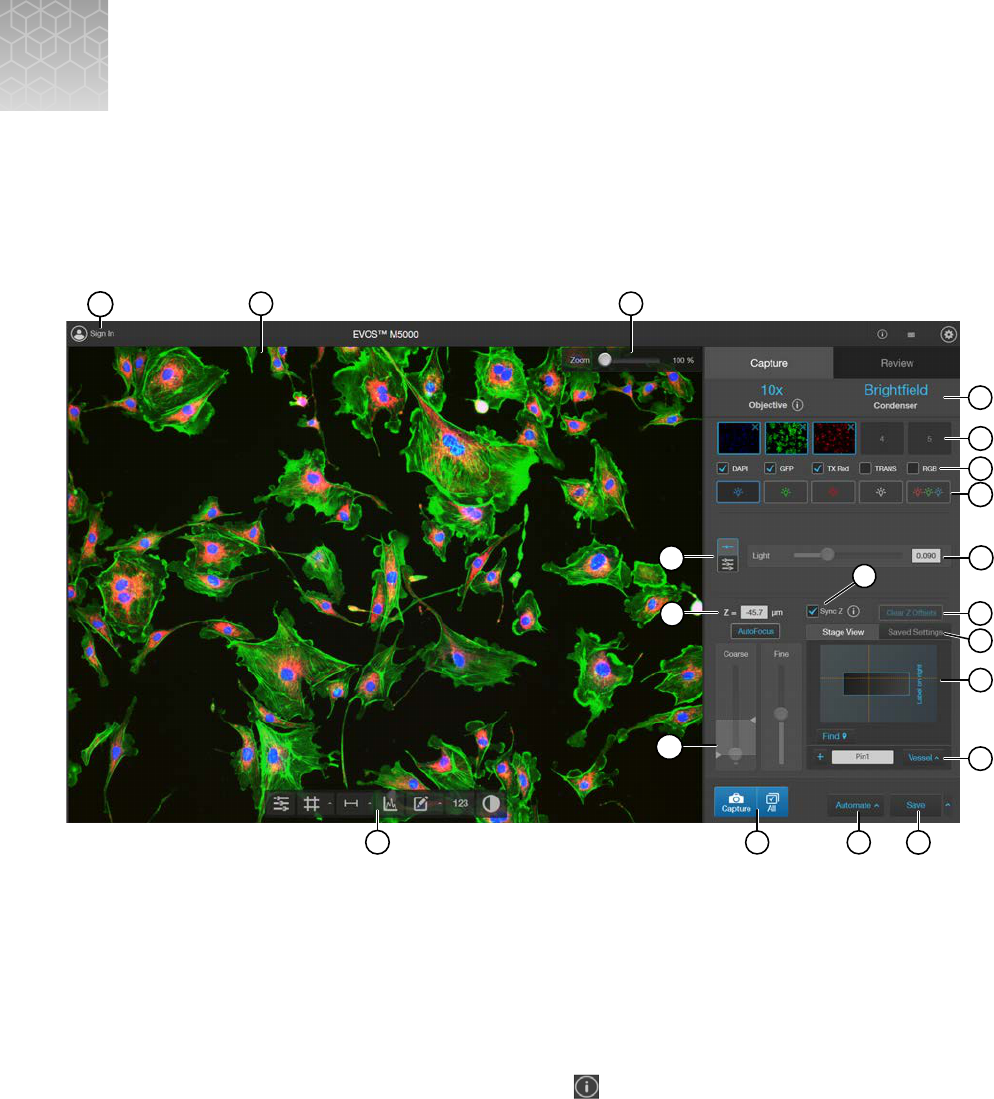
Graphical user interface (GUI)
Capture tab
15
9
12
13
14
4
7
5
6
20
17
18
16
3
11
1
2
8
19
10
1.
Sign In/User
: Allows you to sign in to and sign out of your Connect
account.
2.
Viewing area
: Displays live or captured images of the sample.
3.
Zoom slider: Zooms in and out of the Viewing area. The zoom range is 100% to 1000%.
4.
Active objective and phase ring: Displays the active objective and phase ring information.
•
If the selected objective and phase ring match, the selected phase ring is depicted in blue
font. If the objective and phase ring do not match, the phase ring is depicted in orange font.
•
To learn more about the current objective, click
.
5.
Thumbnails
: Display the most recently captured image stored in the memory buer for the
channel.
6.
Capture channels: Checkmarked channels to be captured using the All button.
B
EVOS
™
M5000 Imaging System User Guide
117

7.
Channel: Selects the light source from the installed LED light cubes (fluorescent channels) or from
the condenser (transmitted light). RGB Trans option outputs a color image from interlaced RGB
images in the Live mode.
•
Select a channel to turn on the excitation light and view in the Live mode. In Live mode, you
can use the brightness and focus controls.
•
Click the selected Channel button again to turn o the excitation light and exit the Live mode.
The current channel remains selected as indicated by the highlighted color around the channel
button.
8.
Brightness mode: Toggles between Simple and Advanced modes for brightness controls.
•
Simple mode allows you to control light intensity as a single Light parameter. The system will
automatically determine exposure and gain in order to minimize photobleaching.
•
Advanced mode allows you to adjust Light (that is, LED intensity), Exposure, and Gain
parameters individually.
9.
Brightness controls: Adjust the brightness for the selected channel using the simple or advanced
slider controls. The Exposure and Gain advanced sliders can help to optimize image details.
Simple slider control for Light adjustment. Advanced slider controls for Light, Exposure, and Gain
adjustments.
10.
Z = (µm)
: Displays the current focus position in µm along the Z-axis as controlled by the focus
knobs or focus sliders in the user interface. You can also change the Z-axis focus position by
entering the desired value into the Z = text box.
11.
Sync Z: Allows you to sync the Z-axis osets, which specify the optimal focus position for each
channel relative to the focus position in other channels.
•
When synched, movement of the Z-position in one channel changes the Z-position in all
channels, preserving their relative Z-positions.
•
When unsynched, adjusting the Z-position only aects the currently selected channel.
12.
Clear Z Osets: Clicking Clear Z Osets sets all of the channels to the same focal plane value
as the selected active channel. For example, if GFP is selected as the active channel and its focal
plane is -712, then clicking Clear Z Osets will set the other 3 channels with focal planes of -745,
-694, and -715 to be -712.
13.
Saved Settings: Allows you to save Z-axis focus positions and brightness settings for future use.
Click
to save the current settings.
14.
Stage View: Visual tool that allows precise marking of points of interest on various vessel types, as
well as the r
elocation of these points at a later time.
15.
Vessel type for Stage View: Allows selection of the vessel type being viewed. Vessel types
include, slides, petri dishes, and plates from 6 to 384 wells.
16.
Save (Quick Save, Auto Save): Saves the currently displayed image (all of the currently visible
channels) to the hard drive, USB drive, or network drive. After saving an image, the filename is
displayed in the upper-left corner of the screen.
17.
Automate: Allows you to display the controls for the Time Lapse and Z-Stack tools, and the
optional EVOS
™
Onstage Incubator.
AppendixBGraphical user interface (GUI)
Capture tab
B
118
EVOS
™
M5000 Imaging System User Guide

Time Lapse: Opens the Time Lapse tool, which allows you to create and run time lapse routines
to capture images at given intervals over a time period based on your specifications.
Z-Stack
: Opens the Z-Stack tool, which allows you to capture multiple images along the Z-axis
based on your specifications. You can use the images captured with the Z-Stack tool to generate a
Z-Stack Projection.
AppendixBGraphical user interface (GUI)
Capture tab
B
EVOS
™
M5000 Imaging System User Guide
119

Incubator
: Opens the Incubator Control, which allows you to control the optional EVOS
™
Onstage Incubator and monitor its status during your experiments.
Note: The Incubator Control window only appears if an EVOS
™
Onstage Incubator is connected to
the EV
OS
™
M5000 instrument.
18.
Capture
and All: Captures one channel (Capture) or multiple channels (All) using the current
capture settings and stores the image in the image cache of the channel in which it was captured.
AppendixBGraphical user interface (GUI)
Capture tab
B
120
EVOS
™
M5000 Imaging System User Guide

19.
Focus controls:
•
Autofocus: Runs autofocus in the selected channel.
Note: Do NOT use autofocus with oil-immersion objectives, as this can create air bubbles in
the oil or cause the objective to collide with the sample.
•
Coarse and Fine focus sliders: Allow you to adjust the focus in the selected channel when in
the Live mode.
Using the Autofocus Maximum and Autofocus Minimum controls (blue (when active)
triangles on the Coarse focus slider), you can limit autofocus to the selected region along
the Z-axis.
20.
Display Settings and Analysis Tools: Allow you to change image display settings in the Viewing
area, and analyze and annotate captured images.
(Image Display Settings)
: Opens the Image Display Settings tool, which allows you to adjust
image display parameters (
(Brightness)
,
(Contrast), and (Gamma Correction)) for the
select
ed channels.
(Align Channels)
: Allows you to correct pixel shifts that can occasionally appear when
performing multichannel fluorescence imaging at higher magnifications. The Align Channels tool
only displays the controls for the channels in which the selected multichannel fluorescent image
has been captured.
Note: The button to display the Align Channels tool is visible only if the Show Align Channels in
Display Settings and Analysis Tools
option is selected in the Settings4General tab.
(Display Grid/Grid Settings): Display Grid button switches the grid display in the Viewing
ar
ea on and o. Grid Settings allows you to set the grid size.
AppendixBGraphical user interface (GUI)
Capture tab
B
EVOS
™
M5000 Imaging System User Guide
121
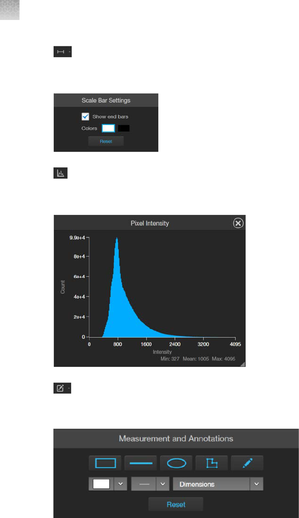
(Display Scale Bar/Scale Bar Settings): Display Scale Bar button switches the display of
the scale bar in the Viewing area on and o. Scale Bar Settings allows you to select scale bar
color and to display or hide end bars.
(Pixel Intensity)
: Opens the Pixel Intensity window, which displays the Pixel count vs.
Intensity histogram, where Intensity is linearly related to the number of photons detected by the
camera sensor.
Measurements and Annotations: Allows you to draw regions of interest (rectangle, ellipse,
polygon, line, or free-form) on the captured image and measure dimensions, area, or perimeter of
the drawn region.
AppendixBGraphical user interface (GUI)
Capture tab
B
122
EVOS
™
M5000 Imaging System User Guide

(Show Cell Count): Allows you to perform cell counts using the Auto Count or Manual Count
tools and to measure the confluence and transfection eciency of your culture from the captured
image using the Cell Culture tools.
•
Auto Count: Allows you to define auto count parameters by selecting representative target
objects, then count the objects by intensity, area, and circularity. See “Auto count controls” on
page128 for Auto Count controls.
AppendixBGraphical user interface (GUI)
Capture tab
B
EVOS
™
M5000 Imaging System User Guide
123
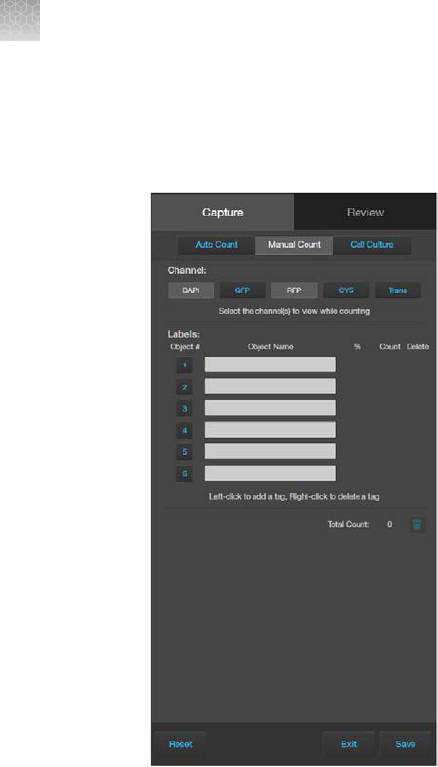
•
Manual Count: Allows you to manually mark items onscreen using up to 6 separate labels
and keep a running tally of the counts with percentages for each label. See “Manual count
controls” on page129 for Manual Count controls.
AppendixBGraphical user interface (GUI)
Capture tab
B
124
EVOS
™
M5000 Imaging System User Guide

•
Cell Culture: Allows you to measure the confluence of your culture and calculate the
transfection eciency. See “Cell culture – confluence controls” on page130 for Confluence
controls and “Cell culture – transfection eciency controls” on page131 for Transfection
Eciency controls.
(Toggle pseudocolor): Allows you to display images in pseudocolor or in grayscale in the
Viewing area. By default, color display is on.
AppendixBGraphical user interface (GUI)
Capture tab
B
EVOS
™
M5000 Imaging System User Guide
125

Review tab
5
6
7
8
15
2
16
1
4
17
14
13
12
9
10
11
3
1.
Sign In/User
: Allows you to sign in to and sign out of your Connect
account.
2.
Image file name
: File name of the image displayed in the Viewing area.
3.
Zoom slider: Zooms in and out of the image. The zoom range is 100% to 1000%.
4.
Keyboard Shortcuts: Instrument actions triggered by keyboard combinations instead of mouse
actions.
5.
Settings: Opens the Settings tab. See “Settings” on page132 for more information.
6.
Capture and Review tabs
: Allows you to toggle between the Capture and Review tabs.
7.
Up and Refresh
: Up button allows you go up one folder from the current folder. Refresh button
refreshes the list or grid of images in the current folder.
8.
Display Settings: Displays or hides the Layout controls.
9.
Folder: Displays the location of the current folder or image.
10.
Search
: Allows you to search images by file name in the selected folder.
11.
Layout: Allows you to toggle between grid or list view, increase or decrease the display size of the
folders or image files, and sort files by name, file type, or date created in ascending or descending
or
der.
AppendixBGraphical user interface (GUI)
Review tab
B
126
EVOS
™
M5000 Imaging System User Guide

12.
Image preview/Image list: Displays the preview or list of the image files and subfolders in the
current folder.
13.
Image Properties: Displays the metadata for the selected image file.
14.
Export
: Allows you to export the currently selected folder to a storage device.
15.
Save: Saves the currently opened image.
16.
Display settings and analysis tools: Allow you to change image display settings in the Viewing
ar
ea, and analyze and annotate captured images. See “Display settings and analysis tools” on
page36 for more information.
17.
Viewing area: Displays the selected image.
AppendixBGraphical user interface (GUI)
Review tab
B
EVOS
™
M5000 Imaging System User Guide
127

Auto count controls
6
7
1
2
3
4
5
8 9 10 11
1.
Analysis tools
: Allows you to toggle between Auto Count, Manual Count, or Cell Culture
(Confluence and Transfection Eciency) tools for image analysis.
2.
Select Target and Background
: Allows you to select representative target objects and
background areas for Auto Count.
3.
Split Cells
: Allows you to split multiple objects that have been counted as one into individual
objects based on shape or pixel intensity to increase the count accuracy.
4.
Refine: Selects intensity, area, or circularity by which to refine Auto Count results using the Count
Histogram.
5.
Count Histogram
: Allows you to set pixel intensity, area, or circularity thresholds to refine the Auto
Count results.
6.
Object Count
: Displays the object count based on the Auto Count parameters.
7.
Object color: Selects the color by which the counted objects are identified.
8.
Reset
: Resets the count to 0 and clears the selected targets and background areas.
9.
Batch Analysis
: Allows you to save and apply the analysis parameters to other images that
you have collected and saved in an image folder (see “Batch analysis” on page94 for more
information).
AppendixBGraphical user interface (GUI)
Auto count controls
B
128
EVOS
™
M5000 Imaging System User Guide

10.
Exit: Exits the Auto Count tool and displays the Review tab.
11.
Save: Saves the analysis results as an image in the selected file
format (see “Save analysis results”
on page92 for more information).
Manual count controls
7 8 9 10
3
4
5
1
2
6
1.
Analysis tools
: Allows you to toggle between Auto Count, Manual Count, or Cell Culture
(Confluence and Transfection Eciency) tools for image analysis.
2.
Object # and Object Name: Allows you to select the label (Object #) with which to tag objects in
the V
iewing area. Left-click on the objects in the Viewing area to tag them with the selected label;
right-click to delete a tag. In this example, Object #2 is selected. You can switch labels as desired.
See “Count cells – manual count” on page51 for more information. Object Name allows you to
assign a name for the Object #.
3.
% and Count: Displays the label count and its percentage of the total object count (total count of
all labels).
4.
Delete: Selects a label for deletion.
5.
Trash: Deletes the tags for the label and resets the label count to 0.
6.
Total Count: Displays the total count of objects tagged with all labels.
7.
Reset
: Resets all label counts and the total count to 0 and clears the Viewing area of all tags.
AppendixBGraphical user interface (GUI)
Manual count controls
B
EVOS
™
M5000 Imaging System User Guide
129

8.
Batch Analysis: Allows you to save and apply the analysis parameters to other images that
you have collected and saved in an image folder (see “Batch analysis” on page94 for more
information).
9.
Exit: Exits the Manual Count tool and displays the Review tab.
10.
Save: Saves the analysis results as an image in the selected
file format (see “Save analysis results”
on page92 for more information).
Cell culture – confluence controls
6
10
11 12
7
8
9
2
1
3
4
5
1.
Analysis tools
: Allows you to toggle between Auto Count, Manual Count, or Cell Culture
(Confluence and Transfection Eciency) tools for image analysis.
2.
Confluence
: Expands or hides the controls for the Confluence tool.
3.
Select Target and Background: Allows you to select representative cell and background areas for
the confluence
measurement.
4.
Sensitivity: Adjusts the algorithm sensitivity to pixel intensity (higher intensity = more pixels
included). Decr
easing the sensitivity reduces the confluence value.
5.
Show Mask: Indicates the areas included in the confluence
measurement.
6.
Mask Color: Selects the mask color.
AppendixBGraphical user interface (GUI)
Cell culture – confluence controls
B
130
EVOS
™
M5000 Imaging System User Guide

7.
Transfection Eciency: Expands or hides the controls for the Transfection Eciency tool. The
Transfection Eciency tool is inactive until the confluence measurement is completed.
8.
%
Confluence: Displays the percentage of the area covered by cells in the image, based on the
selected target and background areas and sensitivity.
9.
Reset: Resets the
Confluence and Transfection Eciency measurements to 0 and clears the
selected targets and background areas.
10.
Batch Analysis
: Allows you to save and apply the cell culture analysis parameters to other images
that you have collected and saved in an image folder (see “Batch analysis” on page94).
11.
Exit: Exits the Cell Culture
tool and displays the Review tab.
12.
Save
: Saves the analysis results as an image in the selected file format (see “Save analysis results”
on page92).
Cell culture – transfection eciency controls
7
8
9
10
11
12
13
2
1
3
4
5
6
1.
Analysis tools
: Allows you to toggle between Auto Count, Manual Count, or Cell Culture
(Confluence and Transfection Eciency) tools for image analysis.
2.
Confluence
: Expands or hides the controls for the Confluence tool.
3.
Transfection Eciency: Expands or hides the controls for the Transfection Eciency
tool.
4.
Fluorescence Channel selection: Selects the
fluorescence channel for transfection eciency
calculation.
AppendixBGraphical user interface (GUI)
Cell culture – transfection eciency controls
B
EVOS
™
M5000 Imaging System User Guide
131

5.
Fluorescence Channel: Toggles the display of the fluorescence channel.
6.
Transmitted Light Channel
: Toggles the display of the transmitted light.
7.
Threshold
: Adjusts the fluorescence threshold value. Only the cells that express above the set
threshold are used in the tranfection eciency calculation.
8.
Threshold Mask
: Indicates the areas above the set threshold value and are included in the
transfection eciency calculation.
9.
% Confluence
and %Transfection Eciency: Displays the calculated confluence and
transfection eciency values.
10.
Reset: Resets the
Confluence and Transfection Eciency measurements to 0 and clears the
selected targets and background areas.
11.
Exit: Exits the Cell Culture tool and displays the Review tab.
12.
Save
: Saves the analysis results as an image in the selected file format (see “Save analysis results”
on page92).
13.
Mask Color: Selects the threshold mask color.
Settings
7 8
4
5
2
3
6
1
AppendixBGraphical user interface (GUI)
Settings
B
132
EVOS
™
M5000 Imaging System User Guide

1.
Objectives: Allows you to assign and unassign objectives on the objective turret, and to calibrate
objective magnification.
2.
Display
: Allows you to calibrate color channel lighting (White Balance Calibration) and to assign
saturated pixel colors in the Fluorescence, Transmitted, and RGB Transmitted channels.
3.
General
: Allows you to define general instrument options such as save options for TIFF files, focus
wheel action, Saved Settings, Capture All Channels, and Align Channels options, and to clear
cached settings.
4.
Light Cubes
: Allows you to add or remove EVOS
™
LED light cubes from the instrument and to
assign pseudocolors t
o specific channels.
AppendixBGraphical user interface (GUI)
Settings
B
EVOS
™
M5000 Imaging System User Guide
133

5.
Network: Allows you to connect to a Wi-Fi network and to map network drives.
6.
Service: Displays the EVOS
™
M5000 hardware and software information, allows you to update
the EV
OS
™
M5000
firmware and software from Connect
, Connect-based platform, or using a USB
flash drive, and to copy the error logs.
7.
Done: Closes the Settings tabs and returns to the Capture tab.
AppendixBGraphical user interface (GUI)
Settings
B
134
EVOS
™
M5000 Imaging System User Guide

System overview
Technical specifications
Note: Technical specifications of the EVOS
™
M5000 Imaging System are subject to change without
notice. For the latest product information, see the product page (thermofisher.com/evos).
Physical characteristics
Dimensions (W × H × D): 46 × 59 × 46cm (18 × 23 × 18in)
Weight: 16kg (35lbs.)
Footprint: Approximately 92cm × 92cm (36in × 36in)
Operating temperature: 4°–32°C (40°–90°F)
Operating humidity: <90%, non-condensing
Operating power: 100–240 VAC, 1.8A
Frequency: 50–60Hz
Electrical input: 12VDC, 5A
Hardware
Optics: Infinity-corrected optical system; RMS-threaded objectives with 45 mm parfocal distance.
Illumination: Adjustable intensity LED (>50,000‑hour life per light cube).
Light cubes (not included): 4-position chamber for 4 fluorescence cubes plus brightfield. Wide
selection of standard and specialty light cubes (see “LED light cubes” on page136).
Contrast methods: Fluorescence and transmitted light (brightfield & phase contrast).
Objective turret: 5‑position; front-mounted control.
Objectives (not included): Wide selection of high-quality LWD and coverslip-corrected objectives.
Condenser: 60‑mm long working distance condenser, 4 position turret with one clear aperture and
3phaserings.
Stage: Manual X-Y position-sensing stage. Travel range of 120 mm × 80 mm, drop-in inserts to receive
vessel holders and lock down holders to fix the sample in place.
Focus mechanism: Automated focus mechanism with sub-micron resolution.
LCD display: 18.5‑inch high-resolution LCD display (1920 × 1080 pixel resolution)
Camera: High-sensitivity monochrome CMOS camera (2048 × 1536 pixels, 3.2 Megapixels) with
3.45 µm pixels.
C
EVOS
™
M5000 Imaging System User Guide
135

Captured images: 16‑bit monochrome (12‑bit dynamic range) TIFF or PNG; 8‑bit per RGB channel
TIFF, PNG, or JPG.
Output ports: 4‑pin power input port (12VDC, 5A), 2 USB 3.0, 2 USB 2.0
Networking capability: Connection through Windows
™
/SMB network via an Ethernet cable connection
or wirelessly using the supplied Wi-Fi adaptor.
Power supply: AC adaptor with country-specific power cords.
Operation principles and technical overview
LED illumination
The EVOS
™
M5000 Imaging System uses an adjustable-intensity LED light source provided by the
proprietary, user-interchangeable LED light cube (see below). The LED light source is as close as
possible to the objective and the number of optical elements is minimized. High-intensity illumination
over a short light path increases the eciency of fluorophore excitation, providing better detection of
weak fluorescent signals.
In contrast to traditional fluorescence microscopy light sources that use mercury, a toxic carcinogen
requiring special handling and disposal, the LED light source of the EVOS
™
M5000 Imaging System is
more environmentally friendly, energy ecient, and has a significantly longer life span (>50,000hours
versus 300 hours for a typical mercury bulb and 1,500hours for a metal halide bulb).
LED light cubes
Each user-interchangable, auto-configured light cube contains an LED, collimating optics, and filters.
In addition to the channel dedicated to the transmitted light from the condenser for brightfield contrast
applications, the EVOS
™
M5000 Imaging System can accommodate up to four fluorescent or specialty
light cubes for multi-fluorescence research applications.
The table below lists some of the common fluorescence and specialty light cubes available from
Thermo Fisher Scientific. For a complete list of available light cubes and to inquire about custom light
cubes, go to thermofisher.com/evos or contact Technical Support.
Light cube Dye
DAPI DAPI, Hoechst
™
, BFP
TagBFP TagBFP
CFP ECFP, Lucifer Yellow, Evans Blue
GFP GFP, Alexa Fluor
™
488, SYBR
™
Green, FITC
YFP EYFP, acridine orange + DNA
RFP RFP, Alexa Fluor
™
546, Alexa Fluor
™
555, Alexa Fluor
™
568, Cy
™
3, MitoTracker
™
Orange, RhodamineRed
™
, DsRed
Texas Red
™
Texas Red
™
, Alexa Fluor
™
568, Alexa Fluor
™
594, MitoTracker
™
Red, mCherry,
Cy
™
3.5
AppendixCSystem overview
Operation principles and technical overview
C
136
EVOS
™
M5000 Imaging System User Guide

(continued)
Light cube Dye
Cy5
™
Cy
™
5, Alexa Fluor
™
647, Alexa Fluor
™
660, DRAQ5
™
Cy
™
5.5 Cy
™
5.5, Alexa Fluor
™
660, Alexa Fluor
™
680, Alexa Fluor
™
700
Cy
™
7 Cy
™
7, IRDye
™
800CW
Specialty light cubes Dye
CFP-YFP em CFP/YFP (for FRET applications)
AO Acridine orange + RNA, simultaneous green/red with FL color
White Reflected light applications
AppendixCSystem overview
Operation principles and technical overview
C
EVOS
™
M5000 Imaging System User Guide
137

EVOS
™
image analysis
EVOS
™
image analysis
EVOS
™
Image Analysis is an easy to use online application for storing, viewing, and analyzing images
from your EVOS
™
M5000 Imaging System.
After you have signed in to your Connect account from the EVOS
™
M5000 Imaging System, you can
choose t
o save captured images directly to the application in addition to local storage.
You can then use the application for editing images (e.g., to adjust brightness and contrast,
annotations, pseudo coloring, etc.) as well as for
identification and quantification of cells.
The EVOS
™
Image Analysis application is available for free on the Connect platform. However,
you need a curr
ent Connect
account to sign in. To create your Connect account online, go to
thermofisher.com/connect.
Note: This sections provides an overview of the EVOS
™
Image Analysis application. For detailed
instructions on how t
o use the EVOS
™
Image Analysis application, refer to the EVOS
™
Image Analysis
Help System
. A PDF version of the EVOS
™
Image Analysis Help System (Pub. No. MAN0018314) is also
available for download at thermofisher.com.
D
138
EVOS
™
M5000 Imaging System User Guide

Gallery
The EVOS
™
Image Analysis Gallery contains the images saved from your EVOS
™
M5000 Imaging
System to your Connect account. You can view the images and image metadata in this tab and select
individual images for further image adjustment and analysis.
To adjust an image or to analyze it (that is, perform Auto Count and Manual Count), select the desired
image in the Gallery, then click Next to open the Edit Image screen (“Edit image” on page139).
Edit image
The
Edit Image screen contains the Adjust and Analyze tabs.
AppendixDEVOS
™
image analysis
Gallery
D
EVOS
™
M5000 Imaging System User Guide
139

Adjust tab
The Adjust tab allows you to zoom in to your selected image, adjust brightness and contrast values,
and add line measurements and annotations. The measurement and annotation functions of the EVOS
™
Image Analysis application are identical to the Analysis tools of the EVOS
™
M5000 Imaging System
(Chapter 5, “Measure, annotate, and analyze captured images”).
AppendixDEVOS
™
image analysis
Edit image
D
140
EVOS
™
M5000 Imaging System User Guide

Analyze tab
The Analyze tab allows you to use Auto Count and Manual Count. The Auto Count and Manual
Count functions of the EVOS
™
Image Analysis application are identical to the count tools of the EVOS
™
M5000 Imaging System (“Analyze cell culture” on page44).
AppendixDEVOS
™
image analysis
Edit image
D
EVOS
™
M5000 Imaging System User Guide
141

Glossary
Software controls and functions
•
Autofocus: The Autofocus button triggers the microscope to move through a Z-axis range
(defined by the triangle sliders in the Coarse focus control) and search for the optimal focal plane.
The display shows a live view as the objective sweeps through the defined Z-axis range. Autofocus
uses an image-based focusing algorithm to achieve the desired focus.
Note: Do NOT use autofocus with oil-immersion objectives, as this can create air bubbles in the oil
or cause the objective to collide with the sample.
•
Brightness, Contrast, and Gamma: The Image Display Settings panel provides slider controls
for adjusting the brightness, contrast, and gamma of the current image. These controls can be
used to darken or lighten the image and increase or decrease contrast. The Gamma slider allows
for non-linear contrast adjustments. Moving this slider to the left can help reduce undesired
background fluorescence, particularly in images with nonspecific background fluorescence.
Conversely, moving this slider to the right can enhance fluorescence signals and make them more
visible, especially in images with very faint signals, and can be particularly useful for detecting
signals at the lower limits of brightness.
•
Keyboard shortcuts: Keyboard shortcuts are helpful for eciently performing instrument functions
without relying on mouse actions. These shortcuts typically involve holding down the Control
key and pressing a designated key to trigger a specific action. Keyboard shortcuts for the
EVOS
™
M5000 instrument can be used for a range of tasks, including selecting the illumination
channel, toggling the current channel on and o, running autofocus, capturing the current channel,
capturing all selected channels, and saving the displayed image using the current Save settings.
By familiarizing yourself with these shortcuts you can streamline your workflow and enhance
productivity while operating the instrument.
•
Simple and Advanced illumination controls: Simple illumination operates with one slider using
an intelligent algorithm to adjust the LED brightness, exposure time, and camera gain at the
same time. Advanced illumination allows control of the same parameters using 3 separate sliders.
Clicking the icon with 3 sliders from the default Simple illumination control (1 slider) switches to the
Advanced option.
Note: The Simple illumination single slider uses an intelligent algorithm designed to maximize the
signal-to-noise ratio and minimize photobleaching. For most imaging work we recommend using
the single slider to adjust the illumination. For more advanced users it may be useful to control
these settings individually, but please note it is also possible to photobleach the sample or degrade
images if you use the wrong combination of settings.
E
142
EVOS
™
M5000 Imaging System User Guide

•
Sync Z: The Sync Z feature is designed to enable the user to focus on a single channel while the
other channels are adjusted automatically. This is accomplished by first adjusting the focus of each
channel individually with the Sync Z feature unchecked. This will establish unique osets for each
channel. Once this initial adjustment is complete, the Sync Z feature can be enabled and thereafter
focusing on one channel will automatically adjust the focus of the others using the same osets
that were established during the individual setup. If at any point the osets become misaligned, the
Clear Z Osets button can be used to quickly reset and start again.
Image files
•
Channel: A channel refers to a specific illumination range used to capture images. Fluorescence
channels are defined by their excitation and emission wavelengths, which enable the detection of
dierent cell populations or subcellular structures. Transmitted light is full-spectrum and can be
used either alone or in conjunction with phase-contrast optics to provide images based on the light
that passes through the sample. The interaction of the light with the sample as it passes through
cells or tissue provides contrast for transmitted light images.
•
Channel overlay: When multiple channels are captured from a single location, they can be overlaid
in an image to visualize the relationships between dierent cells or structures identified by each
channel. The overlaid channels are pseudocolored, meaning that distinct colors are assigned to
each channel for better dierentiation. It is important to note that an image with overlaid channels is
intended for display purposes only and should not be used for quantitative analysis.
•
Analysis image: An analysis image refers to a single-channel image that is saved in a lossless
format using the full dynamic range of the camera (12 bits). These images are saved in 16-bit
format, which may require specialized viewing software for proper display. When viewed on other
software, analysis images are displayed in grayscale monochrome, representing the pure data
that was captured. To enhance visualization, the EVOS
™
software automatically displays analysis
images using the appropriate pseudocolor. It's important to note that the EVOS
™
software does not
modify analysis images in any way. This means that features like scalebars or annotations cannot
be added, and changing the contrast onscreen does not alter the underlying data in the image file.
•
Display image: A display image refers to a modified version of an original image that can be
used outside of the EVOS
™
M5000 software. These images are usually pseudocolored, either
representing a single channel or multiple overlaid channels, and are intended for purposes such as
PowerPoint
™
presentations or sharing with colleagues. It's important to note that display images
are saved in an 8-bits per channel file format, which may compromise the intensity information
and result in lower quality images for quantitative analysis. While display images can be useful
for manual tasks like cell counting or size/distance measurements, it is not recommended to
use them with analysis tools like Auto Count, Confluence, or Transfection Eciency, as these
measurements rely on the complete intensity information that might be lost in display images.
Display images can be customized with features like scale bars or annotations, and adjusted
brightness and contrast values for visual presentation; as such they are not the original data and
should not be used for analysis purposes.
AppendixEGlossary
Image files
E
EVOS
™
M5000 Imaging System User Guide
143

•
Pseudocolor image: A pseudocolor image is a modified version of a grayscale image that uses
a single color (for a fluorescence channel) or multiple distinct colors (for a fluorescence overlay
image) to represent the image as it would be seen through a microscope's oculars. The chosen
color(s) typically correspond to the emission wavelength of the fluorescence channel used to
capture the image. With the EVOS
™
M5000 instrument, which uses a highly sensitive monochrome
camera, all fluorescence images are initially captured as monochrome. These images can then be
saved as either monochrome 16-bit images for analysis or pseudocolored 8-bit images for display
purposes. It's important to note that any saved pseudocolor image is always considered to be a
display image.
•
TIFF image file: TIFF is an acronym for "tagged image file format", a common digital image file
encoding standard. "Tags" consist of information (also known as metadata) stored in the image
file along with the image. TIFF images for microscopy can contain tags about the objective,
illumination info, camera, exposure time, and other details of image capture. TIFF files are not
compressed and can be saved in analysis or display format. EVOS
™
TIFF files have the following
naming conventions:
–
Basefilename_quicksavenumber_channel_well.ti = 8-bit pseudocolor channel for display
–
Basefilename_quicksavenumber_channel_well.tif = 16-bit monochrome channel for analysis
–
Basefilename_quicksavenumber_well.tif = 8-bit, RGB multi-channel pseudocolor overlay for
display
Note: Bolded text in the file names indicates variables that change between the types.
•
PNG image file: PNG is an acronym for "portable network graphics", a common digital image
file encoding standard. Like TIFF files, PNG files contain information (known as "chunks") stored
along with the image. PNG images for microscopy can contain chunks (that is, metadata) about the
objective, illumination information, camera, exposure time, and other details of image capture. PNG
files use lossless compression and can be saved in analysis or display format. EVOS
™
PNG files
have the following naming conventions:
–
Basefilename_quicksavenumber_channel_well_D.PNG = 8-bit pseudocolor channel for
display
–
Basefilename_quicksavenumber_channel_well.png = 16-bit monochrome channel for analysis
–
Basefilename_quicksavenumber_well.png = 8-bit RGB multi-channel pseudocolor overlay for
display
Note: Bolded text in the file names indicates variables that change between the types.
•
JPEG image file: JPEG is an acronym for "joint photographics experts group", a common digital
image file encoding standard. As opposed to TIFF or PNG files, JPEG image files are often highly
compressed, which results in data loss. In addition to lossy compression, standard JPEG images
do not contain metadata and have limited dynamic range (only 8-bit images). These images are
useful for display, sharing, and viewing and can easily be shared and viewed, however, they are not
optimal for analysis. EVOS
™
JPEG files have the following naming conventions:
–
Basefilename_quicksavenumber_channel_well.jpg = 8-bit pseudocolor channel for display
–
Basefilename_quicksavenumber_well.jpg = 8-bit RGB multi-channel pseudocolor overlay for
display
Note: Bolded text in the file names indicates variables that change between the types.
AppendixEGlossary
Image files
E
144
EVOS
™
M5000 Imaging System User Guide

Microscope controls and optics
•
Light cube: A light cube is a proprietary optical module that can be easily installed by the user
in an EVOS
™
fluorescence microscope or fluorescence-capable Countess
™
cell counter. Each
light cube contains a high-power LED as well as the electronics and optical elements needed
to illuminate and capture a single fluorescence channel. Upon powering on the instrument, light
cubes are automatically detected and assigned in the control software, requiring no additional
configuration from the user. This design allows for easy integration and use, providing a simple and
ecient way to enhance fluorescence imaging capabilities.
•
Optical substrate: The optical substrate refers to the optical material (typically made of glass or
plastic) located between the objective and the sample in a microscope. The optical properties and
thickness of this material play a crucial role in determining image quality. Microscope objectives
are specifically designed to be used with a particular thickness of optical substrate. Using an
incorrect thickness or material can lead to issues such as diculties in focusing, excessive
background autofluorescence, or even the inability to focus on the cells. It is important to note
that oil-immersion objectives require specialized oil as part of the optical substrate, which must
have the correct refractive index for optimal imaging results.
•
Stage X axis: Movement of the stage in the horizontal direction using the X-axis stage control
knob.
•
Stage Y axis: Movement of the stage in the vertical direction (that is, away or toward the user)
using the Y-axis stage control knob.
•
Turret: A mechanical rotary control in the microscope that allows the user to move optical elements
into or out of the light path. An objective turret allows the selection of dierent magnifying
objectives, whereas a condenser turret allows use of various phase-contrast rings or an open
aperture for transmitted light illumination.
•
Vessel: A holder for a biological specimen made of glass or plastic, with optical properties suitable
for use with a microscope.
•
Vessel Holder: An accessory that mounts on the stage to hold a particular type of sample vessel
(for example, an opening for a microtiter plate, glass slide, or 35 mm Petri dish)
•
Z plane: The focal plane of the microscope. The Z plane position is controlled by the focus knobs,
the focus sliders in the user interface, or by running the Autofocus function.
AppendixEGlossary
Microscope controls and optics
E
EVOS
™
M5000 Imaging System User Guide
145

Stage View feature
•
Crosshairs: The crosshairs are a visual aid that provides real-time information about the position of
the objective lens relative to the stage. The crosshairs can be seen on both the small vessel map in
the Stage View tab and the larger vessel map in the Find Target window. When the crosshairs are
within 4 units of the target in both the X and Y directions in the Find Target window, they change
color from amber to green. This change indicates that the crosshairs are close enough to the target
to typically have it within the field of view.
•
Pin: A precise stage location created by the user which can be re-located in either the same
imaging session or a dierent imaging session.
•
Pinhole: A precise location on a Stage View vessel holder which is used to set the stage origin
after powering on the instrument.
•
Pin map: A collection of pins corresponding to multiple areas of interest on a biological sample (for
example, in dierent wells of a microtiter plate, various locations on a histology tissue slide, in a 35
mm Petri dish, etc.).
AppendixEGlossary
Stage View feature
E
146
EVOS
™
M5000 Imaging System User Guide

Safety
WARNING! GENERAL SAFETY. Using this product in a manner not specified in the user
documentation may result in personal injury or damage to the instrument or device. Ensure that
anyone using this product has received instructions in general safety practices for laboratories and
the safety information provided in this document.
·
Before using an instrument or device, read and understand the safety information provided in the
user documentation provided by the manufacturer of the instrument or device.
·
Before handling chemicals, read and understand all applicable Safety Data Sheets (SDSs) and use
appropriate personal protective equipment (gloves, gowns, eye protection, and so on). To obtain
SDSs, visit thermofisher.com/support.
Symbols on this instrument
Symbols may be found on the instrument to warn against potential hazards or convey important safety
information. In this document, the hazard symbol is used along with one of the following user attention
words.
•
CAUTION!—Indicates a potentially hazardous situation that, if not avoided, may result in minor or
moderate injury. It may also be used to alert against unsafe practices.
•
WARNING!—Indicates a potentially hazardous situation that, if not avoided, could result in death or
serious injury.
•
DANGER!—Indicates an imminently hazardous situation that, if not avoided, will result in death or
serious injury.
Standard safety symbols
Symbol and description
CAUTION! Risk of danger. Consult the manual for further safety information.
CAUTION! Risk of electrical shock.
CAUTION! Hot surface.
F
EVOS
™
M5000 Imaging System User Guide
147

(continued)
Symbol and description
CAUTION! Potential biohazard.
CAUTION! Ultraviolet light.
Symbole et description
MISE EN GARDE! Risque de danger. Consulter le manuel pour d’autres renseignements de
sécurité.
MISE EN GARDE! Risque de choc électrique.
MISE EN GARDE! Surface chaude.
MISE EN GARDE! Danger biologique potentiel.
MISE EN GARDE! Rayonnement ultraviolet.
AppendixFSafety
Symbols on this instrument
F
148
EVOS
™
M5000 Imaging System User Guide

Location of labels
Labels and location
3
2
1
Figure5
Instrument information labels (back panel)
1
Instrument information label
2
Technical support information
3
Instrument passwords label
Control and connection symbols
Symbols and descriptions
On (Power)
O
(Power)
Protective conductor terminal (main ground)
Alternating current
Conformity symbols
Conformity mark
Description
Indicates conformity with safety requirements for Canada and U.S.A.
Indicates conformity with China RoHS requirements.
AppendixFSafety
Symbols on this instrument
F
EVOS
™
M5000 Imaging System User Guide
149

(continued)
Conformity mark
Description
Indicates conformity with European Union requirements.
Indicates conformity with Australian standards for electromagnetic compatibility.
Indicates conformity with the WEEE Directive 2012/19/EU.
CAUTION! To minimize negative environmental impact from disposal of
electronic waste, do not dispose of electronic waste in unsorted municipal
waste. Follow local municipal waste ordinances for proper disposal provision
and contact customer service for information about responsible disposal
options.
Safety information for instruments not manufactured by
Thermo Fisher
Scientific
Some of the accessories provided as part of the instrument system are not designed or built by Thermo
Fisher
Scientific
. Consult the manufacturer's documentation for the information needed for the safe use
of these pr
oducts.
Instrument safety
General
CAUTION! Do not remove instrument protective covers. If you remove the protective instrument
panels or disable interlock devices, you may be exposed to serious hazards including, but not limited
to, severe electrical shock, laser exposure, crushing, or chemical exposure.
If covers are removed, do not use the instrument. Contact Technical Support.
CAUTION! Solvents and Pressurized fluids. Wear eye protection when working with any
pressurized
fluids. Use caution when working with any polymeric tubing that is under pressure:
·
Extinguish any nearby flames if you use flammable solvents.
·
Do not use polymeric tubing that has been severely stressed or kinked.
·
Do not use polymeric tubing with tetrahydrofuran or nitric and sulfuric acids.
·
Be aware that methylene chloride and dimethyl sulfoxide cause polymeric tubing to swell and
greatly reduce the rupture pressure of the tubing.
·
Be aware that high solvent flow rates (~40mL/min) may cause a static charge to build up on the
surface of the tubing and electrical sparks may result.
AppendixFSafety
Safety information for instruments not manufactured by Thermo Fisher Scientific
F
150
EVOS
™
M5000 Imaging System User Guide

Physical injury
CAUTION! Moving and Lifting Injury. Improper lifting can cause painful and permanent back injury.
Things to consider before lifting or moving the instrument or accessories:
·
Depending on the weight, moving or lifting may require two or more persons.
·
If you decide to lift or move the instrument after it has been installed, do not attempt to do so
without the assistance of others, the use of appropriate moving equipment, and proper lifting
techniques.
·
Ensure you have a secure, comfortable grip on the instrument or accessory.
·
Make sure that the path from where the object is to where it is being moved is clear of
obstructions.
·
Do not lift an object and twist your torso at the same time. Keep your spine in a good neutral
position while lifting with your legs.
·
Participants should coordinate lift and move intentions with each other before lifting and carrying.
·
For smaller packages, rather than lifting the object from the packing box, carefully tilt the box on its
side and hold it stationary while someone else slides the contents out of the box.
CAUTION! Moving Parts. Moving parts can crush, pinch and cut. Keep hands clear of moving parts
while operating the instrument. Disconnect power before servicing.
AppendixFSafety
Instrument safety
F
EVOS
™
M5000 Imaging System User Guide
151

Electrical safety
WARNING! Ensure appropriate electrical supply. For safe operation of the instrument:
·
Plug the system into a properly grounded receptacle with adequate current capacity.
·
Ensure the electrical supply is of suitable voltage.
·
Never operate the instrument with the ground disconnected. Grounding continuity is required for
safe operation of the instrument.
AVERTISSEMENT! Veiller à utiliser une alimentation électrique appropriée. Pour garantir le
fonctionnement de l’instrument en toute sécurité :
·
Brancher le système sur une prise électrique correctement mise à la terre et de puissance adéqua
t
e.
·
S’assurer que la tension électrique est convenable.
·
Ne jamais utiliser l’instrument alors que le dispositif de mise à la terre est déconnecté. La continui
té de la mise à la terre est impérative pour le fonctionnement de l’instrument en toute sécurité.
WARNING! Power Supply Line Cords. Use properly configured
and approved line cords for the
power supply in your facility. If the line cord is damaged, contact Technical Support.
AVERTISSEMENT! Cordons d’alimentation électrique. Utiliser des cordons d’alimentation adap
tés et approuvés pour raccorder l’instrument au circuit électrique du site.
WARNING! Disconnecting Power. To fully disconnect power either detach or unplug the power
cord, positioning the instrument such that the power cord is accessible.
AVERTISSEMENT! Déconnecter l’alimentation. Pour déconnecter entièrement l’alimentation, dé
tacher ou débrancher le cordon d’alimentation. Placer l’instrument de manière à ce que le cordon
d’alimentation soit accessible.
Overvoltage rating
The EVOS
™
M3000 Imaging System has an installation (overvoltage) category of II, and is classified as
portable equipment.
AppendixFSafety
Instrument safety
F
152
EVOS
™
M5000 Imaging System User Guide

Cleaning and decontamination
CAUTION! Cleaning and Decontamination. Use only the cleaning and decontamination methods
that are specified in the manufacturer user documentation. It is the responsibility of the operator (or
other responsible person) to ensure that the following requirements are met:
·
No decontamination or cleaning agents are used that can react with parts of the equipment or with
material that is contained in the equipment. Use of such agents could cause a HAZARD condition.
·
The instrument is properly decontaminated a) if hazardous material is spilled onto or into the
equipment, and/or b) before the instrument is serviced at your facility or is sent for repair,
maintenance, trade-in, disposal, or termination of a loan. Request decontamination forms from
customer service.
·
Before using any cleaning or decontamination methods (except methods that are recommended by
the manufacturer), confirm with the manufacturer that the proposed method will not damage the
equipment.
MISE EN GARDE! Nettoyage et décontamination.
Utiliser uniquement les méthodes de nettoya
ge et de décontamination indiquées dans la documentation du fabricant destinée aux utilisateurs.
L’opérateur (ou toute autre personne responsable) est tenu d’assurer le respect des exigences sui
vantes:
·
Ne pas utiliser d’agents de nettoyage ou de décontamination susceptibles de réagir avec certaines
parties de l’appareil ou avec les matières qu’il contient et de constituer, de ce fait, un DANGER.
·
L’instrument doit être correctement décontaminé a) si des substances dangereuses sont renver
sées sur ou à l’intérieur de l’équipement, et/ou b) avant de le faire réviser sur site ou de l’envoyer
à des fins de réparation, de maintenance, de revente, d’élimination ou à l’expiration d’une période
de prêt (des informations sur les formes de décontamination peuvent être demandées auprès du
Service clientèle).
·
Avant d’utiliser une méthode de nettoyage ou de décontamination (autre que celles recomman
dées par le fabricant), les utilisateurs doivent vérifier auprès de celui-ci qu’elle ne risque pas
d’endommager l’appareil.
Instrument component and accessory disposal
To minimize negative environmental impact from disposal of electronic waste, do not dispose of
electronic waste in unsorted municipal waste. Follow local municipal waste ordinances for proper
disposal provision and contact customer service for information about responsible disposal options.
Safety and electromagnetic compatibility (EMC) standards
The instrument design and manufacture complies with the following standards and requirements for
safety and electr
omagnetic compatibility.
AppendixFSafety
Safety and electromagnetic compatibility (EMC) standards
F
EVOS
™
M5000 Imaging System User Guide
153

Safety standards
Reference
Description
EU Directive 2014/35/EU European Union “Low Voltage Directive”
EN 61010-1
UL 61010-1
CAN/CSA C22.2 No. 61010-1
Safety requirements for electrical equipment for measurement, control, and
laboratory use – Part 1: General requirements
EN 61010-2-081 Safety requirements for electrical equipment for measurement, control and
laboratory use – Part 2-081: Particular requirements for automatic and semi-
automatic laboratory equipment for analysis and other purposes
EMC standards
Reference
Description
EU Directive
2014/30/EU
European Union “EMC Directive”
EN 61326-1 Electrical Equipment for Measurement, Control and Laboratory Use – EMC Requirements –
Part 1: General Requirements
AS/NZS CISPR 11 Limits and Methods of Measurement of Electromagnetic Disturbance Characteristics of
Industrial, Scientific, and Medical (ISM) Radiofrequency Equipment
ICES-003, Issue 7 Industrial, Scientific and Medical (ISM) Radio Frequency Generators
FCC Part 15 Subpart
B (47 CFR)
U.S. Standard Radio Frequency Devices
This equipment has been tested and found to comply with the limits for a Class A digital
device, pursuant to part 15 of the FCC Rules. These limits are designed to provide
reasonable protection against harmful interference when the equipment is operated in a
commercial environment. This equipment generates, uses, and can radiate radio frequency
energy and, if not installed and used in accordance with the instruction manual, may cause
harmful interference to radio communications. Operation of this equipment in a residential
area is likely to cause harmful interference in which case the user will be required to correct
the interference at his own expense.
This equipment has been designed and tested to CISPR 11 Class A. In a domestic
environment it may cause radio interference, in which case, you may need to take
measures to mitigate the interference.
Do not use this device in close proximity to sources of strong electromagnetic radiation
(e.g. unshielded intentional RF sources), as these can interfere with the proper operation.
AppendixFSafety
Safety and electromagnetic compatibility (EMC) standards
F
154
EVOS
™
M5000 Imaging System User Guide

Environmental design standards
Reference
Description
Directive 2012/19/EU European Union “WEEE Directive”—Waste electrical and electronic equipment
Directive 2011/65/EU and
Commission Delegated
Directive 2015/863
European Union “RoHS Directive”—Restriction of hazardous substances in electrical
and electronic equipment
SJ/T 11364-2014 “China RoHS” Standard—Marking for the Restricted Use of Hazardous Substances in
Electronic and Electrical Products
For instrument specific certificates, visit our customer resource page at
www.thermofisher.com/us/en/home/technical-resources/rohs-certificates.html.
Regulation (EC) 1907/2006 Registration, Evaluation, Authorisation, and Restriction of Chemicals (REACH)
AppendixFSafety
Safety and electromagnetic compatibility (EMC) standards
F
EVOS
™
M5000 Imaging System User Guide
155

Chemical safety
WARNING! GENERAL CHEMICAL HANDLING. To minimize hazards, ensure laboratory personnel
read and practice the general safety guidelines for chemical usage, storage, and waste provided
below. Consult the relevant SDS for specific precautions and instructions:
·
Read and understand the Safety Data Sheets (SDSs) provided by the chemical manufacturer
before you store, handle, or work with any chemicals or hazardous materials. To obtain SDSs, see
the "Documentation and Support" section in this document.
·
Minimize contact with chemicals. Wear appropriate personal protective equipment when handling
chemicals (for example, safety glasses, gloves, or protective clothing).
·
Minimize the inhalation of chemicals. Do not leave chemical containers open. Use only with
sucient ventilation (for example, fume hood).
·
Check regularly for chemical leaks or spills. If a leak or spill occurs, follow the manufacturer
cleanup procedures as recommended in the SDS.
·
Handle chemical wastes in a fume hood.
·
Ensure use of primary and secondary waste containers. (A primary waste container holds the
immediate waste. A secondary container contains spills or leaks from the primary container.
Both containers must be compatible with the waste material and meet federal, state, and local
requirements for container storage.)
·
After emptying a waste container, seal it with the cap provided.
·
Characterize (by analysis if needed) the waste generated by the particular applications, reagents,
and substrates used in your laboratory.
·
Ensure that the waste is stored, transferred, transported, and disposed of according to all local,
state/provincial, and/or national regulations.
·
IMPORTANT! Radioactive or biohazardous materials may require special handling, and disposal
limitations may apply.
AVERTISSEMENT! PRÉCAUTIONS GÉNÉRALES EN CAS DE MANIPULATION DE PRODUITS
CHIMIQUES.
Pour minimiser les risques, veiller à ce que le personnel du laboratoire lise attentive
ment et mette en œuvre les consignes de sécurité générales relatives à l’utilisation et au stockage
des produits chimiques et à la gestion des déchets qui en découlent, décrites ci-dessous. Consulter
également la FDS appropriée pour connaître les précautions et instructions particulières à respecter :
·
Lire et comprendre les fiches de données de sécurité (FDS) fournies par le fabricant avant de
stocker, de manipuler ou d’utiliser les matériaux dangereux ou les produits chimiques. Pour obtenir
les FDS, se reporter à la section « Documentation et support » du présent document.
·
Limiter les contacts avec les produits chimiques. Porter des équipements de protection appropriés
lors de la manipulation des produits chimiques (par exemple : lunettes de sûreté, gants ou vête
ments de protection).
·
Limiter l’inhalation des produits chimiques. Ne pas laisser les récipients de produits chimiques
ouverts. Ils ne doivent être utilisés qu’avec une ventilation adéquate (par exemple, sorbonne).
·
Vérifier régulièrement l’absence de fuite ou d’écoulement des produits chimiques. En cas de fuite
ou d’écoulement d’un produit, respecter les directives de nettoyage du fabricant recommandées
dans la FDS.
·
Manipuler les déchets chimiques dans une sorbonne.
AppendixFSafety
Chemical safety
F
156
EVOS
™
M5000 Imaging System User Guide

·
Veiller à utiliser des récipients à déchets primaire et secondaire. (Le récipient primaire contient les
déchets immédiats, le récipient secondaire contient les fuites et les écoulements du récipient pri
maire. Les deux récipients doivent être compatibles avec les matériaux mis au rebut et conformes
aux exigences locales, nationales et communautaires en matière de confinement des récipients.)
·
Une fois le récipient à déchets vidé, il doit être refermé hermétiquement avec le couvercle fourni.
·
Caractériser (par une analyse si nécessaire) les déchets générés par les applications, les réactifs et
les substrats particuliers utilisés dans le laboratoire.
·
Vérifier que les déchets sont convenablement stockés, transférés, transportés et éliminés en res
pectant toutes les réglementations locales, nationales et/ou communautaires en vigueur.
·
IMPORTANT ! Les matériaux représentant un danger biologique ou radioactif exigent parfois une
manipulation spéciale, et des limitations peuvent s’appliquer à leur élimination.
Biological hazard safety
WARNING! Potential Biohazard. Depending on the samples used on this instrument, the surface
may be considered a biohazard. Use appropriate decontamination methods when working with
biohazards.
WARNING! BIOHAZARD.
Biological samples such as tissues, body fluids, infectious agents,
and blood of humans and other animals have the potential to transmit infectious diseases.
Conduct all work in properly equipped facilities with the appropriate safety equipment (for example,
physical containment devices). Safety equipment can also include items for personal protection,
such as gloves, coats, gowns, shoe covers, boots, respirators, face shields, safety glasses, or
goggles. Individuals should be trained according to applicable regulatory and company/ institution
requirements before working with potentially biohazardous materials. Follow all applicable local,
state/provincial, and/or national regulations. The following references provide general guidelines when
handling biological samples in laboratory environment.
·
U.S. Department of Health and Human Services, Biosafety in Microbiological and Biomedical
Laboratories (BMBL)
, 6th Edition, HHS Publication No. (CDC) 300859, Revised June 2020
www.cdc.gov/
labs/pdf/CDC-BiosafetymicrobiologicalBiomedicalLaboratories-2020-P.pdf
·
Laboratory biosafety manual, fourth edition. Geneva: World Health Organization; 2020 (Laboratory
biosafety manual, fourth edition and associated monographs)
www.who.int/
publications/i/item/9789240011311
AppendixFSafety
Biological hazard safety
F
EVOS
™
M5000 Imaging System User Guide
157

Documentation and support
Customer and technical support
Visit thermofisher.com/support for the latest service and support information.
•
Worldwide contact telephone numbers
•
Product support information
–
Product FAQs
–
Software, patches, and updates
–
Training for many applications and instruments
•
Order and web support
•
Product documentation
–
User guides, manuals, and protocols
–
Certificates of Analysis
–
Safety Data Sheets (SDSs; also known as MSDSs)
Note: For SDSs for reagents and chemicals from other manufacturers, contact the
manufacturer.
Limited product warranty
Life Technologies Corporation and/or its aliate(s) warrant their products as set forth in the
Life Technologies' General Terms and Conditions of Sale at www.thermofisher.com/us/en/home/
global/terms-and-conditions.html. If you have any questions, please contact Life Technologies at
www.thermofisher.com/support.
G
158
EVOS
™
M5000 Imaging System User Guide

