
Adding a Verification View for Autonomous Real-
Time Architecture
James B. Dabney
1
University of Houston – Clear Lake, Houston, TX 77058, USA
Pavan Rajagopal
2
CACI, 2100 Space Park Drive, Suite 210, Houston, TX 77058, USA
Julia M. Badger
3
NASA Johnson Space Center, Houston, TX 77058, USA
Spacecraft software systems continue to increase in complexity and must frequently operate
autonomously for extended periods. Thus, the consequences of software flaws are increasing
and it is necessary to improve development methods to minimize the risk of latent flaws in
the operational software. Traditional software architectures place verification as one
element in the development architectural view and treat verification as a later lifecycle
activity that is considered complete when the system is certified for flight. The Gateway
Vehicle System Manager team, recognizing the importance of verification throughout the
system lifecycle, is treating verification as an additional architectural view that receives
continuous attention from the requirements analysis phase and continuing for the life of the
operational system. The verification view consists of two viewpoints: development and
operational. We present background on the verification view and discuss the approaches the
Vehicle System Manager team is taking.
I. Introduction
As we venture further into space, spacecraft systems are of necessity becoming both more complex and more
autonomous [1]. The Gateway Vehicle System Manager (VSM) [2] is an example of an emerging category of
autonomous mission-critical system. VSM must independently achieve mission objectives by performing cross
module coordination and operator-like supervisory control of multiple modules and subsystems for extended periods
while un-crewed and in intermittent contact with ground-based controllers. VSM must also provide discrete and
diverse levels of autonomy to assist human operators when the spacecraft is crewed or in contact with ground.
Successful system design, implementation, and verification depends on consideration of all elements of a system
architecture [3], [4] throughout its lifecycle. Typical system architecture models such as the Department of Defense
Architecture Framework (DoDAF) [5] and the 4+1 model [6] depict verification as embedded in specific
architecture views or viewpoints. DoDAF embeds verification in the systems (or services) view as part of the
systems measures viewpoint, in the project view, and the capability view. The 4+1 model makes verification more
1
Professor of Systems Engineering, University of Houston – Clear Lake.
2
L2 Verification Lead, Lunar Gateway Vehicle Systems Manager (VSM).
3
Gateway Autonomy/VSM System Manager, Robotics Systems Technology Branch.
1
explicit, placing it in the development view. In both cases, verification includes the well-known verification V
diagram [7], focusing on verification and validation of requirements as part of the system development activity.
The VSM project team is treating verification as separate architecture view with viewpoints defined for each of the
4+1 model views. For example, the logical view verification approach emphasizes formal methods-based techniques
including model checking and hierarchical assume-guarantee contracts [2] using temporal logic approaches [8].
Development view verification relies on traditional verification approaches, primarily testing and analysis, with
detailed consideration of how verification will be performed as requirements for subsystems are developed and
development of verifications tools preceding development of software and systems. Scenario view verification
includes ground-based mission planning activities to verify timeline, plan, and task templates as well as extensive
online verification during spaceflight operations. Scenario view candidate techniques that have shown promise
include model checking, temporal logic, and Bayesian belief networks [9].
One anticipated benefit of a separate verification view is that it captures and depicts the entire scope of system
verification throughout the development lifecycle. This, along with the viewpoints in other 4+1 model views helps
ensure that the system is designed and implemented in a way that fully supports the breadth and rigor of activity
needed to ensure compliant and robust system performance.
This paper presents an overview of the concept of architectures followed by a description of our definition of the
verification view. We present examples of implementation of verification view elements for each 4+1 architecture
view including both the design and development lifecycle phase and the autonomous spaceflight operations phase.
II. Architecture Models
A software architecture is a representation of the important aspects and decisions that define the software system.
Karam [10] identifies three main reasons a well-defined architecture is important:
1. A software architecture provides a basis for communication, facilitating understanding communication and
negotiation among stakeholders.
2. The architecture represents the early decisions which become difficult to change as the project progresses.
3. The architecture defines the model of the software and how it will function and enables transferability. This
facilitates reuse of the software and the knowledge base that supports it.
A. 4+1 Model
The most commonly used architecture framework is the 4+1 model [11], used most often for software architectures.
The 4+1 architecture model [11] has five views as shown in Figure 4. The central view is the set of scenarios which
the architecture must fulfill. The flow of the architecture specification starts with the logical view, which drives both
the development view and process view. Both the process view and the development view drive the physical view.
Not captured in the diagram, but listed in the narrative of [11], are supporting topics scope, goals and constraints,
size and performance, quality, and a glossary. In particular, scope, goals, and constraints are necessary precursors to
any architectural specification.
2

Figure 1: 4+1 Model
1. Scenarios
The focus of the 4+1 model is the set of scenarios the architecture should address. Scenarios comprise a set of end-
to-end cases including operational scenarios (often specified as design reference missions), off-nominal variants of
operational scenarios, maintenance, and installation activities. Scenarios are often documented via use cases and
maintenance cases [12]. There is a large variety of other representations including timelines, ad-hoc flow diagrams,
and event tables.
2. Logical
The logical view defines the capabilities of the system, frequently defined as functional requirements. The functions
are identified in concepts of operations and elaborated in systems specifications, entity-relationship diagrams, state
transition diagrams, or class diagrams. The logical view is hierarchical, exploiting abstraction, function
encapsulation, and inheritance. The logical view can be decomposed using a systems perspective or a more abstract
services perspective.
3. Development
The development view defines the software systems and subsystems. The development view includes the software
source code, the executable code, all software and hardware tools used to produce and verify the executable code,
and the procedures used to produce and test the code. The development view also includes software configuration
management systems, problem tracking and resolution systems, and development team structure.
While the development view is certainly associated with source code development, in typical projects, verification
consumes most development view resources and effort. For example, for spacecraft systems, there is typically a
hierarchy of test rigs starting with desktop environments and progressing to full scale hardware-in-the-loop
environments. Test planning and execution are traditionally treated as part of development and embedded in this
view.
4. Process
The focus of the process view is definition of threads of execution and flows of information and resources. The
process view is hierarchical and includes the following key elements:
Nonfunctional requirements such as performance and availability
Concurrency, fault tolerance
Tasks and concurrent processes
The process view deals with the processes themselves, and is not necessarily concerned with where the processes are
performed.
3
5. Physical (Deployment)
The physical view shows where things are – where the processes described in the process view reside. The physical
view includes the processors, buses and physical interfaces, and communications channels such as networks and
data links. The physical view is represented using network and circuit diagrams, ad-hoc topology diagrams, and
manufacturing drawings.
B. DoDAF
A variety of more complex architecture frameworks have been developed of the last 30 years. One of the more
prominent examples is the Department of Defense Architecture Framework
The Department of Defense Architectural Framework Version 2.0 (DoDAF 2.02) [7] is the latest in a succession of
architecture frameworks specified for Department of Defense systems, dating back to the mid-1990s. DoDAF 2.02
(published in 2010) was preceded by DoDAF 1.0 [8] (published in 2003) and DoDAF 1.5 (published in 2007). Each
version of DoDAF defines a set of viewpoints, which together aim to completely specify an architecture. DoDAF is
intended to be tailored to fit each application – not all viewpoints are needed for each system and certain viewpoints
are mutually exclusive (for example systems viewpoints and services viewpoints).
DoDAF 2.02 reflects a change in DoD large systems philosophy, primarily transitioning from a systems perspective
to a service-oriented architecture perspective. DoDAF 2.02 reflects current DoD trends of net-centric architectures
and a shift towards a data-centered view from a product-centered view. DoDAF 2.02 introduced two new sets of
viewpoints, services (intended to ultimately replace systems) and data. The DoDAF 2.02 approach is appropriate for
NASA for future projects as its emphasis on composability and net-centricity can be beneficial in evolving and long
time-constant programs.
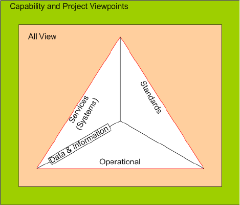
DoDAF 2.02 consists of viewpoint sets which together define an architecture. Figure 2 depicts the sets.
Encompassing all viewpoints are the capability and project viewpoints. A slightly narrower perspective is presented
by the all view containing an executive summary and integrated dictionary. The bulk of the architecture is
comprised of the operational viewpoints, the services (or systems) viewpoints, and technical standards viewpoints.
The data and information viewpoint spans both operational and services viewpoints.
Figure 2: DoDAF 2.02 viewpoints
The capability and project viewpoints are intended to show the context of a particular project and capture
relationships between projects. They also show how single or sets of capabilities together support the overall
enterprise missions and vision.
4

The all-view viewpoints provide a project’s vision, scope, goals, and assumptions. The all-view also describes the
intent of the architecture to ensure continuity in the face of personnel changes and an evolving environment.
The operational viewpoints collectively describe what a system does. A pure operational viewpoint (which is not
truly feasible) would describe what a system does with no concern as to how the system achieves its purposes
(DoDAF 2.02 refers to this as “materiel independent.”) Operational viewpoints are most closely related to the
logical viewpoints of other architectural models.
The services (or systems) viewpoints define how the system achieves its purpose. Where the operational viewpoints
describe logical entities and the logical flows among them, services (or systems) viewpoints define the physical
entities and connections and flows.
The data and information viewpoints define logical and physical data models. These viewpoints are appropriate for
database-intensive systems.
The standards viewpoints identify applicable standards and their implementations with respect to the systems being
defined.
III. Legacy Approach to Verification
Software verification has traditionally been part of the development view, using a classical verification V. Figure 3
from [KAG16B] is a typical representation of the verification process showing the verification activities and the
progress of fault introduction and identification.
Figure 3: Verification V
While most significant faults are introduced early in the project lifecycle, they are typically identified late in the
lifecycle. Unfortunately, late fault identification significantly increases the cost of fault remediation. A review of
sixteen studies shows [14] that, for software-intensive systems, the cost to fix errors increases rapidly as the lifecycle
progresses. Table 1 summarizes the results of that study.
5

Table 1: Relative cost-to-fix ratios
IV. Verification View
The VSM architecture can be viewed using the 4+1 model, augmented with a verification view. The approach taken
is to infuse verification as an architectural element parallel to the standard 4+1 views. The approach uses standard
verification techniques augmented with formal methods approaches to begin verification activities in the preliminary
design phase and continue through system operation. The verification view encompasses the other views, as do the
capability and all views of the DoDAF (Figure 2).
Figure 4: Verification View Added to 4+1
C. Development Verification View
During VSM flight software development, the verification view is addressed with the same attention and rigor as the
other architecture views, supporting the definition of each. The verification methodologies and techniques are best
practices and tool-driven to the extent feasible. We will discuss the implementation of the verification view in the
context of the standard 4+1 views.
6. Logical View Verification
The logical view specifies the capabilities provided by the system. It is documented in the concept of operations and
system specifications. As shown in Figure 3, the logical view, defined early in the lifecycle, is the primary source of
high cost-to-fix errors [13], [14]. Two techniques are at the core of VSM logical view verification: early prototyping
and model checking with assume-guarantee contracts.
Early prototypes of VSM software components are developed using the Modular Autonomous Systems Technology
(MAST) framework [2] which provides access to internal data allowing detailed monitoring and model checking of
6

key elements. The MAST environment facilitates hierarchical testing as components are added and integrated.
Incrementally implemented VSM functionality is initially tested in off-line simulations leading to testing in an
emulator environment (Gateway in a Box) that includes models of the spacecraft environment, dynamics, spacecraft
subsystems, and cooperating external subsystems such as visiting vehicles.
Assume-guarantee contracts provide a means to validate complex requirements that can be implemented or modeled
using large finite state machines with complex state spaces. The contracts are generated to describe expected
behavior of subsystems and the desirable safety and liveness properties that VSM interaction with the subsystems
must satisfy. They can be used to ensure algorithms satisfy fairness rules and also help identify potential race
conditions, deadlocks, livelocks.
The assume-guarantee contracts are derived from key VSM use cases using a standard format (Figure 5) [21] and
bound the allowed outputs and behavior of VSM and external subsystems based on input conditions. During design
and implementation, the contracts are decomposed and flow down to component-level contracts. This hierarchical
approach simplifies the verification problem. The contracts are implemented in a linear temporal logic language
such as TLA+ and, with a model of the driving state machine, model checked for safety properties and in some cases
liveness properties. The structure off the contract environment is shown in Figure 6.
Figure 5: Assume-guarantee contract template
Figure 6: Assume-guarantee contract hierarchy
7. Process View Verification
VSM consists of a many concurrent processes and supports varying degrees of autonomy ranging from completely
autonomous operations to manual control by a flight crew. The system includes planning, timeline management,
7
constraint checking and compliance, fault detection and management, and crew interfaces. Individual threads of
execution are tested in a conventional way using unit testing followed by increasing degrees of integration testing.
Unit testing is performed on developer and verification team workstations, progressing to Gateway in a Box
(Software in the Loop) to full integration testing using target hardware.
Process view issues are historically difficult to detect early in the lifecycle and potentially result in high-severity
problems if they escape to operations. As process view problems often result from specification errors or omissions,
model checking is particularly valuable in detecting and resolving them early in the lifecycle. An example process
view problem is interaction between two concurrent state machines resulting in a deadlock, or ambiguous behavior
due to race conditions. This type of problem is difficult to detect in standard testing but readily identifiable using
model checking.
8. Development
The traditional verification V (Figure 3) emphasizes verification from the perspective of the development view.
Consequently, there is available a large set of proven verification techniques and tools. The VSM team, in adopting
the full-lifecycle verification view, employs a robust set of development verification techniques. Standard mapping
techniques ensure that each software requirement is explicitly tested or verified using other means if not testable.
Static analysis tools are used to perform automated analysis of source code, checking for common programming
errors (such as set-use analysis) as well as compliance with coding standards. Metrics tools evaluate standard
complexity and testability metrics. And coverage tools assist test developers in ensuring that little-used functionality
is addressed.
9. Deployment
The deployment view deals with where capabilities reside and how elements of a capability cooperate. Gateway
consists of a set of modules, each with a Module System Manager (MSM) and a variety of subsystems. The modules
are provided by a variety of Gateway team members including international partners and visiting vehicles.
Therefore, at development time the VSM is limited to performing integration testing with relatively low fidelity
versions of the MSMs and subsystems with which it might interact. Integration testing with the full-fidelity MSMs
and subsystems will happen as part of formal verification at the end of the development lifecycle. This means there
is risk of emergent behavior in the interactions between VSM and the fully developed MSMs. The use of assume-
guarantee contracts on VSM-MSM interactions helps alleviate this problem by allowing VSM designers and
developers to verify functionality with respect to guarantees (and modeled) on subsystem performance that are
verified in the process of MSM and subsystem development.
Lab testing, starting with desktop models and progressing to flight-equivalent hardware ensure that computing
resources are adequate. For example, bus monitors ensure sufficient data bandwidth is available. Failure testing
verifies redundant systems handle postulated scenarios.
10. Scenario
VSM scenario view verification (Figure 7) relies on a tiered approach starting with offline simulations and ending
with large-scale hardware-in-the-loop testing. Scenario view verification exercises VSM at the subsystem level in
integrated environment using realistic operational data with dynamic variations in inputs and dispersed
environmental conditions (mode changes, system state changes, faults). It includes informal Monte Carlo type
analysis is used to assess VSM robustness, namely its ability to perform acceptably under conditions that vary from
those used during design and developmental testing. It also includes formal verification on a flight like platform
with high fidelity simulations. Scenario-based testing helps uncover subtle issues and data/configuration issues.
Scenario view verification is based on system requirements as illustrated using design reference scenarios such as
orbit change, visiting vehicle arrival or departure, and specified fault scenarios. In addition to run-time monitoring,
8

log files are produced to examine timing, mode change, and fine-grained event sequence behavior. Monte-Carlo
analysis is performed using analytically-derived probability density functions to perturb input, measurement, and
state values around the reference scenarios and to reasonably cover the feasible state and control space. Boundary
testing augments Monte Carlo testing to ensure correct behavior for state and control boundary conditions.
Figure 7: Scenario view verification
D. Operational Verification View
Operational verification consists primarily of runtime verification processes that are designed to detect situations in
which the software is not compliant with requirements or is on a path leading to a non-compliant state. Runtime
verification is particularly important for autonomous systems as there can be extended periods during which human
operator problem recognition and intervention is not feasible. Operational verification is a much more streamlined
process due to time and resource constraints. In devising operational verification approaches, three key issues are
addressed: access to data, verification approach, and a suitable toolset.
11. Approaches for Access to Data
The goal of data access is to acquire the necessary data while minimizing affecting the processes that are monitored.
The most efficient and intrusive approach is to closely integrate the verification functions with the operational
software, permitting access to internal data structures, data stores, global variables, and parameter lists. This
approach tightly couples the verification process to the monitored functional process, introducing the risk that the
verification process will adversely affect the monitored process.
An intermediate approach is to access only data that is available on software data buses, typically implemented
using shared memory. This approach decouples the verification processes from the monitored processes, but does
9
put additional load on the software data buses and can, therefore impact the monitored processes indirectly.
Software systems implemented using the NASA Core Flight System, for example, are good candidates for this
approach.
The least intrusive approach to data access for operational verification is via hardware data buses such as 1553
buses, telemetry feeds, or Time-Triggered Ethernet. This approach provides the ability to locate the operational
verification software processes so as to such that they don’t interfere with the operational software processes, either
on a processor with ample room or a separate, dedicated processor.
12. Verification Approaches
Verification approaches range from monitoring the instantaneous values to temporal logic model checking of the
operating code.
The simplest and most commonly used approach is monitoring the current state and inputs using a rule base. This
approach can be very light weight and is the approach most commonly used in legacy flight software systems. It
limits the detectable anomalous conditions to those that are instantaneously visible. We have observed that in
practice, this approach results in frequent operational difficulty, requiring operational notes or workarounds. For
example, on the first operational Space-X launch (15 November 2020), Space-X reported that three propellant heater
temperature sensors indicated out of range values. Subsequent real-time analysis revealed that the heaters were
operating correctly but the resistance limit was set excessively conservatively; so a workaround was implemented.
State history-based verification is a higher-order approach that reasons on time series, significantly increasing rule
scope and enabling detection of trends. In practice, this approach can function as a low-pass filter, reducing
susceptibility to noise. Using sequential data, verification software can detect and remediate race conditions and
other temporal issues. An extension of this approach [15] compares state history traces with validated traces and
reasons on the distance of actual state history traces and library traces. While the approach is viable, it requires a
large library of traces and is computationally expensive.
More advanced techniques project current state histories into the future and evaluate future states using temporal
logic formulas. A simple approach to implementing this technique uses simple linear state propagators to predict
future states to ensure current trends aren’t leading to trouble [20] an approach that is promising in preliminary
testing. A more robust approach is to model check a finite number of steps into the future, checking that the next,
starting at the present state, there are no feasible state trajectories that violate requirements. The most ambitious
approach [16], [17] is to do complete model checking using the current state as initial conditions and ascertain
whether there are currently paths to anomalous states. While this approach is attractive conceptually, it is impractical
due to issues of state space expansion and computational workload.
13. Operational Verification Tools
The VSM verification team evaluated a large number of candidate tools for operational verification using model
checking. Of these, three candidates are at a stage of technology readiness suitable for consideration for Gateway:
Copilot 3 [18], LOLA [19], and R2U2 [9]. Copilot 3, the current implementation of Copilot developed at NASA
Langley, is fairly tightly coupled and has been successfully used operationally on unmanned aerial vehicles using
the Core Flight System. LOLA, developed for the DLR in cooperation with Saarland University uses temporal logic
formulas to reason on data streams, either real-time or in off-line analysis. R2U2, developed jointly by NASA Ames
Research Center and Iowa State University can reason using temporal logic formulas on data streams and into the
future along a current trajectory using a state propagator [20]. We found no operationally deployed toolsets that
reason into the future using model checking, although R2U2 shows promise for finite horizon model checking.
10

V. Summary and Conclusions
Emerging autonomous systems such as the Gateway Vehicle System Manager are more vulnerable to latent defects
than systems with continuous human monitoring. Treating verification as an overarching architectural view can,
relative to the approach defined in the classic verification V, significantly reduce the cost to fix defects, ensure a
higher-quality system, and most importantly, increase reliability. The verification architectural view entails full-
lifecycle activities, with significant emphasis on early lifecycle verification using assume-guarantee contracts and
model checking. Incorporating verification in the logical, process, deployment, and scenario view increases the
opportunity to find defects early and reduces risk of defects making it into the operational system. Robust
operational verification is feasible using toolsets proven on NASA missions and helps protect the operating system
from undesirable behaviors. Future work will refine the verification view based on project experience and assess the
efficacy of the full-lifecycle and operational methodologies.
References
[1] Starek, J. A., Acikmese, B., Nesnas, I. A., Pavone, M., “Spacecraft Autonomy Challenges for Next-
Generation Space Missions,” Lecture Notes in Information Sciences, 2016
[2] Badger, J. M., Strawser, P., and Claunch, C., “A Distributed Hierarchical Framework for Autonomous
Spacecraft Control,” IEEE Aerospace Conference, Big Sky, Montana, 2019
[3] Ohi, D., Dabney, J. B., and Walter, C., “Independent Verification and Validation of Large System
Architectures,” NASA Spaceflight Flight Software Workshop, Jet Propulsion Laboratory, Pasadena,
California, December, 2010
[4] Dabney, J. B., and Rajagopal, P., “Architecture-Driven IV&V Planning,” NASA Flight Software
Workshop, San Antonio, Texas, December, 2018
[5] DoD Architecture Framework Version 2.0, Volume II: Architectural Data and Models Architect’s
Guide, U.S. Department of Defense, Washington, D.C., May, 2009
[6] Kruchten, P., “Architectural blueprints – the 4+1 view model of software architecture,” IEEE Software
Vol 12, No 6, November, 1995, pp 42 – 50
[7] Ryen, E., “Overview of the System Engineering Process,” North Dakota Department of
Transportation, 2008
[8] Zhao, Y., and Rozier, K. Y., “Formal Specification and Verification of a Coordination Protocol for an
Automated Air Traffic Control System,” Science of Computer Programming, V. 96, N. 3, 2014, pp
337 – 353
[9] Rozier, K., and Schumann, J., “R2U2: Tool Overview,” International Workshop on Competitions,
Usability, Benchmarks, Evaluation, and Standardisation for Runtime Verification Tools, Seattle,
Washington, 2017
[10] L. Karam, “The importance of a good software architecture,” https://apiumhub.com/tech-blog-barcelona/
importance-good-software-architecture, APIUMHUB, 2016.
[11] P. Kruchten, “Architectural blueprints – the 4+1 view model of software architecture,” IEEE Software Vol 12,
No 6, November, 1995, pp 42 – 50
[12] M. R. Barbacci and W. G. Wood, "Architecture tradeoff analyses of C4ISR products,” Technical Report CMU/
SEI-99-TR-014, Software Engineering Institute, 1999
11
[13] K. H. Gross, “Evaluation of verification approaches applied to a nonlinear control system,” M. S. Thesis, Air
Force Institute of Technology, 2016
[14] J. B. Dabney, G. Barber, and D. Ohi, "Estimating direct return on investment of independent verification and
validation," The 8th International Conference on Software Engineering and Applications, Cambridge, MA,
November 9 - 11, 2004
[15] A. Desai, T. Dreossi, S. A. Seshia, “Combining model checking and runtime verification for safe robotics,” UC
Berkely, 2017
[16] F. Baader, A. Bauer, M. Lippmann, “Runtime verification using a temporal description logic,” International
Symposium on Frontiers of Combining Systems, 2009
[17] K. Kejstova, P. Rockai, and J. Barmat, “From model checking to runtime verification and back,” International
Conference on Runtime Verification, Seattle, WA, 2017
[18] I. Perez, F. Dedden, A. Goodloe, “Copilot 3,” NASA/TM-2020-220587, NASA Langley, 2020
[19] S. Sebastian, “Runtime monitoring with LOLA,” MS Thesis, University of Saarland, Germany, 2016
[20] P. Zhang, R. Dureja, M. Cauwels, J. Zambreno, P. H. Jones, and K. Y. Rozier, “Model predictive runtime
verification for embedded platforms with real-time deadlines,” Iowa State University, to appear, 2021
[21] A. Benveniste, B. Caillaud, D. Nickovic, R. Passerone, J-B. Raclet, Ph. Reinkemeier, A. Sangiovanni-
Vincentelli, W. Damm, T. Henzinger, and K.G. Larsen, “Contracts for system design,” Foundations and Trends in
Electronic Design Automation, 2018
12
