
DoD Architecture Framework
Version 1.5
Core Architecture Data Model
All View
S
y
s
t
e
m
s
/
S
e
r
vi
c
e
s
V
i
e
w
T
e
c
h
n
i
c
a
l
S
t
a
n
d
a
r
d
s
V
i
e
w
Operational View
Volume II: Product Descriptions
23 April 2007
i
TABLE OF CONTENTS
SECTION PAGE
EXECUTIVE SUMMARY .....................................................................................................XIV
1 INTRODUCTION...................................................................................................................1-1
1.1 VOLUME II PURPOSE AND INTENDED AUDIENCE..............................1-1
1.1.1 Product Description Structure..............................................................1-2
1.2 OVERVIEW.......................................................................................................1-2
2 ARCHITECTURE BASICS - VIEWS, PRODUCTS, AND ARCHITECTURE DATA.2-1
2.1 ARCHITECTURE VIEWS...............................................................................2-1
2.1.1 Definition of the Operational View ......................................................2-1
2.1.2 Definition of the Systems View .............................................................2-1
2.1.3 Definition of the Technical Standards View........................................2-2
2.1.4 Definition of the All-Views....................................................................2-2
2.2 ARCHITECTURE PRODUCTS......................................................................2-2
2.3 ARCHITECTURE PRODUCT DEVELOPMENT........................................2-6
2.3.1 Product Development Methodology Support......................................2-6
2.3.2 Architecture Products and Levels of Detail.........................................2-8
2.3.3 Iterative Development of the Products ..............................................2-10
2.3.4 Product Templates...............................................................................2-10
2.3.5 Object-Orientation and the Unified Modeling Language Support.2-10
2.4 PRODUCT AND ARCHITECTURE DATA ELEMENT
RELATIONSHIPS...........................................................................................2-11
2.5 NET-CENTRIC GUIDANCE FOR ARCHITECTURE PRODUCTS.......2-12
2.6 CADM SUPPORT FOR ARCHITECTURE PRODUCTS .........................2-18
2.6.1 Overview and Summary of Common Data Structures – Data
Element Definitions..............................................................................2-20
3 ALL-VIEWS PRODUCTS.....................................................................................................3-1
3.1
OVERVIEW AND SUMMARY INFORMATION (AV-1) ...........................3-1
3.1.1 Overview and Summary Information (AV-1) – Product
Description.............................................................................................. 3-1
3.1.2 UML Representation.............................................................................3-2
3.1.3 Net-Centric Guidance for Overview and Summary Information
(AV-1)......................................................................................................3-2
ii
3.1.4 CADM Support for Overview and Summary Information (AV-1) ..3-3
3.2 INTEGRATED DICTIONARY (AV-2).........................................................3-16
3.2.1 Integrated Dictionary (AV-2) – Product Description.......................3-16
3.2.2 Taxonomies...........................................................................................3-17
3.2.3 UML Representation...........................................................................3-19
3.2.4 Net-Centric Guidance for Integrated Dictionary (AV-2).................3-19
3.2.5 CADM Support for Integrated Dictionary (AV-2)...........................3-20
4 OPERATIONAL VIEW PRODUCTS..................................................................................4-1
4.1 HIGH-LEVEL OPERATIONAL CONCEPT GRAPHIC (OV-1)................4-1
4.1.1 High-Level Operational Concept Graphic (OV-1) – Product
Description..............................................................................................4-1
4.1.2 UML Representation.............................................................................4-3
4.1.3 Net-Centric Guidance for High-Level Operational Concept
Graphic (OV-1) ......................................................................................4-3
4.1.4 CADM Support for High-Level Operational Concept Graphic
(OV-1)......................................................................................................4-4
4.2 OPERATIONAL NODE CONNECTIVITY DESCRIPTION (OV-2).......4-10
4.2.1 Operational Node Connectivity Description (OV-2) – Product
Description............................................................................................4-10
4.2.2 UML Representation...........................................................................4-13
4.2.3 Net-Centric Guidance for Node Connectivity Description (OV-2) .4-14
4.2.4 CADM Support for Operational Node Connectivity Description
(OV-2)....................................................................................................4-15
4.3 OPERATIONAL INFORMATION EXCHANGE MATRIX (OV-3) ........4-24
4.3.1 Operational Information Exchange Matrix (OV-3) – Product
Description............................................................................................4-24
4.3.2 UML Representation...........................................................................4-26
4.3.3 Net-Centric Guidance for Operational Information Exchange
Matrix (OV-3).......................................................................................4-26
4.3.4 CADM Support for Operational Information Exchange Matrix
(OV-3)....................................................................................................4-27
4.4 ORGANIZATIONAL RELATIONSHIPS CHART (OV-4) .......................4-34
4.4.1 Organizational Relationships Chart (OV-4) – Product
Description............................................................................................4-34
4.4.2 UML Representation...........................................................................4-35
iii
4.4.3 Net-Centric Guidance for Organizational Relationships Chart
(OV-4)....................................................................................................4-35
4.4.4 CADM Support for Organizational Relationships Chart (OV-4)...4-36
4.5 OPERATIONAL ACTIVITY MODEL (OV-5)............................................4-40
4.5.1 Operational Activity Model (OV-5) – Product Description.............4-40
4.5.2 UML Representation...........................................................................4-43
4.5.3 Net-Centric Guidance for Operational Activity Model (OV-5).......4-44
4.5.4 CADM Support for Operational Activity Model (OV-5).................4-45
4.6 OPERATIONAL ACTIVITY SEQUENCE AND TIMING
DESCRIPTIONS (OV-6A, 6B, AND 6C) ...................................................... 4-52
4.6.1 Overview of Operational Activity Sequence and Timing
Descriptions.......................................................................................... 4-52
4.6.2 CADM Support for Operational Activity Sequences and Threads
(OV-6)....................................................................................................4-52
4.6.3 Operational Rules Model (OV-6a) .....................................................4-54
4.6.4 UML Representation...........................................................................4-56
4.6.5 Net-Centric Guidance for Operational Rules Model (OV-6a).........4-56
4.6.6 CADM Support for Operational Rules Model (OV-6a)...................4-57
4.6.7 Operational State Transition Description (OV-6b)..........................4-61
4.6.8 UML Representation...........................................................................4-64
4.6.9 Net-Centric Guidance for Operational State Transition
Description (OV-6b).............................................................................4-64
4.6.10 CADM Support for Operational State Transition Description
(OV-6b) .................................................................................................4-65
4.6.11 Operational Event-Trace Description (OV-6c).................................4-68
4.6.12 UML Representation...........................................................................4-71
4.6.13 Net-Centric Guidance for Operational Event-Trace Description
(OV-6c)..................................................................................................4-72
4.6.14 CADM Support for Operational Event-Trace Description (OV-
6c) .......................................................................................................... 4-73
4.7 LOGICAL DATA MODEL (OV-7)...............................................................4-76
4.7.1 Logical Data Model (OV-7) – Product Description..........................4-76
4.7.2 UML Representation...........................................................................4-77
4.7.3 Net-Centric Guidance for Logical Data Model (OV-7)....................4-78
4.7.4 CADM Support for Logical Data Model (OV-7)..............................4-79
iv
5 SYSTEMS AND SERVICES VIEW PRODUCTS..............................................................5-1
5.1 SYSTEMS AND SERVICES INTERFACE DESCRIPTION (SV-1)...........5-1
5.1.1 Systems Interface Description (SV-1) – Product Description............5-1
5.1.2 UML Representation.............................................................................5-5
5.1.3 Net-Centric Guidance for Systems and Services Interface
Description (SV-1).................................................................................. 5-7
5.1.4 CADM Support for Systems and Services Interface
Description (SV-1)................................................................................ 5-10
5.2 SYSTEMS AND SERVICES COMMUNICATIONS DESCRIPTION
(SV-2) ................................................................................................................ 5-16
5.2.1 Systems Communications Description (SV-2) – Product
Description............................................................................................ 5-16
5.2.2 UML Representation...........................................................................5-17
5.2.3 Net-Centric Guidance Systems and Services Communications
Description (SV-2)................................................................................5-18
5.2.4 CADM Support for Systems and Services Communications
Description (SV-2)................................................................................5-20
5.3 SYSTEMS-SYSTEMS, SERVICES-SYSTEMS, SERVICES-SERIVCES
MATRICES (SV-3)..........................................................................................5-24
5.3.1 Systems-Systems Matrix (SV-3) – Product Description...................5-24
5.3.2 UML Representation...........................................................................5-24
5.3.3 Net-Centric Guidance for Services-Systems & Services-Services
Matrices (SV-3) ....................................................................................5-25
5.3.4 CADM Support for Systems-Systems, Services-Systems, and
Services-Services Matrices (SV-3)...................................................... 5-25
5.4 SYSTEMS AND SERVICES FUNCTIONALITY DESCRIPTION
(SV-4A AND 4B)..............................................................................................5-28
5.4.1 Systems Functionality Description (SV-4a) – Product
Description............................................................................................5-28
5.4.2 UML Representation...........................................................................5-29
5.4.3 Net-Centric Guidance for Services Functionality Description
(SV-4b).................................................................................................. 5-32
5.4.4
CADM Support for Systems and Services Functionality
Description (SV-4)................................................................................ 5-35
5.5 OPERATIONAL ACTIVITY TO SYSTEMS FUNCTION AND
SERVICES TRACEABILITY MATRICES (SV-5A, 5B, AND 5C)........... 5-39
v
5.5.1 Operational Activity to Systems Function Traceability Matrix
(SV-5a and b) – Product Description................................................. 5-39
5.5.2 UML Representation...........................................................................5-42
5.5.3 Net-Centric Guidance for Operational Activity to Services
Traceability Matrix (SV-5c)................................................................5-42
5.5.4 CADM Support for Operational Activity to Systems Function
and Services Traceability Matrices (SV-5)........................................ 5-43
5.6 SYSTEMS AND SERVICES DATA EXCHANGE MATRIX (SV-6)........5-47
5.6.1 Systems Data Exchange Matrix (SV-6) – Product Description.......5-47
5.6.2 UML Representation...........................................................................5-48
5.6.3 Net-Centric Guidance for Systems and Services Data Exchange
Matrix (SV-6) .......................................................................................5-49
5.6.4 CADM Support for Systems and Services Data Exchange
Matrix (SV-6) ....................................................................................... 5-50
5.7 SYSTEMS AND SERVICES PERFORMANCE PARAMETERS
MATRIX (SV-7)...............................................................................................5-54
5.7.1 Systems Performance Parameters Matrix (SV-7) – Product
Description............................................................................................5-54
5.7.2 UML Representation...........................................................................5-55
5.7.3 Net-Centric Guidance for Systems and Services Performance
Parameters Matrix (SV-7)...................................................................5-55
5.7.4 CADM Support for Systems and Services Performance
Parameters Matrix (SV-7)...................................................................5-56
5.8 SYSTEMS AND SERVICES EVOLUTION DESCRIPTION (SV-8)........5-60
5.8.1 Systems Evolution Description (SV-8) – Product Description.........5-60
5.8.2 UML Representation...........................................................................5-61
5.8.3 Net-Centric Guidance for Systems and Services Evolution
Description (SV-8)................................................................................ 5-61
5.8.4 CADM Support for Systems and Services Evolution Description
(SV-8) .................................................................................................... 5-62
5.9 SYSTEMS TECHNOLOGY FORECAST (SV-9)........................................5-64
5.9.1 Systems Technology Forecast (SV-9) – Product Description...........5-64
5.9.2 UML Representation...........................................................................5-66
5.9.3 Net-Centric Guidance for Systems Technology Forecast (SV-9) ....5-66
5.9.4 CADM Support for Systems Technology Forecast (SV-9)...............5-66
vi
5.10 SYSTEMS AND SERVICES FUNCTIONALITY SEQUENCE AND
TIMING DESCRIPTIONS (SV-10A, 10B, AND 10C).................................5-69
5.10.1 Overview of Systems and Services Functionality Sequence and
Timing Descriptions............................................................................. 5-69
5.10.2 CADM Support for Systems and Services Functionality
Sequences and Threads ....................................................................... 5-69
5.10.3 Systems Rules Model (SV-10a) – Product Description.....................5-70
5.10.4 UML Representation...........................................................................5-72
5.10.5 Net-Centric Guidance for Services Rules Model (SV-10a)..............5-72
5.10.6 CADM Support for Systems and Services Rules Model (SV-10a)..5-73
5.10.7 Systems State Transition Description (SV-10b) – Product
Description............................................................................................ 5-76
5.10.8 UML Representation...........................................................................5-77
5.10.9 Net-Centric Guidance for Services State Transition Description
(SV-10b)................................................................................................ 5-77
5.10.10 CADM Support for Systems and Services State Transition
Description (SV-10b) ...........................................................................5-77
5.10.11 Systems Event-Trace Description (SV-10c) – Product
Description............................................................................................5-80
5.10.12 UML Representation...........................................................................5-81
5.10.13 Net-Centric Guidance for Services Event-Trace Description
(SV-10c).................................................................................................5-81
5.10.14 CADM Support for Systems and Services Event-Trace
Description (SV-10c)............................................................................ 5-83
5.11 PHYSICAL SCHEMA (SV-11)......................................................................5-86
5.11.1 Physical Schema (SV-11) – Product Description ..............................5-86
5.11.2 UML Representation...........................................................................5-87
5.11.3 Net-Centric Guidance for Physical Schema (SV-11)........................5-88
5.11.4 CADM Support for Physical Schema (SV-11) ..................................5-89
6 TECHNICAL STANDARDS VIEW PRODUCTS..............................................................6-1
6.1 TECHNICAL STANDARDS PROFILE (TV-1) ............................................6-1
6.1.1 Technical Standards Profile (TV-1) – Product Description...............6-1
6.1.2 UML Representation.............................................................................6-5
6.1.3 Net-Centric Guidance for Technical Standards Profile (TV-1) ........6-6
6.1.4 CADM Support for Technical Standards View (TV).........................6-6
vii
6.1.5 CADM Support for Technical Standards Profile (TV-1)...................6-6
6.2 TECHNICAL STANDARDS FORECAST (TV-2) ........................................6-9
6.2.1 Technical Standards Forecast (TV-2) – Product Description............6-9
6.2.2 UML Representation.............................................................................6-9
6.2.3 Net-Centric Guidance for Technical Standards Forecast (TV-2) .....6-9
6.2.4 CADM Support for Technical Standards Forecast (TV-2)..............6-10
7 FRAMEWORK ARCHITECTURE DATA ELEMENT RELATIONSHIPS..................7-1
7.1 OVERVIEW.......................................................................................................7-1
7.2 ARCHITECTURE DATA ELEMENT RELATIONSHIPS ACROSS
THREE VIEWS.................................................................................................7-2
7.3 OPERATIONAL VIEW ARCHITECTURE DATA ELEMENT
RELATIONSHIPS.............................................................................................7-4
7.4 SYSTEMS VIEW ARCHITECTURE DATA ELEMENT
RELATIONSHIPS.............................................................................................7-5
7.5 SYSTEM ELEMENTS THAT MAP TO STANDARDS...............................7-6
7.6 SUMMARY OF ARCHITECTURE DATA ELEMENT
RELATIONSHIPS.............................................................................................7-7
ANNEX A GLOSSARY ...........................................................................................................A-1
ANNEX B DICTIONARY OF TERMS.................................................................................. B-1
ANNEX C DICTIONARY OF UML TERMS.......................................................................C-1
ANNEX D CADM KEY ENTITY DEFINITIONS................................................................D-1
ANNEX E REFERENCES....................................................................................................... E-1
viii
LIST OF FIGURES
FIGURE PAGE
Figure 2-1 Fundamental Linkages Among the Views ............................................................ 2-1
Figure 2-2 Architecture Products by Use ................................................................................2-5
Figure 2-3 Example Structured Analysis.................................................................................2-7
Figure 2-4 Example Object-Oriented.......................................................................................2-8
Figure 2-5 Perspectives and Decomposition Levels................................................................ 2-9
Figure 2-6 Fundamental Linkages Among the Products and Architecture Data
Elements .............................................................................................................2-12
Figure 2-7 CADM Support for Architecture Products........................................................2-19
Figure 3-1 Overview and Summary Information (AV-1) - Representative Format............3-2
Figure 3-2 CADM Diagram for Overview and Summary Information (AV-1)...................3-5
Figure 3-3 Taxonomies Used in Products.............................................................................. 3-19
Figure 3-4 CADM Diagram for Integrated Dictionary (AV-2)........................................... 3-21
Figure 4-1 DoD Electronic Commerce Concept of Operations (OV-1)................................ 4-2
Figure 4-2 Joint Task Force Concept of Operations (OV-1) .................................................4-3
Figure 4-3 Joint Network Enabled Weapon (NEW) Capability Operational Concept
Graphic (OV-1)....................................................................................................4-4
Figure 4-4 CADM Diagram for High-Level Operational Concept Graphic (OV-1)........... 4-6
Figure 4-5 Operational Node Connectivity Description (OV-2) Template.........................4-12
Figure 4-6 Notional Example of an OV-2 Depicting Service Providers.............................. 4-13
Figure 4-7 UML Operational Node Connectivity Description (OV-2) Template.............. 4-13
Figure 4-8 CADM Diagram for Operational Node Connectivity Description (OV-2)......4-17
Figure 4-9 Operational Information Exchange Matrix (OV-3) – Template ......................4-25
Figure 4-10 CADM Diagram for Operational Information Exchange Matrix (OV-3)..... 4-28
Figure 4-11 Organizational Relationships Chart (OV-4) – Template.................................4-35
Figure 4-12 UML OV-4 Sample..............................................................................................4-35
Figure 4-13 CADM Diagram for Organizational Relationships Chart (OV-4).................4-37
Figure 4-14 Operational Activity Hierarchy Chart and Operational Activity Diagram
(OV-5) – Templates ...........................................................................................4-42
Figure 4-15 Operational Activity Model (OV-5) – Template with Notional
Annotations........................................................................................................4-43
Figure 4-16 UML Example OV-5........................................................................................... 4-44
Figure 4-17 CADM Diagram for Operational Activity Model (OV-5)...............................4-47
ix
Figure 4-18 CADM Diagram for Operational Activity Sequences and Threads (OV-6)..4-53
Figure 4-19 Operational Rules Model (OV-6a) – Action Assertion Example.................... 4-55
Figure 4-20 CADM Diagram for Operational Rules Model (OV-6a)................................. 4-58
Figure 4-21 Operational State Transition Description – High-Level Template ................4-62
Figure 4-22 Anatomy of an Executable Operational Architecture..................................... 4-63
Figure 4-23 Sample Histograms Showing Results of a Simulation Run.............................4-64
Figure 4-24 CADM Diagram for Operational State Transition Description (OV-6b)......4-66
Figure 4-25 Operational Event-Trace Description (OV-6c) – UML-type Template......... 4-70
Figure 4-26 Operational Event-Trace Description (OV-6c) – IDEF3 Example.................4-71
Figure 4-27 UML Representation of an Operational Event-Trace (OV-6c) ......................4-71
Figure 4-28 CADM Diagram for Operational Event-Trace Description (OV-6c).............4-74
Figure 4-29 Logical Data Model (OV-7) – Template............................................................ 4-77
Figure 4-30 UML Class Diagram for Logical Data Model (OV-7) – Template................. 4-78
Figure 4-31 CADM Diagram for Logical Data Model (OV-7) ............................................4-79
Figure 5-1 SV-1 Internodal Template Showing Systems........................................................5-3
Figure 5-2 SV-1 Internodal Version – Node Edge to Node Edge Showing System
Functions..............................................................................................................5-3
Figure 5-3 SV-1 Internodal Version Showing System-System Interfaces – Template........5-4
Figure 5-4 SV-1 Intranodal Version – Template .................................................................... 5-4
Figure 5-5 SV-1 Intrasystem Version – Example Showing a KI, a Database, and Other
Software and Hardware Items...........................................................................5-5
Figure 5-6 UML Node/Component Diagram for SV-1 Internodal Version Showing
Systems – Template............................................................................................. 5-6
Figure 5-7 UML Node/Component Diagram for SV-1 Internodal Version Showing
System-System Interfaces – Template...............................................................5-6
Figure 5-8 Notional Example: Services Interface Description (SV-1): Layer 1 Example...5-9
Figure 5-9 Notional Example: Services Interface Description (SV-1): Layer 2 Example.5-10
Figure 5-10 CADM Diagram for Systems and Services Interface Description (SV-1)......5-12
Figure 5-11 Systems Communications Description, Internodal Version (SV-2) –
Template.............................................................................................................5-17
Figure 5-12 Systems Communications Description, Intranodal Version (SV-2) –
Template.............................................................................................................5-17
Figure 5-13 UML Representation for SV-2........................................................................... 5-18
Figure 5-14 Notional Example: Services Interface Description (SV-2): Layer 2
Example..............................................................................................................5-20
x
Figure 5-15 CADM Diagram for Systems and Services Communications Description
(SV-2)..................................................................................................................5-22
Figure 5-16 Systems-Systems Matrix (SV-3) – Template.....................................................5-24
Figure 5-17 CADM Diagram for Systems-Systems, Services-Systems, and Services-
Services Matrix (SV-3)......................................................................................5-26
Figure 5-18 Systems Functionality Description (SV-4a) – Template (Functional
Decomposition) ..................................................................................................5-29
Figure 5-19 Systems Functionality Description (SV-4a) – Template (Data Flow
Diagram)............................................................................................................. 5-29
Figure 5-20 UML Use Case Diagram for Systems Functionality Description (SV-4) ....... 5-30
Figure 5-21 UML Class Diagram for Systems Functionality Description (SV-4a)............5-31
Figure 5-22 Sequence Diagram...............................................................................................5-31
Figure 5-23 Notional Example: Service Functionality Description (SV-4b): Functional
Decomposition.................................................................................................... 5-34
Figure 5-24 Notional Example: Service Functionality Description (SV-4b): Data Flow
Diagram..............................................................................................................5-35
Figure 5-25 CADM Diagram for Systems and Services Functionality Description (SV-
4).......................................................................................................................... 5-36
Figure 5-26 Operational Activity to Systems Function Traceability Matrix (SV-5a)....... 5-40
Figure 5-27 Capability to System Traceability Matrix (SV-5b)..........................................5-41
Figure 5-28 Notional Example: Operational Activity to Services Traceability Matrix
(SV-5c)................................................................................................................5-43
Figure 5-29 CADM Diagram for Operational Activity to Systems Function and
Services Traceability Matrices (SV-5).............................................................5-45
Figure 5-30 Systems Data Exchange Matrix (SV-6) – Template......................................... 5-48
Figure 5-31 UML Logical Service Realization Diagram (SV-6).......................................... 5-49
Figure 5-32 CADM Diagram for Systems and Services Data Exchange Matrix (SV-6)... 5-52
Figure 5-33 Systems Performance Parameters Matrix (SV-7) – Notional Example.........5-55
Figure 5-34 CADM Diagram for Technology Systems and Services Performance
Parameters Matrix (SV-7)................................................................................5-58
Figure 5-35 Systems Evolution Description (SV-8) – Migration......................................... 5-60
Figure 5-36 Systems Evolution Description (SV-8) – Evolution.......................................... 5-61
Figure 5-37 CADM Diagram for Systems and Services Evolution Description (SV-8) ....5-62
Figure 5-38 CADM Diagram for Systems Technology Forecast (SV-9)............................. 5-67
Figure 5-39 CADM Diagram for Systems and Services Functionality Sequence and
Threads...............................................................................................................5-70
xi
Figure 5-40 Rules Model (SV-10a) – Action Assertion Example.........................................5-72
Figure 5-41 CADM Diagram for Systems and Services Rules Model (SV-10a) ................5-75
Figure 5-42 Systems State Transition Description (SV-10b) – High-Level Template....... 5-77
Figure 5-43 CADM Diagram for Systems and Services State Transition Description
(SV-10b).............................................................................................................. 5-79
Figure 5-44 Systems Event-Trace Description (SV-10c) – Template.................................. 5-81
Figure 5-45 Notional Example: Services Event-Trace Description (SV-10c)..................... 5-83
Figure 5-46 CADM Diagram for Systems and Services Event-Trace Description (SV-
10c)......................................................................................................................5-84
Figure 5-47 Schema (SV-11) – Representation Options....................................................... 5-87
Figure 5-48 UML Class Diagram for Physical Schema (SV-11)..........................................5-88
Figure 5-49 CADM Diagram for Physical Schema (SV-11).................................................5-90
Figure 6-1 Systems Products Associated with Standards ......................................................6-3
Figure 6-2 CADM Diagram for Joint Technical Architecture..............................................6-7
Figure 6-3 CADM Diagram for Technical Standards Forecast (TV-2)..............................6-11
Figure 7-1 Major Product Relationships................................................................................. 7-3
Figure 7-2 Operational View Product Relationships.............................................................. 7-4
Figure 7-3 Systems View Product Relationships.....................................................................7-5
Figure 7-4 Detail of Systems Elements that are Associated with Standards........................7-6
xii
LIST OF TABLES
TABLE PAGE
Table 1-1 Organization of Volume II.......................................................................................1-2
Table 2-1 List of Products.........................................................................................................2-3
Table 2-2 Data Element Definitions for Common Data Structures....................................2-20
Table 3-1 Data Element Definitions for Overview and Summary Information (AV-1)...... 3-6
Table 3-2 Data Element Definitions for Integrated Dictionary (AV-2)..............................3-23
Table 4-1 Data Element Definitions for High-Level Operational Concept Graphic
(OV-1).....................................................................................................................4-7
Table 4-2 Data Element Definitions for Operational Node Connectivity Description
(OV-2)...................................................................................................................4-18
Table 4-3 Data Element Definitions for Operational Information Exchange Matrix
(OV-3)...................................................................................................................4-32
Table 4-4 Data Element Definitions for Organizational Relationships Chart (OV-4)......4-38
Table 4-5 Data Element Definitions for Operational Activity Model (OV-5)....................4-49
Table 4-6 Data Element Definitions for Operational Rules Model (OV-6a)...................... 4-59
Table 4-7 Data Element Definitions for Operational State Transition Description
(OV-6b) ................................................................................................................4-67
Table 4-8 Data Element Definitions for Logical Data Model (OV-7) .................................4-80
Table 5-1 Data Element Definitions for Systems and Services Interface Description
(SV-1) ................................................................................................................... 5-13
Table 5-2 Data Element Definitions for Systems and Services Communications
Description (SV-2)............................................................................................... 5-23
Table 5-3 Data Element Definitions for Systems-Systems, Services-Systems, and
Services-Services Matrices (SV-3)..................................................................... 5-27
Table 5-4 Data Element Definitions for Systems and Services Data Exchange Matrix
(SV-6) ................................................................................................................... 5-53
Table 5-5 Data Element Definitions for Systems and Services Performance Matrix
(SV-7) ................................................................................................................... 5-59
Table 5-6 Data Element Definitions for Systems and Services Evolution Description
(SV-8) ................................................................................................................... 5-63
Table 5-7 Systems Technology Forecast (SV-9) – Notional Example .................................5-65
Table 5-8 Systems Technology Forecast (SV-9) – Template................................................ 5-65
Table 5-9 Data Element Definitions for Systems Technology Forecast (SV-9)..................5-68
Table 5-10 Data Element Definitions for Physical Schema (SV-11)....................................5-91
xiii
Table 6-1 Technical Standards Profile (TV-1) Template....................................................... 6-2
Table 6-2 TV-1 Template with Corresponding System Elements.........................................6-4
Table 6-3 TV-1 Template for Systems with Corresponding Time Periods .......................... 6-5
Table 6-4 Data Element Definitions for Technical Standards Profile (TV-1)...................... 6-8
Table 7-1 Detailed Architecture Data Element Relationships............................................... 7-7

xiv
EXECUTIVE SUMMARY
Architectures within the Department of Defense (DoD) are created for a number of reasons.
From a compliance perspective, the DoD is compelled by law and policy (i.e., Clinger-Cohen
Act, Office of Management and Budget (OMB) Circular A-130) to develop architectures. From
a practical perspective, experience has demonstrated that the management of large organizations
employing sophisticated systems and technologies in pursuit of joint missions demands a
structured, repeatable method for evaluating investments and investment alternatives,
implementing organizational change, creating new systems, and deploying new technologies.
Towards this end, the DoD Architecture Framework (DoDAF) was established as a guide for the
development of architectures.
The DoDAF provides the guidance and rules for developing, representing, and understanding
architectures based on a common denominator across DoD, Joint, and multinational boundaries.
It provides external stakeholders with insight into how the DoD develops architectures. The
DoDAF ensures that architecture descriptions can be compared and related across programs,
mission areas, and ultimately, the enterprise, thus, establishing the foundation for analyses that
supports decision-making processes throughout the DoD.
As the Department takes appropriate strides to ensure advancement of the Information
Technology (IT) environment, it becomes essential for the DoDAF to transform to sufficiently
support new technologies. A significant evolution occurring today is the Department’s
transformation to a new type of information intensive warfare known as Net-Centric Warfare
(NCW). NCW focuses on generating combat power from the effective linking or networking of
the warfighting enterprise, and making essential information available to authenticated,
authorized users when and where they need it. This ability is at the heart of net-centricity and
essential to achieving Net-Centric Operations (NCO).
DoDAF v1.5 is a transitional version that responds to the DoD’s migration towards NCW. It
applies essential net-centric concepts
1
in transforming the DoDAF and acknowledges that the
advances in enabling technologies – such as services within a Service Oriented Architecture
(SOA) – are fundamental to realizing the Department’s Net-Centric Vision
2
. DoDAF v1.5
addresses the immediate net-centric architecture development needs of the Department while
maintaining backward compatibility with DoDAF v1.0.
In addition to net-centric guidance, DoDAF v1.5 places more emphasis on architecture data,
rather than the products, introduces the concept of federated architectures, and incorporates the
Core Architecture Data Model (CADM) as an integral component of the DoDAF. These aspects
1
Reference DoDAF v1.5 Volume II for further information on the following net-centric concepts and their application to DoDAF: 1) Populate
the Net-Centric Environment , 2) Utilize the Net-Centric Environment , 3) Accommodate the Unanticipated User, 4) Promote the Use of
Communities Of Interest (COI), 5) Support Shared Infrastructure
2
2005 National Defense Strategy
Architecture: the structure of components, their relationships, and the principles and
guidelines governing their design and evolution over time.
DoD Integrated Architecture Panel,
1995, based on IEEE STD 610.12

xv
prepare the way for more efficient and flexible use and reuse of architecture data, enabling
broader utility for decision makers and process
3
owners.
The DoDAF is a three-volume set that inclusively covers the concept of the architecture
framework, development of architecture descriptions, and management of architecture data.
• Volume I introduces the DoDAF framework and addresses the development,
use, governance, and maintenance of architecture data.
• Volume II outlines the essential aspects of architecture development and
applies the net-centric concepts to the DoDAF products.
• Volume III introduces the architecture data management strategy and
describes the pre-release CADM v1.5, which includes the data elements and
business rules for the relationships that enable consistent data representation
across architectures.
An Online Journal, hosted on the DoD Architecture Registry System (DARS) website
(https://dars1.army.mil), replaces the DoDAF v1.0 Desk Book and is designed to capture
development best practices, architecture analytical techniques, and showcase exemplar
architectures.
The DoDAF will continue to evolve to meet the growing needs of decision makers in the
Net-Centric Environment (NCE). Going forward, architectures will need to capture the
development of a new generation of net-centric capabilities stemming from operational insights
gained in Afghanistan and Iraq. As the maturation of the Global Information Grid (GIG)
continues through GIG Capability Increments (an incremental time frame approach to the
delivery of GIG-enabling capabilities), architectures will be a factor in evaluating increment
investments, development, and performance at the mission portfolio levels. As the DoD
increases its use of architecture data for decision-making processes, architects will need to
understand how to aggregate the data for presentation purposes at the enterprise level. The
DoDAF plays a critical role in the development of architectures and will continue to improve its
support for the increasing uses of architecture data.
3
CJCS Instruction 3170.01E, Joint Capabilities Integration and Development System (JCIDS); DoD Directive 7045.14, Planning, Programming,
Budgeting, and Execution (PPBE); DoD Directive 5000.1, The Defense Acquisition System (DAS); DoD Directive 8115.01, Information
Technology Portfolio Management (PfM)
1-1
1 INTRODUCTION
1.1 VOLUME II PURPOSE AND INTENDED AUDIENCE
The purpose of the DoDAF v1.5 Volume II is to define, provide a purpose for, and describe
in detail each Framework product. This volume is organized with various readers in mind.
For the manager who needs to lead architecture development projects and who may need to
use an architecture to make acquisition, budgeting, or resourcing decisions, product definition
and product purpose subsections are provided in each product section to:
- Help these managers understand the architecture components or products.
- Provide an appreciation of the potential level of effort involved in developing
architectures.
- Assist in discerning the potential uses of an architecture.
For the architect and engineering team who need to develop architecture products for high-
level decision makers for use in decision support analysis, a detailed product description and
an architecture data element table subsection are provided in each product section to:
- Enable the architect and his team to identify products to be included in the
architecture based on the architecture’s intended use (see Figure 2-2,
Architecture Products by Use).
- Determine architecture data needs.
- Identify sources for the architecture data.
- Analyze and relate the architecture data gathered.
- Compose the architecture data into architecture products.
A Net-Centric Guidance subsection is provided in each product section. With the same
architectural vision, the program manager, Component-level CIOs, and chief architects who are
guiding the development of architectures, which include net-centric components, should view the
Net-Centric Guidance subsections with their individual perspectives and duties to:
- Assist in developing architecture products that show how programs and
Component organizations are:
• Using and consuming information and capabilities from the NCE
• Facilitating widespread use of information and capabilities beyond
their initial predefined set of users
• Utilizing collaborative communities to make information and
capabilities more understandable in the NCE
• Providing and consuming shared infrastructure
- Aid in developing net-centric architectures compliant with the Net-Centric
Operations and Warfare Reference Model (NCOW RM)
- Support program level architecture reviews in support of the Warfighter,
Business, Intelligence, and Enterprise Information Environment Mission
Areas portfolios
This document is organized in the following manner:

1-2
Section Content
Section 1
Introduction – Identifies the purpose and intended audience of Volume II.
Provides a brief overview of DoDAF terms.
Section 2
Architecture Basics – Views, Products, and Architecture Data – Provides
an overview of basic concepts of the DoD architecture approach and
introduces the net-centric concepts.
Section 3 All-Views Products – Provides All-View product descriptions.
Section 4
Operational View Products – Provides Operational View product
descriptions.
Section 5
Systems and Services View Products – Provides Systems and Services
View product descriptions.
Section 6
Technical Standards View Products – Provides Technical Standards View
product descriptions.
Section 7
Framework Architecture Data Element Relationships – Contains details
of the architecture data element and product relationships.
Table 1-1 Organization of Volume II
The product definitions are provided according to the format described below.
1.1.1 Product Description Structure
Products for each view are presented individually, with the following separate subsections:
1. A product overview (what is it)
2. A brief statement on the purpose of the product (why is it useful)
3. A detailed description that includes:
- Narrative details about the product and its representation in Structured Analysis
(SA) and in Object-Oriented (OO) notation, where applicable
- One or more generic templates and/or examples (For most of the products, one or
more generic templates are shown to illustrate the basic format of the product;
when a generic template is not appropriate, one or more examples are shown.)
4. Net-centric guidance that includes:
- An updated purpose of the view in a NCE
- Detailed guidance for tailoring the product to the net-centric concepts
- Example net-centric product diagrams, as applicable
5. CADM information space and model, and as applicable, data element and
relationship table
1.2 OVERVIEW
The DoDAF v1.5 defines a common approach for DoD architecture description development,
presentation, and integration. The DoDAF v1.5 is a net-centric update to the framework which
provides a common approach to DoD net-centric architecture development and includes
1-3
guidance to programs, managers, and architects who are developing systems that operate in the
NCE as mandated by DoD CIO policies, guidance, and instruction. The net-centric update of
DoDAF v1.5 leverages the previous DoDAF v1.0 to describe three types of architectures:
Traditional, Net-Centric, and Hybrid (a mix of traditional and net-centric).
An architecture description is a representation of a defined domain, as of a current or future
point in time, in terms of its component parts, how those parts function, the rules and constraints
under which those parts function, and how those parts relate to each other and to the
environment. Within the DoDAF, architectures are described in terms of four views: Operational
View (OV), Systems and Services View (SV), Technical Standards View (TV), and All-View
(AV). An architecture description is composed of architecture products that are interrelated
within each view and are interrelated across views. Architecture products are those graphical,
textual, and tabular items that are developed in the course of:
• Gathering architecture data
• Identifying their composition into related architecture components or composites
• Modeling the relationships among those composites
Underlying the products is the CADM, which defines a standard set of architecture data entities
and relationships for architecture data.
The term architecture is generally used both to refer to an architecture description and an
architecture implementation. An architecture description is a representation of a current or
postulated real-world configuration of resources, rules, and relationships. Once the
representation enters the design, development, and acquisition portion of the system
development life-cycle process, the architecture description is then transformed into a real
implementation of capabilities and assets in the field. The Framework itself does not address this
representation-to-implementation transformation process but references policies that are relevant
to that process.
Hereafter in this document, the term architecture will be used as a shortened reference to
architecture description. Occasionally, the term architecture description is used for emphasis.

2-1
2 ARCHITECTURE BASICS - VIEWS, PRODUCTS, AND
ARCHITECTURE DATA
2.1 ARCHITECTURE VIEWS
As defined in Volume I, the term integrated architecture refers to one in which architecture
data elements are uniquely identified and consistently used across all products and views within
the architecture. In most cases, an integrated architecture description has an OV, SV, TV, and an
All View (AV) that are integrated with each other (i.e., there are common points of reference
linking the OV and SV and also linking the SV and TV). The Operational Activity to Systems
Functionality Traceability Matrix (SV-5), for example, relates operational activities from the
Operational Activity Model (OV-5) to system functions from the Systems Functionality
Description (SV-4); the SV-4 system functions are related to systems in the Systems Interface
Description (SV-1), thus bridging the OV and SV. An architecture is defined to be an integrated
architecture when products and their constituent architecture data elements are developed, such
that architecture data elements defined in one view are the same (i.e., same names, definitions,
and values) as architecture data elements referenced in another view.
Figure 2-1 illustrates the major relationships.
Operational
View
Identifies What Needs to be
Accomplished and Who Does It
• Specific System Capabilities
Required to Satisfy Information
Exchanges
• Technical Standards Criteria
Governing Interoperable
Implementation/Procurement of
the Selected System Capabilities
•
W
h
a
t
N
e
e
d
s
t
o
B
e
D
o
n
e
•
W
h
o
D
o
e
s
I
t
•
I
n
f
o
rm
a
t
i
o
n
E
x
c
h
a
n
g
e
s
R
e
q
u
i
re
d
t
o
G
e
t
I
t
D
o
n
e
•
S
y
s
t
e
m
s
a
n
d
S
e
r
v
i
c
e
s
t
h
a
t
S
u
p
p
o
r
t
t
h
e
A
c
t
i
v
i
t
i
e
s
a
n
d
I
n
f
o
rm
a
t
i
o
n
E
x
c
h
a
n
g
e
s
Systems and Services
View
Relates Systems, Services,
and Characteristics to
Operational Needs
Technical Standards
View
Prescribes Standards and
Conventions
All-View
Describes the Scope and Context (Vocabulary) of the Architecture
Figure 2-1: Fundamental Linkages Among the Views
2.1.1 Definition of the Operational View
The OV captures the operational nodes, the tasks or activities performed, and the information
that must be exchanged to accomplish DoD missions. It conveys the types of information
exchanged, the frequency of exchange, which tasks and activities are supported by the
information exchanges, and the nature of information exchanges.
2.1.2 Definition of the Systems View
The SV captures system, service, and interconnection functionality providing for, or
supporting, operational activities. DoD processes include warfighting, business, intelligence, and
infrastructure functions. The SV system functions and services resources, and components may
be linked to the architecture artifacts in the OV. These system functions and service resources
2-2
support the operational activities, and facilitate the exchange of information among operational
nodes.
2.1.3 Definition of the Technical Standards View
The TV is the minimal set of rules governing the arrangement, interaction, and
interdependence of system parts or elements. Its purpose is to ensure that a system satisfies a
specified set of operational requirements. The TV provides the technical systems implementation
guidelines upon which engineering specifications are based, common building blocks are
established, and product lines are developed. It includes a collection of the technical standards,
implementation conventions, standards options, rules, and criteria that can be organized into
profile(s) that govern systems and system or service elements for a given architecture.
2.1.4 Definition of the All-Views
There are some overarching aspects of an architecture that relate to all three views. These
overarching aspects are captured in the AV products. The AV products provide information
pertinent to the entire architecture but do not represent a distinct view of the architecture. AV
products set the scope and context of the architecture. The scope includes the subject area and
time frame for the architecture. The setting in which the architecture exists comprises the
interrelated conditions that compose the context for the architecture. These conditions include
doctrine; tactics, techniques, and procedures (TTP); relevant goals and vision statements;
concepts of operations (CONOPS); scenarios; and environmental conditions.
2.2 ARCHITECTURE PRODUCTS
Architecture products that describe characteristics pertinent to the architecture purpose are
those graphical, textual, and tabular items that are developed in the course of:
• Gathering architecture data
• Identifying their composition into related architecture components or composites
• Modeling the relationships among those composites
Choosing which products to develop for a given architecture description depends on the
architecture’s intended use.
Table 2-1 lists products. The first column indicates the view applicable to each product. The
second column provides an alphanumeric reference identifier for each product. The third column
gives the formal name of the product. The fourth column indicates if the product’s definition and
purpose were augmented to incorporate net-centric concepts. The fifth column captures the
general nature of the product’s content. The sequence of products in the table does not imply a
sequence for developing the products.
Additional products may be developed for a given architecture description depending on the
intended use of the architecture (see Figure 2-2). Figure 2-2 identifies several categories for
architecture usage and the product data that provide pertinent input to that use. The listed items
are not meant to be exhaustive or all inclusive, but are illustrated to provide a starting point for
determining the architecture data needed to address a particular area. The architecture data
appropriate for any individual use case are highly dependent on the specific situation, objectives,
and scope of the effect. Therefore, architects should consider the guidelines provided in the use
matrix but make decisions based on the specifics of their particular architecture and its intended
use.

2-3
Table 2-1: List of Products
Applicable
View
Framework
Product
Framework Product Name
Net-Centric
Extension
General Description
All View AV-1 Overview and Summary Information
3
Scope, purpose, intended users, environment depicted,
analytical findings
All View AV-2 Integrated Dictionary
3
Architecture data repository with definitions of all terms
used in all products
Operational OV-1 High-Level Operational Concept Graphic
3
High-level graphical/textual description of operational
concept
Operational OV-2
Operational Node Connectivity
Description
3
Operational nodes, connectivity, and information
exchange need lines between nodes
Operational OV-3 Operational Information Exchange Matrix
3
Information exchanged between nodes and the relevant
attributes of that exchange
Operational OV-4 Organizational Relationships Chart
3
Organizational, role, or other relationships among
organizations
Operational OV-5 Operational Activity Model
3
Capabilities, operational activities, relationships among
activities, inputs, and outputs; overlays can show cost,
performing nodes, or other pertinent information
Operational OV-6a Operational Rules Model
3
One of three products used to describe operational
activity—identifies business rules that constrain
operation
Operational OV-6b Operational State Transition Description
3
One of three products used to describe operational
activity—identifies business process responses to
events
Operational OV-6c Operational Event-Trace Description
3
One of three products used to describe operational
activity—traces actions in a scenario or sequence of
events
Operational OV-7 Logical Data Model
3
Documentation of the system data requirements and
structural business process rules of the Operational
View
Systems
and
Services
SV-1
Systems Interface Description
Services Interface Description
3
Identification of systems nodes, systems, system items,
services, and service items and their interconnections,
within and between nodes
Systems
and
Services
SV-2
Systems Communications Description
Services Communications Description
3
Systems nodes, systems, system items, services, and
service items and their related communications lay-
downs
Systems
and
Services
SV-3
Systems-Systems Matrix
Services-Systems Matrix
Services-Services Matrix
3
Relationships among systems and services in a given
architecture; can be designed to show relationships of
interest, e.g., system-type interfaces, planned vs.
existing interfaces, etc.
Systems
and
Services
SV-4a Systems Functionality Description
Functions performed by systems and the system data
flows among system functions
Systems
and
Services
SV-4b Services Functionality Description
3
Functions performed by services and the service data
flow among service functions
Systems
and
Services
SV-5a
Operational Activity to Systems Function
Traceability Matrix
Mapping of system functions back to operational
activities
Systems
and
Services
SV-5b
Operational Activity to Systems
Traceability Matrix
Mapping of systems back to capabilities or operational
activities
Systems
and
Services
SV-5c
Operational Activity to Services
Traceability Matrix
3
Mapping of services back to operational activities
Systems
and
Services
SV-6
Systems Data Exchange Matrix
Services Data Exchange Matrix
3
Provides details of system or service data elements
being exchanged between systems or services and the
attributes of that exchange

2-4
Applicable
View
Framework
Product
Framework Product Name
Net-Centric
Extension
General Description
Systems
and
Services
SV-7
Systems Performance Parameters Matrix
Services Performance Parameters Matrix
3
Performance characteristics of Systems and Services
View elements for the appropriate time frame(s)
Systems
and
Services
SV-8
Systems Evolution Description
Services Evolution Description
3
Planned incremental steps toward migrating a suite of
systems or services to a more efficient suite, or toward
evolving a current system to a future implementation
Systems
and
Services
SV-9
Systems Technology Forecast
Services Technology Forecast
3
Emerging technologies and software/hardware products
that are expected to be available in a given set of time
frames and that will affect future development of the
architecture
Systems
and
Services
SV-10a
Systems Rules Model
Services Rules Model
3
One of three products used to describe system and
service functionality—identifies constraints that are
imposed on systems/services functionality due to some
aspect of systems design or implementation
Systems
and
Services
SV-10b
Systems State Transition Description
Services State Transition Description
3
One of three products used to describe system and
service functionality—identifies responses of a
system/service to events
Systems
and
Services
SV-10c
Systems Event-Trace Description
Services Event-Trace Description
3
One of three products used to describe system or
service functionality—identifies system/service-specific
refinements of critical sequences of events described in
the Operational View
Systems
and
Services
SV-11 Physical Schema
3
Physical implementation of the Logical Data Model
entities, e.g., message formats, file structures, physical
schema
Technical
Standards
TV-1 Technical Standards Profile
3
Listing of standards that apply to Systems and Services
View elements in a given architecture
Technical
Standards
TV-2 Technical Standards Forecast
Description of emerging standards and potential impact
on current Systems and Services View elements, within
a set of time frames
The following legend is used in Figure 2-2:
• A solid black circle (z) indicates the data are highly applicable to the indicated use
(i.e., the data should be developed when the architecture is intended to support the
indicated use).
• A white circle with a center black dot () indicates the data are often or partially
applicable to the indicated use (i.e., the data should be developed when the
architecture is intended to support the indicated use).
• A blank cell indicates that the data are usually not applicable (i.e., there is usually
no need to develop the designated data when the architecture is intended to support
the indicated use).
The list of uses is not exhaustive; instead, it is intended to provide initial insight into the use
of the various architecture product data in supporting DoD processes. Future versions of the
Framework are expected to expand the uses described.

2-5
Uses of Architecture Data 1 2 1 2 3 4 5 6 7 1 2 3 4 5 6 7 8 9 10 11 1 2
Capabilities
- Gaps/Shortfalls
z zz
- Mission Effects & Outcomes, Operational
Task Performance
zzzzz z zz zz z
- Trade-Offs
zzzzzzzz zz zzzz zz
- Functional Solutions
zzzzzzzz zz zzzz zz
Operations
- Process Re-engineering
zz zz zz
-
P
ersonnel &
O
rganizational Design
zzzzzzzz
-
D
octrine Development/Validation
zzzzz zz
- Operational Planning (CONOPS and TTPs)
zzzzzzzz z
Systems/Services
- Communications
zz zzz z
- Interoperability and Supportability
zzzzzzzz z zz z
- Evolution/Dependencies
zz zzz z z zzz
-
M
ateriel Solutions Design & Development
zz zz zzzzzzzzzzz
-
F
acilities Packaging
zzz zzzzzz z
- Performance
zz z z z
-
T
raining
zzzzzzzz zz
-
L
eadership Development
zzzz zz z z
- Metadata (for federation)
z
z
=
Data Highly Applicable
=
Data is Often or Partially Applicable
=
Data is Usually Not Applicable
Applicable Architecture Product Data
All
View
Operational View (OV) Systems and Services View (SV)
Tech
Stds
View
Socialization/Awareness/Discovery
Analysis & Assessment
Uses of Architecture Data 1 2 1 2 3 4 5 6 7 1 2 3 4 5 6 7 8 9 10 11 1 2
Capabilities
- Gaps/Shortfalls
z zz
- Mission Effects & Outcomes, Operational
Task Performance
zzzzz z zz zz z
- Trade-Offs
zzzzzzzz zz zzzz zz
- Functional Solutions
zzzzzzzz zz zzzz zz
Operations
- Process Re-engineering
zz zz zz
-
P
ersonnel &
O
rganizational Design
zzzzzzzz
-
D
octrine Development/Validation
zzzzz zz
- Operational Planning (CONOPS and TTPs)
zzzzzzzz z
Systems/Services
- Communications
zz zzz z
- Interoperability and Supportability
zzzzzzzz z zz z
- Evolution/Dependencies
zz zzz z z zzz
-
M
ateriel Solutions Design & Development
zz zz zzzzzzzzzz
Uses of Architecture Data 1 2 1 2 3 4 5 6 7 1 2 3 4 5 6 7 8 9 10 11 1 2
Capabilities
- Gaps/Shortfalls
z zz
- Mission Effects & Outcomes, Operational
Task Performance
zzzzz z zz zz z
- Trade-Offs
zzzzzzzz zz zzzz zz
- Functional Solutions
zzzzzzzz zz zzzz zz
Operations
- Process Re-engineering
zz zz zz
-
P
ersonnel &
O
rganizational Design
zzzzzzzz
-
D
octrine Development/Validation
zzzzz zz
- Operational Planning (CONOPS and TTPs)
zzzzzzzz z
Systems/Services
- Communications
zz zzz z
- Interoperability and Supportability
zzzzzzzz z zz z
- Evolution/Dependencies
zz zzz z z zzz
-
M
ateriel Solutions Design & Development
zz zz zzzzzzzzzzz
-
F
acilities Packaging
zzz zzzzzz z
- Performance
zz z z z
-
T
raining
zzzzzzzz zz
-
L
eadership Development
zzzz zz z z
- Metadata (for federation)
z
z
=
Data Highly Applicable
=
Data is Often or Partially Applicable
=
Data is Usually Not Applicable
Applicable Architecture Product Data
All
View
Operational View (OV) Systems and Services View (SV)
Tech
Stds
View
Socialization/Awareness/Discovery
Analysis & Assessment
z
-
F
acilities Packaging
zzz zzzzzz z
- Performance
zz z z z
-
T
raining
zzzzzzzz zz
-
L
eadership Development
zzzz zz z z
- Metadata (for federation)
z
z
=
Data Highly Applicable
=
Data is Often or Partially Applicable
=
Data is Usually Not Applicable
Applicable Architecture Product Data
All
View
Operational View (OV) Systems and Services View (SV)
Tech
Stds
View
Socialization/Awareness/Discovery
Analysis & Assessment
Figure 2-2: Architecture Products by Use

2-6
2.3 ARCHITECTURE PRODUCT DEVELOPMENT
The Framework products portray the basic architecture data elements and relationships that
constitute an architecture description. In Volume I of the Framework, a process is described for
developing architecture descriptions. The six steps of the architecture development process
consist of (1) Determine Intended Use of Architecture, (2) Determine Scope of Architecture, (3)
Determine Data Required to Support Architecture Develoopment, (4) Collect, Organize,
Correlate, and Store Architecture Data, (5) Conduct Analysis in Support of Architecture
Objectives, and (6) Document Results in Accordance with Architecture Framework. These steps
are independent of any methodology
4
that might be used in designing the architecture, and
require the involvement of the architect and the necessary stakeholders to determine these
overarching architecture drivers.
2.3.1 Product Development Methodology Support
Step six of the architecture development process (described in Volume I) consists of building
the requisite products. The Framework does not advocate the use of any one methodology (e.g.,
structured analysis vs. object orientation) or one notation over another (e.g., IDEF1X or Unified
Modeling Language (UML) [2005] notation) to complete this step, but products should contain
the required instances of architecture data elements and relationships (i.e., those marked with an
asterisk [*] in the data element tables). However, the need for a well-defined and rigorous
methodology is acknowledged. There are several candidate methodologies available for
consideration, and the choice is ultimately governed by the nature of the architecture being
defined, the expertise and preferences of the architecture team, the needs of the customer, and the
architecture end users.
The actual gathering, analysis, and synthesis of information into an integrated architecture
may be conducted using an integrated tool or set of tools that allow for the development of the
products and accompanying text. The use of an integrated tool or tool suite is highly
recommended for developing an integrated architecture for consistency and version control. The
selected tool(s) should allow the architect to produce consistent products/views by performing
cross-product checking. The selected tool(s) should include a mechanism for storing, updating,
and retrieving architecture data and their relationships and an ability to automatically generate an
integrated dictionary. The tool should be capable of importing/exporting from a CADM-
conformant database.
Before selecting a specific architecture tool-set, the architecture team needs to determine the
best method (i.e., object-oriented or structured analysis) to implement the purpose of the
architecture. If the purpose of the architecture is to design a system largely for software
development, then UML tools are likely the best choice. Alternately, if the purpose of the
architecture is to analyze business processes, then IDEF tools are likely a good option. The
architecture team must carefully select the best method, because there are no known automated
tools to convert one method to another (i.e., IDEF to UML, UML to IDEF). IDEF favors process
while UML favors objects. These considerations must also include the experience of the
architecture staff, because extensive architecture training and mentoring is required for success
4
The Webster’s II New College Dictionary 2001, defines methodology as 1) the system of principles, procedures, and practices applied to a
particular branch of knowledge and 2) the branch of logic dealing with the general principles of the formation of knowledge. While the
Framework defines an approach for developing architecture descriptions, it does not specify a methodology for developing an architecture
description.

2-7
regardless of the method. For example, an architect team well versed in IDEF is not likely to
succeed in UML without experienced object-oriented leadership and vice versa. There are
significant differences between the two methods.
Structured analysis typically creates a hierarchy employing a single abstraction mechanism.
The structured analysis method employs IDEF (Figure 2-3), is process driven, and starts with a
purpose and a viewpoint. This method identifies the overall function and iteratively divides
functions into smaller functions, preserving inputs, outputs, controls, and mechanisms necessary
to optimize processes. Also known as a functional decomposition approach, it focuses on
cohesion within functions and coupling between functions leading to structured data.
The functional decomposition of the structured method describes the process without
delineating system behavior and dictates system structure in the form of required functions. The
method identifies inputs and outputs as related to the activities.
Top Level Diagram
Inputs
Outputs
Controls
Mechanisms
• Inputs, Outputs & Controls represent
data (flowing among activities
)
• Mechanisms can be systems, people, or
nodes, etc.
• Leaf activities often become software
elements (dictating design, leaves user
interaction for late discovery)
Top Level Diagram
Inputs
Outputs
Controls
Mechanisms
• Inputs, Outputs & Controls represent
data (flowing among activities
)
• Mechanisms can be systems, people, or
nodes, etc.
• Leaf activities often become software
elements (dictating design, leaves user
interaction for late discovery)
Figure 2-3: Example Structured Analysis
One reason for the popularity of structured analysis is its intuitive ability to communicate
high-level processes and concepts, whether single system or enterprise levels. Discovering how
objects might support functions for commercially prevalent object-oriented development is
unclear.
In contrast to IDEF, the UML is interface driven with multiple abstraction mechanisms
useful in describing service-oriented architectures (SOAs). The object-oriented method (Figure
2-4) starts with the stakeholder and the operational activities required. The method identifies a
use case (ways the user employs or makes use of the system) to generate important results – also
known as results of value (ROV), thereby achieving warfighter desired effects. The method
assigns required behavior (the way – machines or systems operate or interact) to the systems as
described by the use case. The process iteratively allocates behavior to smaller system elements
(products, services, classes, objects, etc.) while optimizing and identifying reuse opportunities.

2-8
The object-oriented method and associated UML tools
5
provide object decomposition
focused on operational objects and generalization (inheritance
6
). This practice creates a flexible
interdependent web of elements with inherited properties and relationships. In addition, well-
designed object-oriented tools provide an architecture environment where multiple architecture
teams can share visionary process consistency and architectural artifacts, such as use cases and
classes, while managing the evolution of the architecture over time.
Figure 2-4: Example Object-Oriented
The UML describes the system behavior at its surface from the user’s perspective by
explicitly representing operator and inter-system dialog. The method organizes functionality
along generalization-specialization lines, promoting process consistency and product line
development. The ROV focused method (following similar principles described by Lean-Six
Sigma) pays special attention to component interfaces and system behavior while leaving the
design space open for designers, and keeps user behavioral needs foremost. This method lays the
foundation for direct object-oriented development activities. In short, structured analysis
emphasizes process and functions, while object-oriented analysis emphasizes system behavior
using objects.
2.3.2 Architecture Products and Levels of Detail
Most graphical products (e.g., OV-2, OV-5, SV-1, and SV-4) permit the modeling of their
respective architecture data elements using decomposition (i.e., several diagrams of the same
product may be developed for the same architecture, where each diagram shows an increasing
level of detail). An example of levels of detail are the various perspectives such as planner,
owner, designer, or builder defined by Zachman [Zachman, 1987]. In general, the level of usable
5
It is important to note that not all UML tools employ effective object-oriented methods. The modeling language itself is not object-oriented,
but provides the basis for well-written object-oriented tools. Some tools on the surface appear to be object-oriented due to their apparent UML
construct, but employ structured analysis concepts.
6
Inheritance - a feature whereby a new object can be created from existing objects and, as a consequence of creation, possess the variables and
methods of the parent object.

2-9
detail increases as the perspective changes from that of the planner, to the owner, to the designer,
and to the builder.
Within each perspective, all products developed should remain cohesive with respect to the
level of detail. For example, if one diagram of OV-2 operational nodes is developed that shows
aggregated organizations only, then it is imperative that the corresponding OV-5 product be
developed to show only those operational activities that are meaningful with respect to these
operational nodes. Similarly, the information exchanges of OV-3 should remain at a high level of
aggregation to represent actual information workflow products that are used at the operational
nodes shown in OV-2 (and not their subordinate operational nodes).
A good guide to tracking the level of detail of an architecture is to always ensure that the
information is at the level of detail that is meaningful to the intended user of the architecture. A
good rule of thumb is to restrict decomposition levels for any one type of diagram within the
same perspective to no more than three levels because that is generally sufficient to provide the
required level of granularity for a stated objective. Figure 2-5 illustrates some of the
decomposition rules of thumb for various perspectives.
Planner
Builder
Designer
Owner
OPERATIONAL ACTIVITY
MODEL OV-5 Level 2
OPERATIONAL NODE
CONNECTIVITY DESCRIPTION
OV-2
OPERATIONAL INFORMATION
EXCHANGE MATRIX
OV-3
Level 2
OPERATIONAL ACTIVITY
MODEL OV-5 level 3
OPERATIONAL ACTIVITY
MODEL OV-5 Level 1
OPERATIONAL NODE
CONNECTIVITY DESCRIPTION
OV-2
OPERATIONAL INFORMATION
EXCHANGE MATRIX
OV-3
Level 1
OPERATIONAL ACTIVITY MODEL
OV-5 Level 5
OPERATIONAL ACTIVITY MODEL
OV-5 Level 4
No more than 6 levels of decomposition for each type of product within a perspective
All products within a perspective remain cohesive as to level of detail provided in each
SYSTEMS DATA
EXCHANGE MATRIX
SV-6
E2
P1
P2
R1
E1
SYSTEMS INTERFACE
DESCRIPTION
SV-1
SYSTEMS FUNCTIONALITY
DESRIPTION
SV-4
TECHNICAL
STANDARDS PROFILE
TV-1
Information Elements
at the leaf level:
• Level 3 of the OV-5
I/Os
• Level 1 of the OV-2
nodes
Information Elements
at the leaf level:
• Level 5 of the OV-5
I/Os
• Level 2 of the OV-2
nodes
E2
P1
P2
R1
E1
E2
P1
P2
R1
E1
E2
P1
P2
R1
E1
E2
P1
P2
R1
E1
E2
P1
P2
R1
E1
E2
P1
P2
R1
E1
E2
P1
P2
R1
E1
SYSTEMS INTERFACE
DESCRIPTION
SV-1
SYSTEMS DATA
EXCHANGE MATRIX
SV-6
Level 2
Level 1
Level 3
Level 2
Level 1
Level 1
Level 2
Level 5
Level 3
Level 4
Data Elements at the
leaf level:
• Level 3 of the SV-4
data flows
• Level 1 of the SV-1
nodes/systems
Data Elements at
the leaf level:
• Level 6 of the SV-4
data flows
• Level 3 of the SV-1
nodes/systems
Other OV/SV
products
if applicable
Other
OV/SV/TV
products
if applicable
Other OV/SV/
TV products
if applicable
Other OV/SV
products
if applicable
Data Composites or ProductsPerspective
SYSTEMS FUNCTIONALITY
DESRIPTION
SV-4
Level 1
Level 1
E2
P1
P2
R1
E1
Level 6
Level 3
Standards at the leaf
level:
• Level 6 of the SV-4
functions/ data
• Level 3 of the SV-1
systems
Planner
Builder
Designer
Owner
OPERATIONAL ACTIVITY
MODEL OV-5 Level 2
OPERATIONAL NODE
CONNECTIVITY DESCRIPTION
OV-2
OPERATIONAL INFORMATION
EXCHANGE MATRIX
OV-3
Level 2
OPERATIONAL ACTIVITY
MODEL OV-5 level 3
OPERATIONAL ACTIVITY
MODEL OV-5 Level 1
OPERATIONAL NODE
CONNECTIVITY DESCRIPTION
OV-2
OPERATIONAL INFORMATION
EXCHANGE MATRIX
OV-3
Level 1
OPERATIONAL ACTIVITY MODEL
OV-5 Level 5
OPERATIONAL ACTIVITY MODEL
OV-5 Level 4
No more than 6 levels of decomposition for each type of product within a perspective
All products within a perspective remain cohesive as to level of detail provided in each
SYSTEMS DATA
EXCHANGE MATRIX
SV-6
E2
P1
P2
R1
E1
E2E2
P1
P2
R1
E1E1
SYSTEMS INTERFACE
DESCRIPTION
SV-1
SYSTEMS FUNCTIONALITY
DESRIPTION
SV-4
TECHNICAL
STANDARDS PROFILE
TV-1
Information Elements
at the leaf level:
• Level 3 of the OV-5
I/Os
• Level 1 of the OV-2
nodes
Information Elements
at the leaf level:
• Level 5 of the OV-5
I/Os
• Level 2 of the OV-2
nodes
E2
P1
P2
R1
E1
E2E2
P1
P2
R1
E1E1
E2
P1
P2
R1
E1
E2E2
P1
P2
R1
E1E1
E2
P1
P2
R1
E1
E2E2
P1
P2
R1
E1E1
E2
P1
P2
R1
E1
E2E2
P1
P2
R1
E1E1
E2
P1
P2
R1
E1
E2E2
P1
P2
R1
E1E1
E2
P1
P2
R1
E1
E2E2
P1
P2
R1
E1E1
E2
P1
P2
R1
E1
E2E2
P1
P2
R1
E1E1
SYSTEMS INTERFACE
DESCRIPTION
SV-1
SYSTEMS DATA
EXCHANGE MATRIX
SV-6
Level 2
Level 1
Level 3
Level 2
Level 1
Level 1
Level 2
Level 5
Level 3
Level 4
Data Elements at the
leaf level:
• Level 3 of the SV-4
data flows
• Level 1 of the SV-1
nodes/systems
Data Elements at
the leaf level:
• Level 6 of the SV-4
data flows
• Level 3 of the SV-1
nodes/systems
Other OV/SV
products
if applicable
Other
OV/SV/TV
products
if applicable
Other OV/SV/
TV products
if applicable
Other OV/SV
products
if applicable
Data Composites or ProductsPerspective
SYSTEMS FUNCTIONALITY
DESRIPTION
SV-4
Level 1
Level 1
E2
P1
P2
R1
E1
E2E2
P1
P2
R1
E1E1
Level 6
Level 3
Standards at the leaf
level:
• Level 6 of the SV-4
functions/ data
• Level 3 of the SV-1
systems
Figure 2-5: Perspectives and Decomposition Levels
The products illustrated in Figure 2-5 and the number of decomposition levels shown are not
significant but are only examples. The collection of products for each perspective (or level of
detail) comprises one model of the architecture. To conduct adequate analyses, an iterative
process, where multiple architecture models are developed (one for each perspective), is usually
needed.
2-10
2.3.3 Iterative Development of the Products
Depending on the architecture level needed (e.g., high levels of abstraction that hide design
and implementation details) and the intended audience, the Framework products may be
developed by applying an iterative method. Iterative development crosses all views. OVs can
drive SV and TV changes; SVs can drive OV and TV changes, and so forth. Products iterate
across views in the same way that they iterate within one view but across levels of detail.
During this iterative development process, different models are developed at varying levels
of abstraction with products that trace from one model to another [Booch, 1999]. That is, at the
highest level of abstraction, when only a minimum of Framework products are developed to help
describe a new concept of operations, a few products may be developed to produce one model of
this architecture (denoted Model A).
This first model may consist of only highly abstract/generic sets of operational nodes,
operational activities, and so forth. Later, when new details need to be added and the architecture
is expanded to show more design detail, a new model (Model B, consisting of modified Model A
products plus additional products as necessary) must be developed.
The new products that make up Model B will include and trace back to the original group of
products (that make up Model A of the architecture). For example, an operational node in an
OV-2 product (as part of Model A) may have been used to represent an aggregated organization
or command (one that may consist of multiple subordinate operational nodes, but it is deemed
unnecessary to show those subordinate nodes at the Model A level). In Model B, the operational
node of Model A’s product may now be expanded to show the subordinate nodes. No new root-
level Framework operational nodes should be introduced at this level that do not trace back to the
previous model. For example, if, in the process of model refinement, it is determined that an
operational node is part of the architecture, and that this node is not yet a part of any of the
aggregated operational nodes of OV-2 included in Model A, then Model A’s OV-2 needs to be
updated to include the newly identified node. Model B’s OV-2 can then include that subordinate
node, which will be a decomposition of the Model A node, and will trace back to that node.
2.3.4 Product Templates
Where applicable, the templates for the Framework products reference industry standard
methodologies and techniques, although there is no requirement to comply with the template’s
chosen standard. Regardless of the technique used to develop the product, the architecture data
elements and their relationships, as defined in the architecture data elements tables, must be
accurately reflected, including relationships to architecture data elements in other products. All
products should contain explanatory text, even those whose primary presentation is graphical.
Where applicable, the templates for the Framework products reference SA or OO standard
notation(s).
2.3.5 Object-Orientation and the Unified Modeling Language Support
2.3.5.1 Relationship to the Unified Modeling Language
During the last few years UML has emerged as the dominant and most prevalent language
for OO modeling irrespective of the development process used. The Object Management Group
(OMG) characterizes UML as “The OMG's most-used specification, and the way the world
models not only application structure, behavior, and architecture, but also business process and
data structure.” [OMG, 2007a].

2-11
The UML representation is provided in this version of the Framework to assist architects who
choose to use OO methodologies. This representation includes a collection of UML diagram
types that describe the same information as the Framework products. An OMG activity that
kicked off in 2005 is finalizing the specification of a UML profile for DoDAF [OMG, 2007b].
Future versions of the UML profile specification will be coordinated with the DoDAF Working
Group.
It should be noted that this document is not a complete and thorough tutorial on the entire
UML and the processes for using that language. There are numerous books written on UML and
its applications to software and systems engineering, and, in fact, this is a continuing and
ongoing research area. Interested readers can consult these other reference books for additional
information on UML and application techniques. For further reading material on UML and OO
methodologies, see Annex E, References.
2.3.5.2 Comments on a UML Representation Multi-diagram and Multi-model
Approach
The Framework UML representation uses UML notation to model both Framework OV and
SV architecture products. The UML is fundamentally based on use cases. The UML definition
for a use case is a description of system behavior, in terms of sequences of actions. A use case
should yield an observable result of value to an actor. A use case contains all flows of events
related to producing the "observable result of value," including alternate and exception flows.
More formally, a use case defines a set of use-case instances or scenarios. An actor is someone
or something outside the system that interacts with the system. Actors aggregate to operational
nodes useful to express OV-2, OV-3, and OV-4 information.
The same set of diagram types may be used to model several operational products. The UML
diagram for each type of operational product will represent a different aspect of the architecture.
For example, a UML class diagram is used to model OV-4 organizational charts, as well as to
define a Logical Data Model (OV-7). In the case of OV-4, class diagram notation is utilized to
allow the modeling of relationships among organizations (as opposed to relationships among
classes of data objects).
7
Classes in the OV-4 diagrams represent organizations, and UML
association relationships among these classes represent operational command, control, and
organizational relationships among the organizations. Class diagrams used in OV-7, on the other
hand, show classes that relate to OV-5 activities and information flows.
For completeness, definitions of the UML terms used in this section have been included in
Annex C, under the subheading Dictionary of UML Terms. Where a term used in discussing
UML has also been used in the Framework document to convey a slightly different meaning, the
term is fully qualified within the UML representation sections. For example, the term
component(s) used in the UML sections refers to any type of system software (as in systems
engineering), while the term component as referenced in the Framework denotes DoD
organizational units. Within the UML section, the term is qualified as UML Component.
2.4 PRODUCT AND ARCHITECTURE DATA ELEMENT RELATIONSHIPS
There are general relationships that logically interconnect the Framework products from one
view to products of another view. The architect needs to be continuously aware of these
7
An object is an instance of a class.

2-12
necessary relationships to produce an architecture that is consistent across the four views and to
provide clear traceability and connections from one view to another. Figure 2-6 illustrates some
relationships among the architecture data elements for a subset of the products.
Section 7 of this volume contains a detailed description of these product and architecture data
element relationships.
OVERVIEW AND SUMMARY INFORMATION
(AV-1)
VALUE ADDED: SUMMARY
LEVEL REPRESENTATION OF
PURPOSE, MISSION, AND
CONTEXT FOR THE
ARCHITECTURE
• SETS SCOPE
FOR
ARCHITECTURE
OPERATIONAL INFORMATION
EXCHANGE MATRIX (OV-3)
VALUE ADDED: INDIVIDUAL
INFORMATION EXCHANGES
ASSOCIATED WITH EACH
NEEDLINE, PERFORMANCE
REQUIREMENTS FOR
OPERATIONAL INFORMA-
TION EXCHANGES
OPERATIONAL NODE CONNECTIVITY
DESCRIPTION (OV-2)
VALUE ADDED: STATEMENT OF
OPERATIONAL NODES, OPERATIONAL
ACTIVITIES, AND CRITICAL INFORMATION
NEEDS (NEEDLINES & SUMMARY
INFORMATION EXCHANGED)
• OPERATIONAL NODES
ARE ASSOCIATED
WITH SYSTEMS NODES
AND SYSTEMS
•OPERATIONAL
NEEDLINES MAP TO
SYSTEMS INTERFACES
SYSTEMS INTERFACE DESCRIPTION
(SV-1)
VALUE ADDED: STATEMENT OF
SYSTEMS NODES, SYSTEMS, &
INTERFACES; SUMMARIZED SYSTEM
INFORMATION EXCHANGES
• STANDARDS APPLY TO
SYSTEMS, FUNCTIONS,
AND DATA
TECHNICAL STANDARDS PROFILE
(TV-1)
VALUE ADDED: COMPLETE LIST
OF RELEVANT STANDARDS
WITH OPTIONS & PARAMETERS
• INFORMATION
EXCHANGES ASSOCIATED
WITH EACH NEEDLINE
ARE DETAILED IN OV-3
Node
A
Node
B
Performs:
Activity 1
Activity 2
Node
C
Performs:
Activity 3
Performs:
Activity 2
Activity 3
High-Level
Description of Needline
Collective summary of
information exchanged,
including:
• Needline identifier/name
• Critical attributes for the
given architecture’s
purpose, such as timeliness,
bandwidth, media, etc.,
• Statement of Minimum,
Mean, and Maximum
requirements for critical
attributes
To Exter nal
Destination,
including Allies’,
Coalition Partners’
Nodes
From External
Sourc e,
including Allies’,
Coalition Partners’
Nodes
• OPERATIONAL ACTIVITIES
MAP TO OPERATIONAL
NODES
• I/Os MAP TO NEEDLINES
• PERFORMERS OF
OPERATIONAL ACTIVITIES, IF
SHOWN ON 0V-5, MAP TO
OPERATIONAL NODES
VALUE ADDED: BUSINESS/MISSION PROCESS &
RELATIONSHIPS AMONG ACTIVITIES AND
OPERATIONAL INPUTS AND OUTPUTS (I/O)
A1
A2
A3
OPERATIONAL ACTIVITY MODEL (OV-5)
Natur e
of
Transaction
Informati on
Source
Informati on
Destination
Descri ption
(Content)
Size
Media
Col l abo-
rative
or
One-
Way?
LISI
Level
Req’d
Sender
OPFAC
(or f uncti onal
node, as
appropri ate)
Recipi ent
OPFAC
(or f uncti onal
node, as
appropri ate)
Sender
Performing
Activity
(e.g.,
UJTL ID)
Recipi ent
Perf orming
Activity
(e.g.,
UJTL ID)
Purpos e/
Triggering
Event
Identifier/
Name of
Operational
Needli ne
Supported
(from OV-2)
IER
Informati on
Element
(Identifier/
Name of
Information
Exchange)
1
2
n
e.g., 1-a
1-n
e.g., 2-a
2-n
.
.
.
.
.
.
.
.
.
Sender
Owni ng
Organizat ion/
Unit
Recipi ent
Owni ng
Organization/
Unit
Scenari o
or
Mission
Language
(For Multi-
Nat i onal
Opera t ions)
Units
.
.
.
.
.
.
.
.
.
.
.
.
.
.
.
.
.
.
.
.
.
.
.
.
.
.
.
.
.
.
.
.
.
.
.
.
.
.
.
.
.
.
.
.
.
.
.
.
.
.
.
.
.
.
.
.
.
.
.
.
.
.
.
.
.
.
.
.
.
.
.
.
.
.
.
.
.
.
.
.
.
.
.
.
.
.
.
.
.
.
.
.
.
• INPUT/OUTPUT
LABELS MAP TO
OPERATIONAL
INFORMATION
ELEMENTS (NOT
ALWAYS ONE-TO-ONE)
SERVICE AREA SE RVICE STANDARD
Support Applications Web Applications Internet Explorer Version 4.X or better
Netscape Version 3.X or better
Data Managem ent Business Dat a
Standards
Data Universal Numbering System (DUNS)
ZIP Code Dire ctory
Congressional District Identifier
ISO 3166: ISO 3166-1 (1Ocober 1997) and ISO 3166-2 (15 December 1998) (Codes
for the Representation of Names of Countries and Their Subdivisions)
U.S. State Codes and Territory Codes
Catalogue for Federal Domestic Assistance Program
Electronic Grants Data Elements
Data Interchange Document
Interch ange
XML 1.0, W3C Recommendation, 10 February 1998, Rec-xml-19980210 (Extensible
Markup Language)
HTML 4.0 Specification, W3C Recommendation revised 24-apr-1998, Rec-html40-
19980424 (Hypertext Markup Language)
ANSI ASC X12 (Electronic Data Interchange)
Communications World Wide Web
Services
IETF RFC-2616 Hypertext Transfer Protocol – HTTP/1.1, June 1999
Electronic Mail IETF Standard 10/RFC-821/RFC-1869/RFC-1870 Simple Mail Transfer Protocol
(SMTP) Se rvice Exte nsions, Novem ber 1995
IETF Standard 11/RFC-822/RFC-1049 Standard for the Format of ARPA Internet
Text Message s, 13 August 1982
IETF RFCs 2045-2049 Multipurpose Internet Mail Extensions (MIME), November
1996
Integrated
Dictionary (AV-2) is
not shown but
relates to all other
products
•Project Identification
−Name
−Architect
−Organiza tion developing the archite cture
−Purpose
−Assumptions and Constraints
•Architecture Identification
−Name
−Date Com pleted
•Scope:Architecture View(s) and Products Identification
−Views and Products Used
−Time Fram es Addr essed
−Organizations Involved
−Tasking for architecture effort, and linkages to other
architectures
−Level of Effort a nd Proj ected and Actual Costs to De velop the Ar chitectu re
•Purpose and Viewpoint
−Analy sis, Questions to Be A nswered by Analy sis of the Ar chitectu re
−From whose viewpoint the architecture is described
•Context
−Mission
−Doctrine, Goals, and Vision
−Expecte d Threa ts (com bat, denia l of servic e/hackers, e conomic , political, etc .)
−Geographical Area Addressed
−Rules, Criter ia, and Conventions Follow ed
•Tools and File Formats Used
•Findings
−Analy sis Res ults
−Recommendations
RELATES TO
ALL OTHER
PRODUCTS
NODE A
NODE B
NODE C
SYSTEM
2
SYSTEM
1
SYSTEM
1
SYSTEM
3
SYSTEM
4
EXTERNAL
CONNECTI ON
SYSTEM
1
C
O
M
M
S
I
n
t
e
r
f
a
c
e
SYSTEM
2
COMMS Interf ace
O
n
e
-
w
a
y
S
A
T
C
O
M
I
n
t
e
r
f
a
c
e
OVERVIEW AND SUMMARY INFORMATION
(AV-1)
VALUE ADDED: SUMMARY
LEVEL REPRESENTATION OF
PURPOSE, MISSION, AND
CONTEXT FOR THE
ARCHITECTURE
• SETS SCOPE
FOR
ARCHITECTURE
OPERATIONAL INFORMATION
EXCHANGE MATRIX (OV-3)
VALUE ADDED: INDIVIDUAL
INFORMATION EXCHANGES
ASSOCIATED WITH EACH
NEEDLINE, PERFORMANCE
REQUIREMENTS FOR
OPERATIONAL INFORMA-
TION EXCHANGES
OPERATIONAL NODE CONNECTIVITY
DESCRIPTION (OV-2)
VALUE ADDED: STATEMENT OF
OPERATIONAL NODES, OPERATIONAL
ACTIVITIES, AND CRITICAL INFORMATION
NEEDS (NEEDLINES & SUMMARY
INFORMATION EXCHANGED)
• OPERATIONAL NODES
ARE ASSOCIATED
WITH SYSTEMS NODES
AND SYSTEMS
•OPERATIONAL
NEEDLINES MAP TO
SYSTEMS INTERFACES
SYSTEMS INTERFACE DESCRIPTION
(SV-1)
VALUE ADDED: STATEMENT OF
SYSTEMS NODES, SYSTEMS, &
INTERFACES; SUMMARIZED SYSTEM
INFORMATION EXCHANGES
• STANDARDS APPLY TO
SYSTEMS, FUNCTIONS,
AND DATA
TECHNICAL STANDARDS PROFILE
(TV-1)
VALUE ADDED: COMPLETE LIST
OF RELEVANT STANDARDS
WITH OPTIONS & PARAMETERS
• INFORMATION
EXCHANGES ASSOCIATED
WITH EACH NEEDLINE
ARE DETAILED IN OV-3
Node
A
Node
B
Performs:
Activity 1
Activity 2
Node
C
Performs:
Activity 3
Performs:
Activity 2
Activity 3
High-Level
Description of Needline
Collective summary of
information exchanged,
including:
• Needline identifier/name
• Critical attributes for the
given architecture’s
purpose, such as timeliness,
bandwidth, media, etc.,
• Statement of Minimum,
Mean, and Maximum
requirements for critical
attributes
To Exter nal
Destinat ion,
including Allies’,
Coalition Partners’
Nodes
From External
Sourc e,
including Allies’,
Coalition Partners’
Nodes
• OPERATIONAL ACTIVITIES
MAP TO OPERATIONAL
NODES
• I/Os MAP TO NEEDLINES
• PERFORMERS OF
OPERATIONAL ACTIVITIES, IF
SHOWN ON 0V-5, MAP TO
OPERATIONAL NODES
VALUE ADDED: BUSINESS/MISSION PROCESS &
RELATIONSHIPS AMONG ACTIVITIES AND
OPERATIONAL INPUTS AND OUTPUTS (I/O)
A1
A2
A3
OPERATIONAL ACTIVITY MODEL (OV-5)
Natur e
of
Transaction
Informati on
Source
Informati on
Destination
Descri ption
(Content)
Size
Media
Col l abo-
rative
or
One-
Way?
LISI
Level
Req’d
Sender
OPFAC
(or f uncti onal
node, as
appropri ate)
Recipi ent
OPFAC
(or f uncti onal
node, as
appropri ate)
Sender
Performing
Activity
(e.g.,
UJTL ID)
Recipi ent
Perf orming
Activity
(e.g.,
UJTL ID)
Purpos e/
Triggering
Event
Identifier/
Name of
Operational
Needli ne
Supported
(from OV-2)
IER
Informati on
Element
(Identifier/
Name of
Information
Exchange)
1
2
n
e.g., 1-a
1-n
e.g., 2-a
2-n
.
.
.
.
.
.
.
.
.
Sender
Owni ng
Organizat ion/
Unit
Recipi ent
Owni ng
Organization/
Unit
Scenari o
or
Mission
Language
(For Multi-
Nat i onal
Opera t ions)
Units
.
.
.
.
.
.
.
.
.
.
.
.
.
.
.
.
.
.
.
.
.
.
.
.
.
.
.
.
.
.
.
.
.
.
.
.
.
.
.
.
.
.
.
.
.
.
.
.
.
.
.
.
.
.
.
.
.
.
.
.
.
.
.
.
.
.
.
.
.
.
.
.
.
.
.
.
.
.
.
.
.
.
.
.
.
.
.
.
.
.
.
.
.
• INPUT/OUTPUT
LABELS MAP TO
OPERATIONAL
INFORMATION
ELEMENTS (NOT
ALWAYS ONE-TO-ONE)
SERVICE AREA SE RVICE STANDARD
Support Applications Web Applications Internet Explorer Version 4.X or better
Netscape Version 3.X or better
Data Managem ent Business Dat a
Standards
Data Universal Numbering System (DUNS)
ZIP Code Dire ctory
Congressional District Identifier
ISO 3166: ISO 3166-1 (1Ocober 1997) and ISO 3166-2 (15 December 1998) (Codes
for the Representation of Names of Countries and Their Subdivisions)
U.S. State Codes and Territory Codes
Catalogue for Federal Domestic Assistance Program
Electronic Grants Data Elements
Data Interchange Document
Interch ange
XML 1.0, W3C Recommendation, 10 February 1998, Rec-xml-19980210 (Extensible
Markup Language)
HTML 4.0 Specification, W3C Recommendation revised 24-apr-1998, Rec-html40-
19980424 (Hypertext Markup Language)
ANSI ASC X12 (Electronic Data Interchange)
Communications World Wide Web
Services
IETF RFC-2616 Hypertext Transfer Protocol – HTTP/1.1, June 1999
Electronic Mail IETF Standard 10/RFC-821/RFC-1869/RFC-1870 Simple Mail Transfer Protocol
(SMTP) Se rvice Exte nsions, Novem ber 1995
IETF Standard 11/RFC-822/RFC-1049 Standard for the Format of ARPA Internet
Text Message s, 13 August 1982
IETF RFCs 2045-2049 Multipurpose Internet Mail Extensions (MIME), November
1996
Integrated
Dictionary (AV-2) is
not shown but
relates to all other
products
•Project Identification
−Name
−Architect
−Organiza tion developing the archite cture
−Purpose
−Assumptions and Constraints
•Architecture Identification
−Name
−Date Com pleted
•Scope:Architecture View(s) and Products Identification
−Views and Products Used
−Time Fram es Addr essed
−Organizations Involved
−Tasking for architecture effort, and linkages to other
architectures
−Level of Effort a nd Proj ected and Actual Costs to De velop the Ar chitectu re
•Purpose and Viewpoint
−Analy sis, Questions to Be A nswered by Analy sis of the Ar chitectu re
−From whose viewpoint the architecture is described
•Context
−Mission
−Doctrine, Goals, and Vision
−Expecte d Threa ts (com bat, denia l of servic e/hackers, e conomic , political, etc .)
−Geographical Area Addressed
−Rules, Criter ia, and Conventions Follow ed
•Tools and File Formats Used
•Findings
−Analy sis Res ults
−Recommendations
RELATES TO
ALL OTHER
PRODUCTS
NODE A
NODE B
NODE C
SYSTEM
2
SYSTEM
1
SYSTEM
1
SYSTEM
3
SYSTEM
4
EXTERNAL
CONNECTI ON
SYSTEM
1
C
O
M
M
S
I
n
t
e
r
f
a
c
e
SYSTEM
2
COMMS Interf ace
O
n
e
-
w
a
y
S
A
T
C
O
M
I
n
t
e
r
f
a
c
e
NODE A
NODE B
NODE C
SYSTEM
2
SYSTEM
2
SYSTEM
1
SYSTEM
1
SYSTEM
1
SYSTEM
3
SYSTEM
4
SYSTEM
4
EXTERNAL
CONNECTI ON
SYSTEM
1
C
O
M
M
S
I
n
t
e
r
f
a
c
e
SYSTEM
2
SYSTEM
2
COMMS Interf ace
O
n
e
-
w
a
y
S
A
T
C
O
M
I
n
t
e
r
f
a
c
e
Figure 2-6: Fundamental Linkages Among the Products and Architecture Data Elements
2.5 NET-CENTRIC GUIDANCE FOR ARCHITECTURE PRODUCTS
As described in Volume I, the DoD is committed to making operations net-centric; that is,
enabling the ability to share information when it is needed, where it is needed, and with those
who need it. Net-centricity is an information superiority-enabled concept of operations that
generates increased combat power by networking sensors, decision makers, and shooters to
achieve shared awareness, increased speed of command, higher tempo of operations, greater
lethality, increased survivability, and a degree of self-synchronization. In essence, net-centricity
translates information superiority into combat power by effectively linking knowledgeable
entities in the battlespace
8
. Accordingly, as the Department’s architectures align to support net-
centricity and NCO, the DoDAF will undergo appropriate transformation. The DoDAF v1.5 is
provided as guidance for architects to begin representing net-centric architectural constructs
8
Alberts, David S., Garstka, John J., and Stein, Frederick P., Network Centric Warfare: Developing and Leveraging Information Superiority,
2nd Edition (Revised), 1999, CCRP Publication Series

2-13
within the DoDAF v1.5 views and products, while remaining backward compatible with DoDAF
v1.0 products which may still be sufficient for architectures that have yet to address the NCE.
To identify the specific net-centric constructs that may be represented in the various
operational, systems and services, and technical standards views, a set of high-level net-centric
concepts were decomposed into specific elements and attributes that enable an architecture
product to document how the subject architecture supports net-centricity. For example, services
are a key means to share information and capabilities in the NCE through published service
interfaces. In the context of net-centric concepts, a service is a self-contained function in which
consumers interact through a well-defined interface. Using this principle, the consumer does not
know (or care) "how" the service implements the requested action - only that the service
performs "what" is defined by its published interface. As the SV-1 product depicts systems
interfaces, the details of how the service interfaces are implemented can be captured in the SV-2
by depicting different views between services.
The application of net-centric concepts (at the attribute level) to the individual architecture
products enables:
• The current DoDAF architecture product set to remain well integrated
(through mappings between views), while being able to quickly identify
net-centric attributes that the architect may describe in a particular view
• Support for the common practice of distributed development of allowing
different architects to focus on particular view sets (e.g., OVs, SVs, TVs)
with coordination between view sets
While the approach described above is useful for the depiction of net-centric attributes to
specific products, it is also important to describe how the various net-centric attributes relate to
one another and how they fit together to describe NCO. The following section provides an
overarching context within which the attributes were derived and details a thread through net-
centric information sharing in a way that highlights the major net-centric attributes that are
applied to the DoDAF v1.5 product views.
9
As mentioned above, a set of high-level net-centric concepts were identified and vetted
within the DoD community. These concepts are described below, along with a description of
how these concepts decompose into key attributes. These key attributes are discussed in more
detail within the net-centric guidance section for each of the OV, SV, TV, and AV products.
CONCEPT: Populate the Net-Centric Environment
This concept addresses the data, information, and capabilities that are being made
discoverable and accessible on the NCE so that they can be leveraged by others. The
information and capabilities provided to the NCE should support discovery and enable
access to authorized users (human or machine, known and unanticipated) using a web-
based device or platform. While there are many methods and technologies to provide
information to the NCE, web-based, open technology standards are preferred. As
information and capabilities are provided to the NCE, architects and engineers should
ensure that they are done so in a manner that provides the most value, in convenient ways,
9
Detailed attributes and sub-attributes are described within the guidance sections for each view.
2-14
to the broadest set of potential users. In essence, architects and engineers should provide
value-added services to the NCE.
The term service has many definitions, depending on the context and intended use.
DoDAF v1.5 embraces the IEEE 1003.0 definition of a service, which is “a distinct part of
the functionality that is provided by a system on one side of an interface to a system on the
other side of an interface.” To better align with overarching DoD net-centric strategies, the
DoDAF v1.5 extends this definition of service to include those interfaces that allow
execution of a business or mission process, or exchange information among both machine
and human users via standard interfaces and specifications without regard for the
underlying implementation. For example, a service can be an information processing
routine that is invoked to assist in a business processing function (e.g., payroll lookup). Or,
a service can be one that provides map imagery directly to a human that has access to a
web-based device or platform (e.g., a web-enabled PDA). Accordingly, web portals, web
sites, and Web Services all fall within the definition of a ‘service’ as discussed in DoDAF
v1.5. Note, while the net-centric guidance provided in the DoDAF v1.5 focuses on web-
based services, much of the guidance is applicable to any form of electronic information
processing or access service.
10
Regardless of the type of service that provides information and/or a capability to the
NCE, the service provider (i.e., the entity that actually provides the capability) will need to
describe the service in a robust manner that gives both humans and machines enough
details to make a decision on when, where, and how to use the service (in addition to other
important details such as performance level expectations and information assurance
specifics). A service specification is the set of descriptive metadata that provides a
consistent way to describe the use, composition, and implementation of a service to service
providers, users, developers, and managers. A service specification should be provided for
each service that is or will be provided to the NCE. The service specification enables
services to be documented in a consistent manner, and the DoD-wide Service Specification
Template (SST) should be used to the extent possible for describing each service.
Regardless of the precise service specification template employed in the subject
architecture, a minimum set of information for each service must be provided in the
following categories:
• Interface Model Category – describes the interface, available operations, any
faults that an individual operation may generate, and points to access the service
• Information Model Category – describes the capability the service provides, the
expected input and output data model, and outlines the available metadata for
the service
• Behavior Model Category – Identifies how the service interacts with other
services, describes the underlying processing rules of the service, and describes
the multiple integration patterns available to users of the service
10
The Organization for the Advancement of Structured Information Standards (OASIS) SOA (Reference Model for SOA 1.0) provides
additional information.

2-15
• Fault Model Category – describes how the service will handle faults and under
what conditions a fault may be returned to the consumer
• Quality Model Category - describes the security requirements of the service, the
QoS levels, and any performance considerations for service deployment
• Point of Contact Information Category – describes the types of contacts
associated with a service, which may include developers, managers, or
maintenance organizations.
• Service Access Point Information Category – describes the message format and
transmission protocol, Uniform Resource Locator (URL), the operational status
and point of contact, and the lifecycle step of the service (e.g., Development,
Testing, or Production)
The level of detail contained within a service specification is driven partly by the type
of service. Human-facing web services (e.g., portals, web sites) generally need only be
specified in a manner that allows a human to find and understand what the service does,
how to access it, and how to understand its outputs. Both human facing services and system
facing services are described using the template. However, where the primary user of
services is another system, a more detailed specification is required to be machine
interpretable. These system consumable services generally will be specified through the
service information, service interface, and service implementation categories in the
specification template.
CONCEPT: Utilize the Net-Centric Environment
This concept addresses what information and capabilities are being leveraged from the
NCE. In order to leverage information and capabilities from the NCE, users (both human
and machine) will need to first be aware of them. That is, services that provide information
and capabilities need to be readily discoverable by users across the NCE. Accordingly,
architectures that provide services must also account for how these services are
discoverable to humans and machines.
To leverage information for multiple uses in the NCE, search engines, data catalogs,
integrated data environments, and document repositories may enable human users to
search for data or applications of interest. DoDAF v1.5 refers to all of these and similar
mechanisms as catalogs. These catalogs typically enable search through the use of
keywords and other more advanced methods. The DoD has established a basic set of
elements that must be used to describe the information, applications, and services that are
described in these catalogs. Architects should indicate how this information is being tagged
and made searchable. The DoD has established mechanisms (metadata specifications,
vocabularies, taxonomies, and ontologies) to enable these catalogs to be consistently
searched across the DoD enterprise. Accordingly, participation in the DoD enterprise
discovery processes may be represented within the OV-3, OV-5, OV-6c, or OV-7.
As a catalog may be used to enable discovery of data and information products and
human facing services, capabilities, offered as services, may be leveraged for multiple uses
in the NCE through a service registry. The service registry is used to capture the service
specification information about each machine consumable service. The service registry is a
platform neutral, network-based directory that stores information about services and is

2-16
searchable based on the descriptive metadata defined in the service specification. The
service registry can aid in governing services, enabling service reuse, managing the
lifecycle of services, and providing an authoritative source for service policies.
In the NCE, users can discover information, capabilities, and services through catalogs
and registries.
11
The goal of NCO is to leverage the power of this ability to enhance
mission execution capability. Accordingly, using the NCE implies a paradigm shift in the
way mission and business processes are planned and architected. Leveraging the NCE to
accomplish missions imparts new and modified constraints to work within. Refer to the
Net-Centric Environment Joint Functional Concept, v1.0, 7 April 2005, for a complete
definition of NCO.
Operational constraints may include dependencies on services external to the
architecture, service availability, or identification of supported environments. External
services can be a part of the architecture, but those external services are owned by other
programs or components. Additional program coordination may be required with
development, operation, and maintenance of the external services. Programmatic
constraints include planning for service availability, deprecation of services or replacement
of specific system functions with services. As the federation of architectures becomes
increasingly important – showing interoperability across the DoD and with other Federal
agencies, Coalition, and Allies – identification of constraints of a given architecture can be
considered on behalf of a portfolio of capabilities, rather than a system by system basis.
CONCEPT: Accommodate the Unanticipated User
This concept emphasizes that NCO intend for users to look to the NCE, rather than
being constrained to a predefined source, to find the information and capabilities they need
to execute their missions. This supports the ability for NCE users, both known users and
unanticipated users (human and machine), to discover information and capabilities that
populate the NCE. While tightly engineered – predefined interfaces between systems will
continue to exist in the architecture – the objective in the NCE is to increase the potential
for many other systems and users to leverage the same data and capabilities without having
to anticipate this use in the development cycle.
To accommodate the unanticipated users, the analysis of architecture products may
provide insights as to 1) how capabilities are engineered to support authorized but
unanticipated human and machine users, and 2) how information and data are made
available to the NCE early in the data lifecycle and that data and information is provided in
flexible formats to enable use by varied consumers. To accommodate both known and
authorized unanticipated users, architectures should reflect engineering decisions that
enable the capability to grow and evolve in a timely and cost effective manner as more
users may wish to use it. Engineering decisions may also indicate how process, doctrine,
and policy enable known and authorized unanticipated users to access the capability.
Information and data should be provided to the NCE at various points in their lifecycle in
order to support users who may be able to leverage semi-processed or unprocessed data.
This operational construct of post before processing
7
further enables multiple uses of data
and information in the NCE beyond their original predefined use.
11
DoD Net-Centric Data Strategy, May 9, 2003

2-17
Likewise, as data and information in the NCE are used throughout the DoD enterprise,
these products’ use will be varied. To accommodate this, providers of data and information
should utilize data formats that allow users the most flexibility in processing and
understanding the information.
CONCEPT: Promote the Use of Communities of Interest
This concept emphasizes the significance of Communities of Interest (COIs) in
achieving the jointness required to operate in the NCE by defining common vocabularies,
taxonomies, data standards, interchange agreements, and specifications relevant to the
communities architecture. COIs are collaborative groups of users who exchange
information in pursuit of their shared goals, interests, missions, or business processes, and
benefit from sharing common architectural data and representations. COIs should be
involved in all processes that support the understanding of common architectural data,
information, applications, and services and accordingly have an impact on the development
of conceptual, logical, and physical data models and associated information exchange
structures or schema. COIs should be reflected in the architecture to ensure that capabilities
are being developed in a manner that supports structural and semantic interoperability
across program and organizational boundaries.
CONCEPT: Support Shared Infrastructure
This concept addresses the use of, and contribution to, the sharable infrastructure of
the NCE. This includes indicating how enterprise-level capabilities are being leveraged
where appropriate and as available. Shared infrastructure exists to provide the enterprise
information environment resources to provider and consumer users to support and facilitate
the effective and efficient flow of information between users and the seamless sharing of
capabilities amongst users. Shared infrastructure includes capabilities contained within the
Enterprise Information Environment portfolio, and includes core enterprise services
(CSEs), computing infrastructure, transport and communications, and information
assurance. The use of CESs should be clearly depicted within architectures that make
extensive use of services. CESs are defined as a collection of networked capabilities that
enable DoD service providers. The CESs provide and manage the underlying capabilities to
deliver content and value to end users. Various technical architecture components can
illustrate how program, domain, agency, and Mission Area architectures exploit shared
infrastructure components, including enterprise service bus components, service registries,
or federated enterprise service discovery amongst others. As architectures become
increasingly federated to support NCO, the shared infrastructure must be able to scale and
perform accordingly. In this manner, the shared infrastructure enables the Department to
better manage its portfolio of capabilities in support of NCO.
The net-centric architecture concepts described in this section are applied to the DoDAF
operational, systems and services, technical standards, and all-view views that follow in the
remainder of Volume II. Each DoDAF product section is augmented to address 1) the updated
purpose of the view in the NCE, 2) detailed guidance for tailoring the product to the net-centric
concepts, and, as applicable, 3) example net-centric product diagrams. The concepts applied in
this version of DoDAF are the first incremental steps in defining various components of net-
centric architectures. Future DoDAF efforts will build upon this increment to address 1)
application of SOA design patterns to developing DoD architectures, 2) architecture support for

2-18
various architecture perspectives (decision maker, developer, portfolio manager, operators), 3)
architecture development methodologies, and 4) leveraging of other frameworks.
2.6 CADM SUPPORT FOR ARCHITECTURE PRODUCTS
12
In pre-release CADM v1.5, each instance (including each version or variant used for
analysis) of an architecture product is identified and stored as an instance of Document in a
CADM-conformant database. Two attributes of Document (architectureProductCategoryCode and
architectureProductSubcategoryCode) are used to characterize Document as a specific DoDAF
architecture product. The valid values for these attributes are contained in Volume III. CADM
v1.5 explicitly allows for the versioning of every object contained in an architecture. This is
accomplished through the ObjectVersion entity, which is the supertype for all the other entities in
the model. Document is modeled as a subtype of ArchitectureElement.
In some cases, the same Document
subtype is used for both an operational and a systems
product of the same kind (e.g., OV-5 and SV-4 use essentially the same structures to specify
operational activities, processes, and system
functionality). Unlike most of the other figures from
the CADM for specific architecture products that follow, Figure 2-7 shows attribute detail,
providing descriptive values. All associations are handled in CADM v1.5 through
ObjectVersionAssociation. This allows the linkage of the architecture products to their content.
12
In this section and the other CADM descriptions that follow, bold blue font in the diagram is used for approved entities (and attributes), and
blue lines depict approved relationships (already part of the DoD Data Architecture, the data model that structures approved data standards).
Other colors are used to identify parts of the CADM that have not yet completed DoD-wide data standardization. Specifically, bold red italic
font is used for entities and attributes that are in Candidate status under DoD-wide data standardization.

2-19
IS_CHARACTERIZED_BY_1662
IS_SUBJECT_FOR_1660
IS_OBJECT_FOR_1661
HAS_1653
CategoryCode
categoryCode
ObjectVersionAssociationCharacterization
objectVersionAssociationCharacterizationIdentifier
objectVersionAssociationIdentifier (FK)
objectVersionAssociationVersionIndex (FK)
categoryCode
valueText
ObjectVersionAssociation
objectVersionAssociationIdentifier (FK)
objectVersionAssociationVersionIndex (FK)
subjectObjectIdentifier (FK)
subjectObjectVersionIndex (FK)
objectObjectIdentifier (FK)
objectObjectVersionIndex (FK)
categoryCode
subcategoryCode
relationTypeCode
Object
objectIdentifier
pointerCode
ObjectVersion
objectVersionIdentifier (FK)
objectVersionIndex
categoryCode
descriptionText
name
abbreviatedName
ArchitectureElement
architectureElementIdentifier (FK)
architectureElementVersionIndex (FK)
categoryCode
subcategoryCode
Document
documentIdentifier (FK)
documentVersionIndex (FK)
approvalCalendarDate
architectureProductCategoryCode
architectureProductSubcategoryCode
categoryCode
completenessCategoryCode
dataTypeCode
creationCalendarDate
labelText
notationText
originatorName
promulgationCode
publicationCalendarDate
remarkText
routingCode
temporalScopeCode
typeCode
universalResourceLocatorText
versionIdentifierText
Figure 2-7: CADM Support for Architecture Products
CADM Data Model Diagram Notation. As illustrated in Figure 2-7, boxes represent
entities for which architecture data are collected (representing tables when used for a relational
database); they are depicted by open boxes with square corners (independent entities) or rounded
corners (dependent entities). The entity name is outside and on top of the open box. The lines of
text inside the box denote the attributes of that entity (representing columns in the entity table
when used for a relational database). The horizontal line in each box separates the primary key
attributes (used to find unique instances of the entity) from the non-key descriptive attributes.
The symbol with a circle and line underneath indicates subtyping, for which all the entities
connected below are non-overlapping subsets of the entity connected at the top of the symbol.
Relationships are represented by dotted (non-identifying) and solid (identifying) relationships in
which the child entity (the one nearest the solid dot) has zero, one, or many instances associated
to each instance of the parent entity (the other entity connected by the relationship line).

2-20
2.6.1 Overview and Summary of Common Data Structures – Data Element Definitions
Common Information Space
Object
ObjectVersion
ObjectVersionAssociation
ObjectByReference
ObjectByReferenceCharacterization
ObjectType
ObjectVersionAssociationCharacterizatio
n
ObjectVersionStructure
ObjectVersionStructureAssociation
ObjectVersionStructureDetail
ObjectItem
Table 2-2 defines the data elements related to common data structures.
Table 2-2 Data Element Definitions for Common Data Structures
Data Elements Attributes Example Values/Explanation
Object
pointerCode The code that corresponds to the logical name of the leaf
entity within the ObjectVersion hierarchy and its subtypes
ArchitectureElement, ObjectType, ObjectItem,
ObjectByReference, ObjectVersionAssociation.
ObjectVersion
categoryCode The code that represents a class of ObjectVersion.
descriptionText The text that characterizes a specific ObjectVersion. Note:
This attribute is “inherited” by all the subtypes.
name The name of a specific ObjectVersion. Note: This attribute
is “inherited” by all the subtypes.
abbreviatedName The name in shortened form of a specific ObjectVersion.
Note: This attribute is “inherited” by all the subtypes.
ObjectVersion
Association
categoryCode The code that represents a class of
ObjectVersionAssociation.
subcategoryCode The code that represents the detailed type of relationship
between the subject Object and the object Object in a
specific ObjectVersionAssociation.
relationTypeCode The code that characterizes the association of the subject
Object with the object Object in a specific
ObjectVersionAssociation.
ObjectVersion
Association
Characterization
categoryCode The code that represents the applicable attribution of a
specific ObjectVersionAssociationCharacterization.
valueText The text that represents the content assigned to the
attribution of a specific
ObjectVersionAssociationCharacterization.
ObjectItem
categoryCode The specific value that represents the class of ObjectItem.
alternateIdentificationText The unformatted character string assigned to represent an
alternate means of identifying an ObjectItem. Note: One of
the uses of this attribute is the entry of national unit
identification codes or similar codes (e.g., ship codes).
ObjectType
categoryCode The code that represents the class of ObjectType.

2-21
Data Elements Attributes Example Values/Explanation
ArchitectureElement
categoryCode The code that represents a class of ArchitectureElement.
subcategoryCode The code that represents a detailed classification of
ArchitectureElement.
ObjectByReference
categoryCode The code that represents a class of ObjectVersion, which
is not an explicit member of the ObjectItem, ObjectType,
ObjectVersionAssociation or ArchitectureElement
hierarchies.
ObjectByReference
Characterization
categoryCode The code that represents the applicable attribution of a
specific ObjectByReference.
valueText The text that represents the content assigned to the
attribution of a specific ObjectByReference.
ObjectVersion
Structure
name The name of a specific ObjectVersionStructure. Note:
This enables the disambiguation of specific pairs of
associations recorded in ObjectVersionAssociation.
categoryCode The code that represents a class of
ObjectVersionStructure.
ObjectVersion
StructureAssociation
categoryCode The code that represents the role of a subject
ObjectVersionStructure with respect to a object
ObjectVersionStructure.
ObjectVersion
StructureDetail
(no data elements)
3-1
3 ALL-VIEWS PRODUCTS
Two products are defined in the All-Views section, Overview and Summary Information
(AV-1) and Integrated Dictionary (AV-2).
3.1 OVERVIEW AND SUMMARY INFORMATION (AV-1)
3.1.1 AV-1 – Product Description
Product Definition. The AV-1 provides executive-level summary information in a
consistent form that allows quick reference and comparison among architectures. AV-1 includes
assumptions, constraints, and limitations that may affect high-level decision processes involving
the architecture.
Product Purpose. AV-1 contains sufficient textual information to enable a reader to select
one architecture from among many to read in more detail. AV-1 serves two additional purposes.
In the initial phases of architecture development, it serves as a planning guide. Upon completion
of an architecture, AV-1 provides summary textual information concerning the architecture.
Product Detailed Description. The AV-1 product comprises a textual executive summary of
a given architecture and documents the following descriptions.
Architecture Project Identification identifies the architecture project name, the architect, and
the organization developing the architecture. It also includes assumptions and constraints,
identifies the approving authority and the completion date, and records the level of effort and
costs (projected and actual) required to develop the architecture.
Scope identifies the views and products that have been developed and the temporal nature of
the architecture, such as the time frame covered, whether by specific years or by designations
such as current, target, transitional, and so forth. Scope also identifies the organizations and COIs
that fall within the scope of the architecture. The scope also includes the COIs that are related to
the architecture.
Purpose and Viewpoint explains the need for the architecture, what it should demonstrate,
the types of analyses (e.g., Activity-Based Costing) that will be applied to it, who is expected to
perform the analyses, what decisions are expected to be made on the basis of an analysis, who is
expected to make those decisions, and what actions are expected to result. The viewpoint from
which the architecture is developed is identified (e.g., planner or decision maker).
Context describes the setting in which the architecture exists. It includes such things as
mission, doctrine, relevant goals and vision statements, concepts of operation, scenarios,
information assurance context (e.g., types of system data to be protected, such as classified or
sensitive but unclassified, and expected information threat environment), other threats and
environmental conditions, and geographical areas addressed, where applicable. Context also
identifies authoritative sources for the rules, criteria, and conventions that were followed.
The tasking for the architecture project and known or anticipated linkages to other architectures
are identified.
Tools and File Formats Used identifies the tool suite used to develop the architecture and
file names and formats for the architecture and each product.

3-2
Findings states the findings and recommendations that have been developed based on the
architecture effort. Examples of findings include identification of shortfalls, recommended
system implementations, and opportunities for technology insertion.
During the course of developing an architecture, several versions of this product may be
produced. An initial version may focus the effort and document its scope, the organizations
involved, and so forth. After other products within the architecture’s scope have been developed
and verified, another version may be produced to document adjustments to the scope and to other
architecture aspects that may have been identified as a result of the architecture development.
After the architecture has been used for its intended purpose, and the appropriate analysis has
been completed, yet another version may be produced to summarize these findings for the high-
level decision makers. In this version, the AV-1 product, along with a corresponding graphic in
the form of an OV-1 product, serves as the executive summary for the architecture. Figure 3-1
shows a representative format for the AV-1 product.
• Architecture Project Identification
− Name
− Architect
− Organization Developing the Architecture
− Assumptions and Constraints
− Approval Authority
− Date Completed
− Level of Effort and Projected and Actual Costs to Develop the Architecture
• Scope: Architecture View(s) and Products Identification
− Views and Products Developed
− Time Frames Addressed
− Organizations Involved
• Purpose and Viewpoint
− Purpose, Analysis, Questions to be Answered by Analysis of the Architecture
− From Whose Viewpoint the Architecture is Developed
• Context
− Mission
− Doctrine, Goals, and Vision
− Rules, Criteria, and Conventions Followed
− Tasking for Architecture Project and Linkages to Other Architectures
• Tools and File Formats Used
• Findings
− Analysis Results
− Recommendations
Figure 3-1: AV-1 - Representative Format
3.1.2 UML Representation
The UML tool(s) used for analysis and design usually allows for the addition of
documentation to annotate the model/architecture being designed. There is no specific UML
product (diagram) that is equivalent to the AV-1 product. Documentation should be developed
for AV-1, which can be input via a documentation field in a UML modeling tool, if desired.
3.1.3 Net-Centric Guidance for AV-1
Augmented Product Purpose. In the NCE, the AV-1 identifies an architecture’s net-centric
capabilities and highlights assumptions, constraints, and limitations associated with NCO and
which may affect high-level decision processes involving the architecture.
Net-Centric Product Description. In the NCE, the AV-1 details the scope
, purpose, and
context
of the architecture, including those net-centric attributes. The AV-1 is iterative, like the
3-3
other architecture products, which may result in scope and context changes. Specifically, the
purpose of the architecture in the NCE is expanded to include how the architecture populates the
NCE, utilizes the NCE, supports the unanticipated user, leverages COIs to promote jointness,
and supports shared infrastructure.
As part of the architecture viewpoint, the AV-1 describes whether the architecture depicts a
Service Provider perspective, a Service Consumer perspective, or both. The Service Provider
perspective in the NCE describes the operational role, which contributes information and
capabilities to the NCE in support of both the set of anticipated consumers as well as to the larger
set of unknown consumers (generally limited to those users in the service, agency, Allied, and
coalition partner planning space). The AV-1 should capture any assumptions, constraints, and
limitations that may be required to support the unanticipated user, including those affecting
deployment, communications performance, and information assurance environments. The
Service Consumer perspective in the NCE describes the operational role that relates to the
consumption of information and capabilities from sources in the NCE.
The context of the architecture describes the aspects of the mission goals and vision that
support NCO. This should include scenarios that address Service Providers and Service
Consumers in the NCE, the type of Service Consumers anticipated, and the type of capabilities
and information that are supplied to the NCE. Program level architectures should describe how
the program will operate within the enterprise to support net-centricity.
The scope of the architecture describes the breadth and depth of the architecture, and
includes the operational activities covered by the architecture. Accordingly, the scope of a net-
centric architecture describes what information and capabilities are provided to or consumed
from the NCE, and emphasizes the information and capabilities 1) being offered to machines
through the use of web-based services, and 2) being offered as web-based technologies to human
consumers on the NCE. Within the scope, the architecture identifies organizations involved in
the subject architecture. The scope of a net-centric architecture builds on this construct and
encourages identification of the COIs with which any specific architecture products have been
developed, particularly, any vocabularies, data models, data sharing agreements or service
interface specifications, applicable Mission Areas, applicable domains, and architecture
stakeholders.
Documenting these various aspects of net-centricity in the AV-1 products will aid the
following efforts:
• Development of planning guides for net-centric components of the program
• Enable portfolio management to leverage key net-centric capabilities as part of
managing the Department’s IT investments
• Identify dependencies on information and capabilities provided by the NCE and
direct the categorization of the incurred risks from those dependencies
• Identify the information and capabilities provided by the program so that they
may be promulgated to other programs
3.1.4 CADM Support for AV-1
In CADM v1.5, each architecture is an instance of Architecture. Figure 3-2 provides a
high-level diagram from the CADM showing key entities that are used to store architecture data
for AV-1 in a CADM-conformant database. Each view of an Architecture is specified as a

3-4
separate instance of Architecture, and the collection of views is related to the overall instance of
Architecture by populating ObjectVersionAssociation. When an instance of Architecture is a
specific view (OV, SV, or TV), the attribute ViewCategoryCode in the entity Architecture is set to
the appropriate value, and the corresponding data are entered for that instance. The set of System
instances addressed in an SV can be tracked by associating the instance Architecture to the
pertinent instances of System.
13
Each architecture product for a specific Architecture is specified as an instance of Document
with the appropriate value of the attribute ArchitectureProductTypeCode designating the kind of
DoDAF architecture product. All the architecture products for a specific Architecture are
recorded by associating the instance of Architecture to the pertinent instances of Document via
ObjectVersionAssociation. In addition, any OperationalScenario relevant to a specific Architecture
can be linked in the same way (see Volume III for details).
Organizations have several possible roles in a specific Architecture. In CADM v1.5 via
ObjectVersionAssociation, it is possible to relate instances of Organization to a specific instance
of Architecture. Additional semantics, such as where an instance of Organization is the focus of
an Architecture, can also be expressed in CADM v1.5.
13
The technical details are outside the scope of this document. A full description of how CADM v1.5 captures associations is provided in
Volume III. Essentially, CADM v1.5 uses ObjectVersionAssociation to link any instance within the ArchitectureElement hierarchy to any
other instance within either the same or any other of the CADM v1.5 hierarchies. In those cases where the specific concept is not explicitly
modeled it becomes an instance of ObjectByReference in CADM v1.5.

3-5
Figure 3-2: CADM Diagram for AV-1
The association of reference elements other than System and Organization (noted above) to a
specific Architecture is equally possible in CADM v1.5. In particular, the following relations are
noted:

3-6
•
Instances of Task, which can list, for example, the elements of the Universal
Joint Task List (UJTL) and other recognized task lists germane to a specific
Architecture
•
Instances of MissionArea, which can list, for example, the general class to which
an operational mission belongs with respect to a specific Architecture
•
Instances of Guidance, which can list, for example, the goals and objectives as
well as the information exchange requirements germane to a specific
Architecture
•
Instances of Node, which can list, for example, the nodal elements germane to a
specific Architecture
•
Instances of Period, which can list the time frame germane to a specific
Architecture
Recommendations, constraints, issues, and other types of findings related to an Architecture
are also expressible in CADM v1.5. Associations among these are captured as instances of
ObjectVersionAssociation. A similar approach allows designating any finding as related to one or
more of the following: Doctrine, Training, Leadership, Organization, Materiel, and Warfighter
(soldier).
3.1.4.1 AV-1 – Data Element Definitions
AV-1 Information Space
Action
Agreement
Architecture
Document
Guidance
InformationAsset
Mission
MissionArea
Network
Node
OperationalScenario
Organization
Period
Plan
PointOfContact
SoaService
System
Task
Table 3-1 defines the data elements related to the AV-1 product.
Table 3-1: Data Element Definitions for AV-1
14
Data Elements Attributes Definition
Action*
actualEndCalendarDateTime The calendar date-time of the actual conclusion of an
Action.
actualStartCalendarDate
Time
The calendar date-time of the actual beginning of an
Action.
categoryCode* The code that represents a class of Action.
priorityCode The code that represents the precedence of an Action.
statusCode The code that represents the current state of a specific
Action.
verbCode The code that represents a function to be performed by a
specific Action.
14
As noted earlier, data elements marked with an asterisk (*) should be included by the architecture development team, if the product is chosen
for development as part of an integrated architecture effort.

3-7
Data Elements Attributes Definition
Agreement*
categoryCode* The code that represents a classification of an Agreement.
durationTypeCode The code that represents a specific kind of time frame
associated with an Agreement.
effectiveCalendarDate The calendar date when an Agreement becomes effective.
expirationCalendarDate The calendar date on which an Agreement is no longer in
force.
contentText The text of an Agreement.
typeCode The code that represents a specific kind of Agreement.
useTypeCode The code that represents a class of employment of a
specific Agreement.
versionIdentifierText The text that identifies a specific rendition of a specific
Agreement.
Architecture*
nameText* The name of the Architecture being described (e.g., Naval
Strike Warfare).
descriptionText* The narrative that describes the Architecture.
commandLevelCode The code that represents the highest level of authority
depicted by a specific Architecture.
completionCalendarDate The calendar date on which a specific Architecture was
finished.
completionStatus
Code
The code that represents the degree to which a specific
Architecture has come to its intended end state.
contextText The text that characterizes the setting for the Architecture.
databaseName The name of the database maintained for a specific
Architecture.
effectiveEndCalendarDate The calendar date on which a specific Architecture
terminates being in effect.
effectiveStartCalendarDate The calendar date on which a specific Architecture begins
to be in effect.
granularityCode The code that represents the level of detail at which a
specific Architecture will be built.
Implementability
CharacterizationCode
The code that represents whether a specific Architecture
is intended to be implemented.
levelCode The code the represents the breadth of scope of the
Architecture.
objectiveText The text that characterizes the aim of a specific
Architecture.
purposeConstraintText The text that summarizes the limitations for the goal of a
specific Architecture.
purposeText The text that characterizes the primary use for the
Architecture.
registrationIdentifierText The text that identifies an Architecture assigned by the
architect.
releaseCalendarDate The calendar date on which the Architecture is formally
made available.
scopeText The text that characterizes the extent of applicability for a
specific Architecture.
summaryDescriptionText The text that concisely describes a specific Architecture.
systemArchitecture
ApplicabilityStatusCode
The code that represents the state of pertinence of a
specific systems Architecture.
temporalScopeCode The code that represents the kind of time frame addressed
by a specific Architecture.

3-8
Data Elements Attributes Definition
useTypeCode The code that represents a kind of expected employment of
the Architecture.
viewCategoryCode The code that represents a specific kind of Architecture
depiction.
viewSubcategoryCode The code that represents a detailed classification of
Architecture depiction.
viewpointName The name of the object that provides the perspective of a
specific Architecture.
versionIdentifierText The text that identifies the rendition for a specific
Architecture.
warehouseIdentifierText The text that associates the Architecture with a collection
of products.
Document*
approvalCalendarDate The calendar date that a Document is approved.
architectureProductCategory
Code*
The code that represents the kind of architectural structured
specification described by the Document.
architectureProduct
SubcategoryCode
The code that represents the kind of architectural structured
specification described by the Document.
categoryCode The code that represents a classification of a Document.
completenessCategoryCode The code that represents a class of Document as to
whether it provides detail from initial starting event to
concluding event.
dataTypeCode The code that represents the kind of electronic form of a
specific Document.
creationCalendarDate The calendar date on which a Document is created.
labelText The text that provides a descriptive term for a specific
Document.
notationText The text that specifies the syntactical language used in the
Document.
originatorName The name for the originating entity for a specific
Document.
promulgationCode The code that represents the way in which the Document
is formally put into effect.
publicationCalendarDate The calendar date on which a specific Document was
made publicly available.
remarkText The text of comments associated with a Document.
routingCode The code that denotes the distribution category specified
for a Document.
temporalScopeCode The code that represents the actual or planned time frame
addressed by a specific Document.
typeCode The code that represents a kind of Document.
universalResourceLocator
Text
The text that provides a world-wide web universal resource
locator (url) access to a specific Document.
versionIdentifierText The text describing the identifier for a specific release of a
Document.
Guidance
authorityText The text of the authority for promulgating Guidance.
beginCalendarDateTime The calendar date-time on which Guidance starts.
categoryCode The code that denotes a specific class of Guidance.
endCalendarDateTime The calendar date-time on which Guidance concludes.
functionalTypeCode The code that represents a kind of Guidance by function.
synopsisText The text that provides a condensed description of an
occurrence of Guidance.

3-9
Data Elements Attributes Definition
subjectText The text that describes the topic of a Guidance.
InformationAsset*
acronymText The text that provides the common abbreviation used to
represent a specific InformationAsset.
commentText The text of commentary on an InformationAsset.
definitionText The text that unambiguously characterizes an
InformationAsset.
reusableCode The code that represents the reusability of an
InformationAsset.
StandardizationAuthority
Code
The code that represents the approval authority for the
conformity to established criteria of an InformationAsset.
StandardizationStatus
CalendarDate
The calendar date of the conformity to established criteria
of an InformationAsset.
StandardizationStatusCode The code that represents the conformity to established
criteria of an InformationAsset.
typeCode* The code that represents a kind of InformationAsset.
versionIdentifierText The text that identifies a specific rendition of an
InformationAsset.
Mission
categoryCode The code that denotes the class of a Mission.
compositionTypeCode The code that represents a kind of Mission according to
the makeup of the expected participants.
effectiveCalendarDateTime The calendar date-time for which a Mission is to take
effect.
geographicRegionName The name of the area of focus of a specific Mission.
operationalConceptText The text that characterizes the operational concept for a
specific Mission.
primaryTypeCode The code that represents a kind of principal Mission.
summaryStatementText The text that provides an overview of the Mission.
typeCode The code that denotes a kind of Mission.
MissionArea
jointMissionAreaCode The code that represents a MissionArea specified by the
Joint Staff as a joint mission area.
operationConceptText The text that characterizes the operational concept for a
specific MissionArea.
temporalScopeCode The code that represents the kind of time frame of the
MissionArea.
typeCode The code that denotes a kind of MissionArea.
Network*
acronymText The text that provides the common abbreviation used to
represent a specific Network.
areaSizeCode* The code that represents the physical scope of the
Network.
controllerTypeName The name of the controller type for a specific Network.
estimatedUserQuantity The quantity that represents the estimated number of users
of a Network.
implementationTypeCode The code that represents a kind of Network.
logicalTopologyName The logical configuration of the connectivity of a Network.
maximumSimultaneousUser
Quantity
The quantity that represents the largest number of users
that a Network can support at the same time.
maximumThroughputRate The maximum rate that information bits can be transferred
by the Network.
Node*

3-10
Data Elements Attributes Definition
c2ServiceDesignatorUser
Code
The code that represents a specific user for a specific Node
according to the Command Communications Service
Designator (CCSD) system.
categoryCode* The code that represents the class of a specific Node.
limitationsDescriptionText The text that amplifies the restrictions of a specific Node.
locationText The text that specifies where the Node may be found.
physicalCode The code that represents whether the Node represents a
real instance.
OperationalScenario
geographicRegionName The name of the area of focus of a specific
OperationalScenario.
summaryText The text that provides a synopsis of a specific
OperationalScenario.
Organization*
abbreviatedName The name in shortened form for the Organization.
acronymText The name in abbreviated form derived from initials that
represent the Organization.
addressText The text that summarizes how the Organization can be
accessed.
administrativeLossRate The actual rate of personnel attrition applicable to an
Organization.
categoryCode The code that represents a classification of an
Organization.
classificationCode The code that represents a categorization of an
Organization.
durationTypeCode The code that represents a specific kind of time frame
associated with an Organization.
enterpriseTypeCode The code that denotes the kind of enterprise undertaken by
an Organization.
militaryCode A code which identifies a specific military Organization.
monitoringCommand
IdentifierText
The text that identifies the organizational element assigned
the responsibility to monitor the Organization.
operationalElementCode The code that represents whether an instance of
Organization is considered to be an OperationalFacility.
primaryActivityCode The code that represents the principal function of an
Organization.
primaryIndustryCategory
Code
The code that represents a classification of the principal
business area of an Organization.
reportingUnitIdentifierText The text that identifies the organizational element assigned
the responsibility of reporting the Organization.
standardNavyDistributionList
IdentifierText
The text that identifies an Organization assigned by the
Department of the Navy for use in the Standard Navy
Distribution List (SNDL).
symbolIdentifierText The text that identifies an alternative identification of an
Organization.
typeCode The code that represents a kind of Organization.
unitCommonName The name normally applied to the Organization.
unitIdentifierText The text that identifies the assigned unit identification code
(UIC) of the Organization.
Period
beginCalendarDateTime The calendar date-time that a Period starts.
delineationTypeCode The code that denotes the type of delineation of a Period.
endCalendarDateTime The calendar date-time that a Period is completed.

3-11
Data Elements Attributes Definition
relativeReferenceText The text that describes the relevant time Period of the
content information.
typeCode The name of a kind of Period.
Plan
commanderIntentText The text used to provide the commander's intent for a
specific Plan.
purposeCode The code used to provide the commander's intent for a
specific Plan.
subjectText The text that describes the topic of a Plan.
contentText The text of a Plan.
typeCode The code that represents a kind of Plan.
versionIdentifierText The text that identifies the version of a Plan.
PointOfContact
lastName The family name for a specific PointOfContact.
middleInitialText The text that provides the letter(s) representing the middle
name of a PointOfContact.
officeName The name of the office designated for the PointOfContact.
officeSymbolText The text that represents the abbreviated office name for a
specific PointOfContact.
positionName The name of the primary assigned role for a specific
PointOfContact in an Organization.
postalZoneIdentifier
Text
The text that identifies the area used for postal deliveries
for a specific PointOfContact.
secureElectronicMailAddress
Text
The text that provides the most electronic mail address for
classified networks for a specific PointOfContact..
titleName The name that provides the professional title of a specific
PointOfContact..
UnclassifiedElectronicMail
AddressText
The text that provides the electronic mail address for
unclassified networks for a specific PointOfContact..
unitedStatesStateAlphaCode The alphabetic code that represents a united-states-state
for a specific PointOfContact.
SoaService
specificationDescriptionText The describing narrative that contains the SOA Service
specification.
typeNameText The character string that designates the kind of SOA
Service. Examples: Discovery Service, Collaboration
Service, Messaging Service.
System
acronymText The text that provides the common abbreviation used to
represent a specific system.
alternateName The name alternatively used to specify a system.
budgetInitiativeNumber
IdentifierText
The text that identifies the alpha numeric string that
represents the budget initiative number assigned by the
Information-Technology Registry to indicate funding source
for a specific System.
commentText The text that amplifies information regarding a specific
System.
criticalityCode The code that represents how essential the operability of a
specific System is deemed to be.
descriptionText The text that characterizes a specific System.
detailText The text that further describes a specific System.

3-12
Data Elements Attributes Definition
executiveAgencyCode The code that represents the component that sponsored
the introduction of this system into DoD's inventory for a
specific System.
ManufacturerModification
Text
The text that characterizes changes made by the developer
for the specified version of the System.
manufacturerName The name of the developer for this specific version of the
System.
modelIdentifierText The text that identifies the design of a specific system.
nomenclatureName The name providing the complete entry for the DoD
standard military naming system for a specific System.
nominalUsersQuantity The quantity that represents the number of persons that are
planned to be able to operate a specific System at the
same time.
purposeText The text that summarizes the objective of a specific
System.
roleCategoryCode The code that represents a class of use for a specific
System.
roleSubcategoryCode The code that represents a detailed class of System.
softwareInterfaceText The text that characterizes the software interfaces of a
specified version of the System.
sourceName The name of the originating entity for the System.
statusCode The code that represents the state of a specified version of
the System.
unitCostAmount The amount of the cost of a single instance of a System.
versionName The name that identifies a specific rendition of a specific
System.
Task
alternateIdentifierText The text that pertains to the identifier that is alternatively
used to represent a specific Task.
alternateIdentifierSource
Name
The name of the origin of the alternate identifier of a
specific Task.
categoryCode The code that represents a class of Task.
commandLevelCode The code that represents the general scope of military
operation for a Task.
commentText The text that provides comments on a specific Task.
derivedReferenceText The text that provides an audit trail for the origin of
requirements for a specific Task.
effectiveCalendarDate The calendar date upon which the Task comes into effect.
hierarchyNumberName The name that represents the hierarchical relationship of a
specific Task to other Task(s).
hierarchyPrefix
IdentifierText
The text that pertains to the identifier commonly used
before the hierarchy number to form a reference for a
specific Task.
proponentName The name of the sponsor of a specific task.
referenceSourceText The text that characterizes the authorized origin for a
specific Task.
verbCode The code that represents a function to be performed by a
specific Task.
versionIdentifierText The text that identifies the rendition of a specific Task
Relationships
Parent Verb Phrase Child

3-13
Relationships
Parent Verb Phrase Child
Action
is related to
Action
Action
is described by
Document
Action
references
Guidance
Action
has as a participant
Organization
Agreement
is related to
Agreement
Agreement
is specified using
Document
Agreement
implements
Guidance
Agreement
references
Architecture
Agreement
specifies the service use for
SoaService
Agreement
specifies the service level for
SoaService
Architecture
is related to
Architecture
Architecture
is recorded in
Document
Architecture
conforms to
Guidance
Architecture
addresses
Mission
Architecture
includes
Network
Architecture
is described using
Node
Architecture
cites
OperationalScenario
Architecture
includes
Organization
Architecture
cites
System
Architecture
supports
Task
Document
describes
Action
Document
specifies
Agreement
Document
provides the conops for
Architecture
Document
records
Architecture
Document
is related to
Document
Document
specifies
Guidance
Document
is source for
Mission
Document
is the source for
MissionArea
Document
describes
Network
Document
describes
OperationalScenario
Document
references
Organization
Document
describes
System
Guidance
is referenced by
Action
Guidance
is implemented by
Agreement
Guidance
is implemented by
Architecture
Guidance
is related to
Guidance
Guidance
may be specified in
Document
Guidance
applies to
OperationalScenario
Guidance
governs
Mission
Guidance
is referenced by
Organization
Guidance
is implemented by
Plan
Mission
is addressed in
Architecture
Mission
is cited for
MissionArea
Mission
is related to
Mission
Mission
is governed by
Guidance
Mission
applies to
Organization
Mission
requires
Task
MissionArea
may be cited for
Mission
MissionArea
is cited for
Node
MissionArea
is supported by
Organization

3-14
Relationships
Parent Verb Phrase Child
MissionArea
is supported by
System
MissionArea
is supported by
Task
Network
is related to
Network
Network
is described in
Document
Network
has as a participant
Node
Network
has
Organization
Network
operates using
System
Node
describes
Architecture
Node
represents
Network
Node
participates in
Network
Node
is related to
Node
Node
supports activities in
MissionArea
Node
is associated with
Organization
Node
is supported by
System
Node
performs
Task
OperationalRole
is related to
SoaService
OperationalScenario
is cited for
Guidance
OperationalScenario
is used for
Mission
Organization
participates in
Action
Organization
coordinates development of
Agreement
Organization
has
Architecture
Organization
is assigned
Mission
Organization
has
Network
Organization
is cited for
Node
Organization
references
Agreement
Organization
is related to
Organization
Organization
is referenced by
Document
Organization
is referenced by
Guidance
Organization
supports
MissionArea
Organization
staffs
Plan
Organization
has
PointOfContact
Organization
is service functionality provider for
SoaService
Organization
has association with
System
Period
applies to
Architecture
Period
describe the occurrence of
Document
Period
is related to
Period
Period
applies to availability
System
Plan
is related to
Plan
Plan
is described by
Document
Plan
implements
Guidance
Plan
is staffed through
Organization
PointOfContact
applies to
Architecture
PointOfContact
pertains to
Guidance
PointOfContact
is related to
PointOfContact
PointOfContact
provides data for
System
SoaService
is part of
SoaService
SoaService
interfaces with
SoaService
SoaService
outputs data to
SoaService
SoaService
produces data for
SoaService
SoaService
sends to and receives data from
SoaService

3-15
Relationships
Parent Verb Phrase Child
SoaService
is available at
Node
SoaService
uses
SoftwareType
SoaService
uses
EquipmentType
SoaService
has
SoaOperation
SoaService
is related to
SystemFunction
SoaService
is allocated to
System
SoaService
uses
TechnicalInterface
SoaService
has profile specified by
SoaServiceSpecification
Template
SoaSerivice
has
PointOfContact
SoaService
complies with
InformationTechnologyStandard
System
is cited for
System
System
is used to operate
Network
System
supports the functions of
Node
System
is related to
System
System
is described by
Document
System
supports
MissionArea
System
is associated to
Organization
System
is based on data pr by
PointOfContact
System
is cited by
Architecture
System
is service provider for
SoaService
Task
is supported by
Architecture
Task
is used to accomplish
Mission
Task
is performed by
Node
Task
is related to
Task
Task
supports
MissionArea
3-16
3.2 INTEGRATED DICTIONARY (AV-2)
3.2.1 AV-2 – Product Description
Product Definition. The AV-2 contains definitions of terms used in the given architecture. It
consists of textual definitions in the form of a glossary, a repository of architecture data, their
taxonomies, and their metadata (i.e., data about architecture data), including metadata for
tailored products, associated with the architecture products developed. Metadata are the
architecture data types, possibly expressed in the form of a physical schema. In this document,
architecture data types are referred to as architecture data elements.
Product Purpose. AV-2 provides a central repository for a given architecture’s data and
metadata. AV-2 enables the set of architecture products to stand alone, allowing them to be read
and understood with minimal reference to outside resources. AV-2 is an accompanying reference
to other products, and its value lies in unambiguous definitions. The key to long-term
interoperability can reside in the accuracy and clarity of these definitions.
Product Detailed Description. AV-2 defines terms used in an architecture, but it is more
than a simple glossary. Many architectural products have implicit or explicit information in the
form of a glossary, a repository of architecture data, their taxonomies, and their metadata. Each
labeled item (e.g., icon, box, or connecting line) in the graphical representation has a
corresponding entry in AV-2. Each item from a textual representation of an architectural product
also has a corresponding entry in AV-2. The type of metadata included in AV-2 for each item
depends on the type of architectural product from which the item is taken. For example, the
metadata for an operational node in AV-2 includes the attributes’ Name, Description, and Level
Identifier. A taxonomy of operational nodes applicable to the architecture may be consulted, and
the name used for a specific operational node may be chosen from that taxonomy. The AV-2
entry for the node then consists of the metadata data fields (a name field, a description field, and
a level identifier field), a value for each of these fields, and the taxonomy for operational nodes.
Metadata, which refers to the architecture data types, are defined in the data element tables
provided for each product in this volume. These tables identify key architecture data types
(concepts about which architecture data are recorded), their attributes, and explanation. The
tables form the primary requirements for the CADM. The CADM describes the types and
relationships of architecture data in a standard (IDEF1X [FIPS 183, 1993]) form for use in
relational or other database design and by tool or repository builders. Everything in AV-2 could
be stored in a CADM-based repository, just as all Framework architecture products could be
stored in a CADM-based architecture modeling tool and/or modeling and repository tool. At a
minimum, AV-2 contains the data values for a specific architecture(s), and it is ideally a
repository conforming to the CADM.
Architects should use standard terms where possible (i.e., terms from existing, approved
dictionaries, glossaries, and lexicons). However, when a given architecture is at a lower level of
detail than existing architectures or lexicons, or when new concepts are devised for objective
architectures, new terms and/or modified definitions of existing terms may be needed. All
definitions that originate in existing dictionaries should provide a reference for the source, in
addition to providing the definition itself so that architectures are self-contained.

3-17
3.2.2 Taxonomies
AV-2 defines the architecture data and their common terms of reference used in creating,
maintaining, and using architecture products. The OV, SV, and TV products are interrelated,
sometimes very extensively. Because of this inter-relationship among products and across
architecture efforts, it is useful to define common terminology with common definitions (referred
to as taxonomies) in the development of the architecture products. These taxonomies are the
building blocks for architecture products. The need for standard taxonomies derives from lessons
learned from early DoD architecture development issues, including the independent development
of multiple operational architectures that could not be integrated. Integration was impeded
because of the use of different terminology to represent the same architecture data. Use of
taxonomies to build architecture products has the following benefits over free-text labeling:
• Provides consistency across products
• Provides consistency across architectures
• Facilitates architecture development, validation, maintenance, and re-use
• Traces architecture data to authoritative data sources
The following are critical taxonomies requiring concurrence and standardization for
integrated architectures:
• Operational Nodes that represent Organizations, Organization Types, and
Occupational Specialties. The taxonomy minimally consists of names,
descriptions, and breakdowns into the parts of the organization, organization
type, or human role.
• Operational Activities (or Tasks).
15
The taxonomy minimally consists of names,
descriptions, and decomposition into the constituent parts that comprise a
process activity.
• Information Elements. The taxonomy minimally consists of names of
information elements exchanged, descriptions, decomposition into constituent
parts and subtypes, and mapping to system data elements exchanged.
• Systems Nodes that represent facilities, platforms, units, and locations. The
taxonomy minimally consists of names, descriptions, breakdowns into
constituent parts of the node, and categorizations of types of facilities,
platforms, units, and locations.
• Systems consisting of family of systems (FoSs), system of systems (SoSs),
networks of systems, individual systems, and items (e.g., equipment hardware
and software). The taxonomy minimally consists of names, descriptions, and
breakdowns into the constituent parts of the system and categorization of types
of systems. Typing may also address variations across time and systems node
installation.
• System Functions. The taxonomy minimally consists of names, descriptions,
and decomposition into the constituent parts that comprise a system function.
15
Operational Activities defined and standardized by the Joint Staff are in the form of Mission Essential Tasks [CJCSM 3500.04D, 01
AUGUST 2005]. Operational Activities are also specified (and sometimes standardized) in the form of process activities arising from process
modeling. It is sometimes convenient to merge these sets, either as activities or tasks.
3-18
• Triggers/Events. The taxonomy minimally consists of names, descriptions, and
breakdown into constituent parts of the event or trigger and categorization of
types of events or triggers.
• Performance Parameters. The taxonomy minimally consists of names,
descriptions, units of measure, and conditions that may be applicable to
performance parameters.
• Technical Standards. The taxonomy minimally consists of categories of
standards (e.g., DISR’s Service Areas).
• Technology Areas. The taxonomy minimally consists of names, descriptions,
and categories of technologies into which individual science and technology
initiatives and programs can be categorized.
These taxonomies are used to construct various architecture products as shown in Figure 3-3.
In the table, taxonomy refers to a set of relationships among pairs of instances, often hierarchical.
Composition refers to the use of one instance to represent and include as a subset or group of
instances. The symbols in the table represent the potential role played by the taxonomy and not
by the architecture data elements themselves (e.g., Operational Nodes are important to OV-1, but
taxonomies of these nodes are important for products OV-2 through OV-6). The table shows that
taxonomies potentially have a strong role to play in AV-2 as well as many of the OV, SV, and
TV products.
Note: Not all architecture data in a given taxonomy is useful in every architectural
development. However, given the ongoing evolutionary change in organizations, systems, and
processes, the value of using established, validated taxonomic structures that can be expanded or
contracted as needed becomes obvious. Moreover, the development of new products over time is
greatly simplified as understanding of the taxonomies is increased. Standard taxonomies, like
DISR Service Categories, become building blocks for more comprehensive, quality architectural
products. The DoD Extensible Markup Language (XML) Registry and Clearinghouse and the
Net-Centric Implementation Document (NCID) are potential sources for taxonomies.
In some cases, a specific community may have its own operational vocabulary. This local
operational vocabulary may use the same terms in radically different ways from other
operational communities. (For example, the use of the term track refers to very different
concepts in the carrier battle group community than in the mine-sweeper community. Yet both of
these communities are Navy operational groups and may participate together in littoral warfare
task forces.) In these cases, the internal community versions of the architecture products should
use the vocabulary of the local operational community in order to achieve community
cooperation and buy-in. These architecture products should include notes on any unique
definitions used and provide a mapping to standard definitions, where possible.

3-19
1 2 12345 67123456789101112
Operational Nodes
Organizations, Types of Organizations, and
Occupational Specialties
Taxonomy &
Composition
Operational Activities and Tasks
Taxonomy &
Composition
Information Elements
and mappings to Systems Data Elements
Taxonomy &
Composition
System Functions
Composition
Performance Parameters
Taxonomy &
Composition
Technical Standards
Info Processing, Info Transfer, Data, Security,
and Human Factors
Taxonomy &
Composition
Technology Areas
Systems and Standards
Taxonomy &
Composition
Triggers / Events
Taxonomy &
Composition
z
= Taxonomy element plays a primary role
= Secondary role
blank = Element not part of this product
TAXONOMY TYPES STRUCTURE System View (SV)Operational View (OV)
ARCHITECTURE PRODUCTS
AV TV
z
z
z
z
z
z
z
z
zzzzz
zz z
z
z
zzz
zzz
zz
zzz
zzz
z
zzz
z
z
z
z
zzzzzz
z
z
z
z
Systems Nodes
Facilities, Platforms, Units, and Locations
Taxonomy &
Composition
Systems
Family of Systems, System of Systems, Networks,
Applications, Software, and Equipment
Taxonomy &
Composition
z
z
zz z
zzz z zzzzz
Figure 3-3: Taxonomies Used in Products
3.2.3 UML Representation
The UML tool(s) being used for analysis and design usually include a data dictionary facility
that generates a data dictionary or glossary of terms from the annotated definitions entered by
users as they build Framework products. In addition, the collection of products for a specific
architecture as stored in the tool comprises the repository of architecture data and the metadata
specification.
3.2.4 Net-Centric Guidance for AV-2
Augmented Product Purpose. In the NCE, the AV-2 contains descriptions of architecture
terms and conventions for their use in the architecture project.
Net-Centric Product Description. The AV-2 traditionally serves as a glossary that defines
terms used in an architecture. Architecture products are constituted of architecture data elements.
Architecture data elements can be used in multiple views, where a data element defined in one
view is consistently referenced in other views. The names and definitions of the architecture data
elements contribute to the AV-2 Taxonomy of terms. Accordingly, in the NCE, the AV-2 will
define net-centric elements and associated metadata, i.e., the source of the definition.
The net-centric AV-2 will capture new terms and definitions across all products used to
describe the NCE. Because the OV, SV, and TV products are interrelated, it is important to
define common terminology with common definitions, referred to as taxonomies, in the
development of the architecture products. The net-centric AV-2 may include the following
taxonomy:
3-20
Services consisting of family of services, individual services, and hardware and
software items. The taxonomy minimally consists of service name, service
specification, and decomposition into the constituent service operations. The
taxonomies in the AV-2 will be used to categorize service functionality (system
functions taxonomy), information provided by a service (information elements
taxonomy), service performance categories (performance attributes taxonomy),
service technical standards categories (technical standards taxonomy), service
technology area dependencies (technology taxonomy), and service operational
node consumers and providers (operational nodes taxonomy). The use of
taxonomies standardized within a COI will help disambiguate service discovery.
Documenting these various aspects of net-centricity in the AV-2 products is a key step to
enabling the creation of net-centric architectures across the DoD enterprise. As various tools
support the net-centric paradigm for architecture development, the AV-2 becomes increasingly
important to enable federation of architectures and the use of architecture products to manage
capability portfolios.
3.2.5 CADM Support for AV-2
AV-2 may consist of a CADM-conformant database or repository, specifically in reference
tables like Materiel, MaterielType, Organization, OrganizationType, InformationElement, and
ProcessActivity that are developed within an architecture or set of architectures. More than one
dictionary can be maintained, but only one is needed for each architecture. Each dictionary is
stored as an instance of Document with a category code designating it as a DATA-DICTIONARY-
SPECIFICATION
.
When an architecture database or repository is not provided or deemed adequate, two
additional types of data dictionaries are possible:
• An offline dictionary whose terms are stored in a document. Reference to it is
stored in Document with the name of the instance storing the filename and the
attribute UniversalResourceLocatorText to store its URL.
• An online dictionary whose terms are included in a CADM-structured database.
The identity of the dictionary is stored in DataDictionary (a subtype of
InformationAsset); each term can be identified, named, and described via
ObjectByReference. The relationship to Document is accomplished via
ObjectVersionAssociation; the relation to the pertinent instance of Architecture
is also recorded in ObjectVersionAssociation.
Figure 3-4 provides a high-level diagram from the CADM showing key entities that are
used to store architecture data in the form of glossaries, documents, and data dictionaries for this
architecture product in a CADM-conformant database.

3-21
Figure 3-4: CADM Diagram for AV-2
Taxonomies relate two instances, often hierarchically (tree diagram); they may be viewed as
a set of folders and subfolders. In CADM v1.5, all hierarchical decompositions can be expressed
via ObjectVersionAssociation. The following identifies the types of taxonomic decompositions
that can be expressed in CADM v1.5 using this approach:
• Operational Nodes:
− Associations among Organization(s); Associations among
OrganizationType(s) for various kinds of operational elements
− Associations among
Node(s) (for specific nodes, each of which could
represent an operational unit, a command post, a command post cell,
an operational facility, a command element, etc.)
3-22
• System and Other Physical Nodes:
− Associations among Node(s) (for specific nodes, each of which
represents a platform, system, etc.)
− Associations among MilitaryPlatform(s)
−
Associations among Facility(s)
− Associations among Organization(s) (each organizational unit is
assigned a unique ORGANIZATION IDENTIFIER and an ORGANIZATION
VERSION INDEX
)
− Associations among Node(s) (when Node denotes specific location)
− Associations among Feature(s) (when Feature denotes a specific
geospatial feature)
• Systems:
− Associations among SystemType(s) (i.e., among general classes of
systems)
−
Associations among System (i.e., among versions of a System)
−
Associations among instances System(s) at a specific Node(s)
• SOA Services:
− Associations among SoaService(s) (i.e., among a main class of a SOA
Service representing a family of services and its components)
− Associations among SoaService(s) indicating relations other than being
a component of a family of services (e.g., replacement, equivalence)
− Associations showing the decomposition of a SoaService into finer
granularity
• Operational (Process) Activities and Tasks:
− Associations among ProcessActivity(s)
−
Associations among Task(s) (e.g., in UJTL); in the Global Information
Grid [GIG] and the Department of the Navy Integrated Architecture
Database [DIAD]), each Task
corresponds to a unique ProcessActivity
and their linkage can be expressed as well
−
Associations among Action(s)
−
Associations among ActivityModel(s) (e.g., for IDEF0 node trees)
In addition, in CADM v1.5, ObjectVersionAssociation allows the linkage of instances of
Document to all the entities mentioned above, i.e., Action, Agreement, Capability, Event, Feature,
Guidance, InformationAsset, MaterielType, MissionArea, Network, Node, ProcessActivity, System,
etc. (See Volume III for a complete description.)

3-23
3.2.5.1 AV-2 – Data Element Definitions
AV-2 Information Space
Architecture
†
Document
†
InformationAsset
†
SoaService
†
DataDictionary
InformationElement
SoaOperation
SoaServiceSpecificationTemplate
†)
The descriptions of these elements have been provided in the preceding sections
Table 3-2 Data Element Definitions for AV-2
16
Data Elements Attributes Definition
DataDictionary
typeCode The code that represents a kind of DataDictionary.
InformationElement*
alternateIdentifierText The text that alternatively identifies a specific
InformationElement.
creationCalendarDate The calendar date on which an InformationElement was
created.
definitionText The text that unambiguously characterizes a specific
InformationElement.
revisionCalendarDate The calendar date on which a specific InformationElement
was amended.
scopeText The text that characterizes the semantic extent of a specific
InformationElement.
validationStatusCode The code that represents the state of sanctioning of an
InformationElement.
versionIdentifierText The text that identifies a rendition of an InformationElement.
informationElement
Identifier
The identifier of a specific InformationElement.
informationElement
VersionIndex
The identifier of a specific variant of a specific
InformationElement.
alternateIdentifierText The text that alternatively identifies a specific
InformationElement.
creationCalendarDate The calendar date on which an InformationElement was
created.
definitionText The text that unambiguously characterizes a specific
InformationElement.
revisionCalendarDate The calendar date on which a specific InformationElement
was amended.
scopeText The text that characterizes the semantic extent of a specific
InformationElement.
validationStatusCode The code that represents the state of sanctioning of an
InformationElement.
versionIdentifierText The text that identifies a rendition of an InformationElement.
SoaOperation
typeText The string that specifies the kind of SoaOperation.
Examples: Get, Put, Post, Create, Delete.
16
As noted earlier, data elements marked with an asterisk (*) should be included by the architecture development team, if the product is chosen
for development as part of an integrated architecture effort.

3-24
Data Elements Attributes Definition
labelText The string that describes at the required level of granularity
the SoaService. Examples: getOrganizationName(),
putOrganizationName(), deleteDatabase(dbName).
SoaService
SpecificationTemplate
expectedPerformance
Text
The narrative that describes the way in which a specific
SoaService is expected to function.
serviceNameText The string by which a SoaService is known.
serviceVersionText The string that indicates the specific implementation of a
SoaService.
serviceNetworkAddress
Text
The string containing the sequence of bytes that represents
the portion of the IP address within the network where the
SoaService resides.
operationalStageText The string that indicates the GIG operational or capability
provisioning stage. Examples: OPERATIONAL,
OPERATIONAL_PILOT, DEVELOPMENT_PILOT, etc.
applicableDataTypesTxt The URI that points to documentation of complex data types
and data structures used in the SoaService operations.
overviewDescriptionText The descriptive narrative that provides a high level
characterization of the SoaService.
applicableWebServices
DefinitionLanguageText
The URI that points to a file comprising a bundle of other files
including the WSDL and any supporting files for the
applicable WSDL.
serviceAccessPointText The URI that points to the SoaService.
encodingStyleText The string that names the specific encoding style used by the
SoaService. Example: SOAP.
transportProtocolText The string that names the protocol used for exchanges used
by the SoaService. Example: HTTP.
expectedCapacity
Quantity
The number of concurrent users that can implement the
SoaService.
expectedServiceLatency
Quantity
The number of seconds that elapse from the time of service
request to the time of service response.
expectedBandwidth
Quantity
The nominal bandwidth requirement over all traversed
networks measured in bits per second that applies to the
specific SoaService.
allowedJitterQuantity The number of milliseconds that represents the random
variation in the timing of a SoaService response.
Authentication
MechanismDescription
Text
The narrative that describes the security mechanisms that
the user is required to use in order to access the
SoaService. Example: user logon/password, Valid DoD
X.509 Public Key Infrastructure (PKI) certificate.
userAccessModel
DescriptionText
The narrative that describes the user access model, criteria
and process for registering to use the SoaService.
serviceUseRestrictions
DescriptionText
The narrative that describes the restrictions that have been
placed on users allowed to access the SoaService. This
applies particularly to groups such as HR, medical and legal.
4-1
4 OPERATIONAL VIEW PRODUCTS
An OV describes the tasks and activities, operational elements, and information exchanges
required to conduct operations. A pure OV is materiel independent. However, operations and
their relationships may be influenced by new technologies such as collaboration technology,
where process improvements are in practice before policy can reflect the new procedures. There
may be some cases, as well, in which it is necessary to document the way processes are
performed given the restrictions of current systems, in order to examine ways in which new
systems could facilitate streamlining the processes. In such cases, an OV may have materiel
constraints and requirements that must be addressed. For this reason, it may be necessary to
include some high-level SV architecture data as overlays or augmenting information onto the OV
products.
There are seven OV products described in this section:
• High-Level Operational Concept Graphic (OV-1)
• Operational Node Connectivity Description (OV-2)
• Operational Information Exchange Matrix (OV-3)
• Organizational Relationships Chart (OV-4)
• Operational Activity Model (OV-5)
• Operational Rules Model, State Transition Description, and Event-Trace
Description (OV-6a, 6b, and 6c)
• Logical Data Model (OV-7)
4.1 HIGH-LEVEL OPERATIONAL CONCEPT GRAPHIC (OV-1)
4.1.1 OV-1 – Product Description
Product Definition. The OV-1 describes a capability and highlights main operational nodes
(see OV-2 definition) and interesting or unique aspects of operations. It provides a description of
the interactions between the subject architecture and its environment, and between the
architecture and external systems. A textual description accompanying the graphic is crucial.
Graphics alone are not sufficient for capturing the necessary architecture data.
Product Purpose. The purpose of OV-1 is to provide a quick, high-level description of what
the architecture is supposed to do, and how it is supposed to do it. This product can be used to
orient and focus detailed discussions. Its main utility is as a facilitator of human communication,
and it is intended for presentation to high-level decision makers.
Product Detailed Description. OV-1 consists of a graphical executive summary for a given
architecture with accompanying text. The product identifies the mission/portfolio covered in the
architecture and the viewpoint reflected in the architecture. OV-1 should convey, in simple
terms, what the architecture is about and an idea of the players and operations involved.
The content of OV-1 depends on the scope and intent of the architecture; in general, it
describes the business processes or missions, high-level operations, organizations, and
geographical distribution of assets. The product should frame the operational concept (what
happens, who does what, in what order, to accomplish what goal) and highlight interactions to
the environment and other external capabilities.

4-2
During the course of developing an architecture, several versions of this product may be
produced. An initial version may be produced to focus the effort and illustrate its scope. After
other products within the architecture’s scope have been developed and verified, another version
of this product may be produced to reflect adjustments to the scope and other architecture details
that may have been identified as a result of the architecture development. After the architecture
has been used for its intended purpose and the appropriate analysis has been completed, another
version may be produced to summarize these findings to present them to high-level decision
makers.
OV-1 is the most general of the architecture products and the most flexible in format.
Because the format is freeform and variable, no template is shown for this product. However, the
product usually consists of one or more graphics (or possibly a movie), as needed, as well as
explanatory text. Two graphical examples are shown in Figure 4-1 and Figure 4-2.
Business Protection Environment
Construction
Mgmt
Engineering
Analysis &
Approval
Payment/
Disbursement
Budget Planning
Personnel Admin
Auditing
Transportation
Health, Safety,
Environment
Program
Sch, Dir, Cont
Procurement
Oversight
Training
Adjudication
Disposal
Mgmt
Funds Mgmt
Inventory Flow
Mgmt
Log Planning
Maintenance
Planning
Maintenance
Training
Development
Movement
Requirements Analysis
T&E
Facilities Mgmt
DoD
DoD
Business Operations
Business Operations
Warfighter Operations
Industry
(various ops)
Industry
(various ops)
Business Protection Environment
Contract Admin
Accounting
Receiving
Technology
Projection
DoD
Business Operations Environment
• Initiate a transaction
• Manage a transaction
• Manage reference data
• Provide decision support
• Control access to and protect transaction and
reference data
• Transmit and translate transactions and reference data
DoD
Business Operations Environment
• Initiate a transaction
• Manage a transaction
• Manage reference data
• Provide decision support
• Control access to and protect transaction and
reference data
• Transmit and translate transactions and reference data
Figure 4-1: DoD Electronic Commerce Concept of Operations (OV-1)
Figure 4-1 illustrates the concept of electronic commerce in the DoD, including the relevant
business areas and support to the warfighter [DEB, 2000]. Figure 4-2 illustrates an operational
concept for strike [ASN(RDA)CHENG, 2002].

4-3
Figure 4-2: Joint Task Force Concept of Operations (OV-1)
4.1.2 UML Representation
It is suggested that OV-1s be constructed in free-format form. If desired, more detailed
operational concept diagrams can be constructed using the UML use case diagrams. In this
situation, several use case diagrams can be constructed, each focusing on a different architecture
mission or operational objective. The use case diagrams are further refined to form OV-5.
4.1.3 Net-Centric Guidance for OV-1
Augmented Product Purpose. The OV-1 provides a high-level graphical view of the
mission and depicts what net-centric capabilities the architecture encompasses, the scope of the
subject architecture (including external or enterprise assets required to fulfill the mission), and
the net-centric operational roles that support the mission.
Net-Centric Product Description. The OV-1 traditionally identifies the mission/domain
covered in the architecture. Accordingly, in the NCE, the OV-1 should depict the business
processes, organizations, operational roles, and COIs within the scope of the net-centric
architecture.
A net-centric OV-1 depicts how the subject architecture uses a fully netted environment in an
integrated way to execute the mission. While this product may continue to consist of one or more
graphics and explanatory text, a key aspect of the net-centric OV-1 is the depiction of reliable,
trusted, visible information and capabilities. In the NCE, the OV-1 could show general
capabilities that will be leveraged from the net that may be delivered by multiple organizations
rather than a tie to a specific system or organization. Having that “capability layer” shows net-
centricity in that anticipated and unanticipated users and providers play a role in the architecture.
Specific systems and organizations can be depicted, but showing that they may not be or are not

4-4
the only providers and consumers of capability shows a clear understanding of leveraging the net
for current and future needs. This can be shown in an OV-1 by depicting a grid or collaborative
work environment to capture net-centricity and joint connectivity. It also shows the desire for
operational flexibility and scalability. Additionally, the OV-1 may include the depiction and
description of both known and unanticipated users within the high-level graphical depiction of
players.
Figure 4-3: Joint Network Enabled Weapon (NEW) Capability Operational Concept Graphic (OV-1)
Figure 4-3 illustrates Capability, Effect, Objective, Endstate, Task, System of Systems,
DOTMLPF Resources, and Mission Scenario concepts in a Joint Mission context in the OV-1.
Capturing net-centric aspects in the OV-1 provides a high-level view and understanding of
what the architecture is intended to support in the NCE, including the information and
capabilities made available to, and also consumed from, the NCE.
4.1.4 CADM Support for OV-1
OV-1 is stored as an instance of Document with ArchitectureProductCategoryCode = 6
designating it as a
CONCEPT-GRAPHIC. Each graphical element in that diagram can also be
represented as a subtype of Document. The set of graphics is represented by a single instance of
Document with the associated elements linked to it through ObjectVersionAssociation (see
Volume III for details).
Candidates for representation in a
CONCEPT-GRAPHIC include the following concepts
contained in CADM v1.5:
4-5
• Information exchange requirements (IERs) and their underlying needlines and
information content
• Data dictionaries, activity models, and other information management objects
(stored as instances of InformationAsset)
• Nodes, associations of Nodes to Nodes, and
associations to entities such as the
following: Organization, OrganizationType, Mission, System, and Task
Associations among Documents can be used to identify various instances of Document related
to a specific OV-1; in this fashion, it is possible to link this DoDAF product to capstone
requirements documents, concepts of operations, guidance documents, and joint publications.
Tables of organization and equipment can also be recorded in CADM v1.5 through the
appropriate linkage of instances of OrganizationType to MaterielType and other
OrganizationType(s), and, where required, linked to a given OV-1 to support detailed drill-down
(e.g., to show major equipment items).
Figure 4-4 provides a high-level diagram from the CADM showing key entities that are
used to store architecture data for this architecture product in a CADM-conformant database.

4-6
Figure 4-4: CADM Diagram for OV-1
4.1.4.1 OV-1 – Data Element Definitions
OV-1 consists of an informal, graphical representation of operations as well as explanatory
text. This is a freeform product. However, architecture data elements that appear in an OV-1 are
related to others appearing in several OV and SV products.

4-7
OV-1 Information Space
Architecture
†
Document
†
Guidance
†
Mission
†
Node
†
Organization
†
SoaService
†
System
†
Task
†
InformationTechnologyRequirement
Materiel
MilitaryPlatform
OrganizationType
Satellite
†)
The descriptions of these elements have been provided in the preceding sections
Table 4-1 lists some of these architecture data elements.
Table 4-1 Data Element Definitions for OV-1
17
Data Elements Attributes Definition
InformationTechnology
Requirement*
alternateIdentifier
SourceName*
The name of the originator of the alternate identifier for a
specific InformationTechnologyRequirement.
alternateIdentifierText* The text that alternatively identifies a specific
InformationTechnologyRequirement.
blockName The name that represents a specific collection of instances of
InformationTechnologyRequirement intended to be
achieved at the same time.
categoryCode* The code that represents a class of
InformationTechnologyRequirement.
interoperabilityLevel
Code
The code that represents the class of technical means
intended to be used for a specific
InformationTechnologyRequirement.
physicalFormatType
Code
The code that represents the kind of physical form of a
specific InformationTechnologyRequirement.
timelinessCode The code that represents how quickly information should be
transmitted using a specific
InformationTechnologyRequirement.
useTypeCode The code that represents the category of employment of a
specific InformationTechnologyRequirement.
Materiel
AcquisitionCalendar
Date
The calendar date on which a specific Materiel was
obtained.
acquisitionCostAmount The amount that represents the cost to obtain a specific
Materiel.
aliasName The surrogate name used for a specific Materiel.
alternateIdentifierText The text that identifies, alternatively, a specific instance of
Materiel.
alternateIdentifier
SourceName
The name of the origin of the alternate identifier for a specific
Materiel.
categoryCode The code that denotes the class of a specific Materiel.
subcategoryCode The code that represents a subclass within a class of
17
As noted earlier, data elements marked with an asterisk (*) should be included by the architecture development team, if the product is chosen
for development as part of an integrated architecture effort.

4-8
Data Elements Attributes Definition
Materiel
deploymentCode The code that represents the deployability of a specific
Materiel.
deviceConfiguration
StatusEffectiveCalendar
Date
The calendar date on which the arrangement of components
began for a specific Materiel.
deviceFunctionCode The code that represents the primary capability of a specific
Materiel.
deviceUseCode The code that represents the primary employment of a
specific Materiel.
contractor-assigned
GovernmentEntity
IdentifierText
The text that describes the identifier maintained under the
Contractor-Assigned Government Entity (CAGE) program for
a specific instance of Materiel.
lotIdentifierText The text that describes the identifier assigned to represent a
specific production of the MaterielType to which the Materiel
belongs.
partNumberText The text that represents the part number for a specific
instance of Materiel.
serialNumberText The text that represents the serial number inscribed on or
otherwise associated with a specific Materiel.
MilitaryPlatform
primaryOperationalMode
Code
The code that represents the most common way in which a
specific MilitaryPlatform performs military tasks.
primaryRoleCode The code that represents the main means by which a
MilitaryPlatform carries out military tasks.
secondaryRoleCode The code that represents the secondary means by which a
MilitaryPlatform carries out military tasks.
OrganizationType
categoryCode The code that denotes the class of OrganizationType.
functionCode The code that denotes the role performed by an
OrganizationType.
militaryArmCode The code that represents a class to which a military
OrganizationType belongs that is defined as a functional
division or grouping of an armed service.
militaryArmQualifier
Code
The code that denotes a subgroup of a class to which a
military OrganizationType belongs that is defined as a
functional division or grouping of an armed service.
orderOfBattleTypeCode The code that represents the manner in which an
OrganizationType is organized for battle.
roleCategoryCode The code that represents a functional classification for an
OrganizationType.
serviceCode The code that represents a group capable of functioning as a
combat, combat support, or combat service support
organization to which an OrganizationType belongs.
staffFunctionCode The code that represents a kind of organizational support
provided by a specific OrganizationType.
statusCode The code that represents the state of an OrganizationType.
Satellite
endCalendarDate The calendar date on which the functionality for a Satellite is
terminated.
expectedLifeQuantity The quantity of time that the Satellite is expected to be
operational.
internationalIdentifier The text relative to the identifier assigned to a Satellite by

4-9
Data Elements Attributes Definition
Text the United Nations.
launchCalendarDate The calendar date on which a Satellite is launched.
launchSiteName The name of the Satellite launch facility.
orbitalPeriodQuantity The quantity of time required for the Satellite to complete
one full orbit.
programName The name of the program sponsoring a Satellite.
programOfficeIdentifier
Text
The text that that describes the identifier, assigned by the
program office, that represents a unique Satellite.
operationalStatusCode The code that denotes the operational readiness of the
Satellite.
orbitTypeCode The code that represents the kind of path of a Satellite from
the perspective of the average height above the earth's
surface.
Relationships
Parent Verb Phrase Child
InformationTechnologyRequirement
may be satisfied by
Architecture
InformationTechnologyRequirement
is supported by
System
InformationTechnologyRequirement
specifies
Task
Materiel
is related to
Materiel
Materiel
may be represented by
MilitaryPlatform
Materiel
is represented by
Node
Materiel
participates in
Organization
MilitaryPlatform
is related to
MilitaryPlatform
MilitaryPlatform
is employed in support of
Mission
MilitaryPlatform
is represented by
Node
Organization
controls payload for
Satellite
Organization
controls platform for
Satellite
Organization
participates in
Materiel
OrganizationType
is cited by
Architecture
OrganizationType
is cited for
Node
OrganizationType
is related to
OrganizationType
OrganizationType
is referenced in
Document
OrganizationType
classifies
Organization
OrganizationType
has responsibility for
System
Satellite
may serve as a
MilitaryPlatform
Satellite
is related to
Satellite
System
is responsibility of
OrganizationType
System
includes
Satellite
(All previous relationships for the listed entities that comprise the information space of OV-1 should be considered
part of the specification for this product, as well as those for the entities modeled via ObjectByReference and
ObjectVersionAssociation. For the latter, see Volume III.)
4-10
4.2 OPERATIONAL NODE CONNECTIVITY DESCRIPTION (OV-2)
4.2.1 OV-2 – Product Description
Product Definition. The OV-2 graphically depicts the operational nodes (or organizations)
with needlines between those nodes that indicate a need to exchange information. The graphic
includes internal operational nodes (internal to the architecture) as well as external nodes.
Product Purpose. OV-2 is intended to track the need to exchange information from specific
operational nodes (that play a key role in the architecture) to others. OV-2 does not depict the
connectivity between the nodes.
Product Detailed Description. The main features of this product are the operational nodes
and the needlines between them that indicate a need to exchange information. The product
indicates the key players and the interactions necessary to conduct the corresponding operational
activities of OV-5.
Operational Nodes. An operational node is an element of the operational architecture that
produces, consumes, or processes information. What constitutes an operational node can vary
among architectures, including, but not limited to, representing an operational/human role (e.g.,
Air Operations Commander), an organization (e.g., Office of the Secretary of Defense (OSD)) or
organization type, i.e., a logical or functional grouping (e.g., Logistics Node, Intelligence Node),
and so on. The operational node will also vary depending on the level of detail addressed by the
architecture effort.
Needlines and Information Exchanges. A needline documents the requirement to exchange
information between nodes. The needline does not indicate how the information transfer is
implemented. For example, if information produced at node A is simply routed through node B
and is used at node C, then node B would not be shown on the OV-2 diagram – the needline
would go from node A to node C. OV-2 is not a communications link or communications
network diagram. The system implementation (or what systems nodes or systems are used to
execute the transfer) is shown in the SV-1. Furthermore, the needline systems equivalent is the
interface line depicted in SV-1. The actual implementation of an interface may take more than
one form and is documented in a Systems Communications Description (SV-2). Therefore, a
single needline shown in the OV may translate into multiple interfaces in SV-1 and multiple
physical links in SV-2.
Needlines are represented by arrows (indicating the direction of information flow) and are
annotated with a diagram-unique identifier and a phrase that is descriptive of the principal types
of information exchanged. It is important to note that the arrows on the diagram represent
needlines only. This means that each arrow indicates only that there is a need for some kind of
information transfer between the two connected nodes.
There is a one-to-many relationship from needlines to information exchanges (e.g., a single
needline on OV-2 represents multiple individual information exchanges). The mapping of the
information exchanges to the needlines of OV-2 occurs in the OV-3. For example, OV-2 may list
Situational Awareness as a descriptive name for a needline between two operational nodes. In
this example, the needline represents a number of information exchanges, consisting of various
types of reports (information elements), and their attributes (such as periodicity and timeliness)
4-11
that are associated with the Situational Awareness needline. The identity of the individual
information elements and their attributes are documented in OV-3.
OV-2 should also illustrate needs to exchange information between operational nodes and
external nodes (i.e., operational nodes that are not strictly within the scope of the subject
architecture but that act as important sources of information required by nodes within the
architecture or important destinations for information provided by nodes within the architecture).
Operational Activities. The operational activities (from the OV-5) performed by a given
node may be listed on the graphic, if space permits. OV-2, in effect, turns OV-5 inside out,
focusing first-order on the operational nodes and second-order on the activities. OV-5, on the
other hand, places first-order attention on operational activities and only second-order attention
on nodes, which can be shown as annotations on the activities.
Representation of the product. For complex architectures, OV-2 may consist of multiple
graphics. There are at least two different ways to decompose OV-2. One method involves using
multiple levels of abstraction and decomposing the nodes. Another method involves restricting
the nodes and needlines on any given graphic to those associated with a subset of operational
activities. Both of these methods are valid and can be used together.
OVs usually avoid representing real physical facilities as operational nodes and focus on
virtual or logical nodes that can be based on operational (human) roles or missions. Operational
nodes are independent of materiel considerations; indeed, they exist to fulfill the missions of the
enterprise and to perform its tasks and activities (business processes, procedures, and operational
functions). Use of operational nodes supports analysis and design by separating business process
modeling and information requirements from the materiel solutions that support them. Similarly,
tasks and activities are organized, and COIs are defined to suit the mission and process
requirements; the materiel is flexibly and automatically configurable to support the operational
processes. However, an OV often has materiel constraints and requirements that must be
addressed. Where appropriate, system or physical nodes that constitute the location of an
operational node may augment the description of an operational node. These are often taken as
recommendations or boundaries for further SV details. Figure 4-5 provides a template for OV-2.

4-12
Node
A
Node
B
Performs:
Activity 1
Activity 2
Node
C
Performs:
Activity 3
Performs:
Activity 2
Activity 3
External
Source M
Needline 4
Information Type Z
Needline 3
Information Type W
External
Destination L
Needline 1
Information Type X
Needline 2
Information Type Y
Node
A
Node
A
Node
B
Performs:
Activity 1
Activity 2
Node
C
Performs:
Activity 3
Performs:
Activity 2
Activity 3
External
Source M
Needline 4
Information Type Z
Needline 3
Information Type W
External
Destination L
Needline 1
Information Type X
Needline 2
Information Type Y
Figure 4-5: OV-2 Template
Service provider architectures also use a type of logical node. One purpose of a service
provider architecture can be to communicate an external view of the available services to
potential subscriber communities. In this situation, the service provider’s OV-2 (and OV-3) can
use generic representations of the subscriber environments it supports and, potentially, of the
service provider facilities as well.
For the service provider, needlines may focus on the characteristics of the service provided or
on a generic type of information to be exchanged and not on the exact type or critical attributes
of the actual information exchanged. What is represented depends on the type of service being
provided. For example, a communications service provider will describe needlines in terms of
the type of information to be transferred, with what reliability or priority and security features. A
human resources (HR) services provider will describe needlines in terms of the complete set of
HR information produced or consumed, but any given subscriber may only deal with a subset of
this information. Figure 4-6 is a notional example of service providers and subscribers.
Subscribers can use information from the service provider’s OV-2 to build the portions of
their own OV-2 that include use of services from the service provider. The subscribers fill in the
blanks or specify the relevant generic portions of the service provider’s OV-2.

4-13
Generic
Subscriber Node
Requiring
Service
Type A
Generic
Subscriber Node
Requiring
Service
Type B
Generic
Subscriber Node
Requiring
Service
Type C
Generic
Service
Provider
Node
Needline 1
Service Type A
Needline 2
Service Type B
Needline 3
Service Type C
Generic
Subscriber Node
Requiring
Service
Type A
Generic
Subscriber Node
Requiring
Service
Type B
Generic
Subscriber Node
Requiring
Service
Type C
Generic
Service
Provider
Node
Needline 1
Service Type A
Needline 2
Service Type B
Needline 3
Service Type C
Figure 4-6: Notional Example of an OV-2 Depicting Service Providers
4.2.2 UML Representation
High-level Business Activity
with Result of Value
Node A
<<onode>>
Role 1
Node B
<<onode>>
Role 2
Role 3
Node C
<<onode>>
Role 4
: Node A
: Node B
: Node C
1: Information transfer of type X
2: Information transfer of type Y
3: Information transfer of type Z
1. Identify and scope
1. Identify and scope
business process that
business process that
provides an observable
provides an observable
result of value to the
result of value to the
warfighter.
warfighter.
2. Identify responsibilities of the
2. Identify responsibilities of the
business process to include users
business process to include users
and supporting system interfaces
and supporting system interfaces
(i.e., responsibility of the interface
(i.e., responsibility of the interface
relating to the business process).
relating to the business process).
4. Identify the information
4. Identify the information
exchanges between the
exchanges between the
roles (i.e., responsibilities).
roles (i.e., responsibilities).
5. Develop the correlating node
5. Develop the correlating node
diagram based on the role
diagram based on the role
aggregation identified on the
aggregation identified on the
use case diagram (final OV
use case diagram (final OV
-
-
2
2
form).
form).
3. Identify the operational
3. Identify the operational
nodes where the
nodes where the
responsibilities are performed
responsibilities are performed
and use UML aggregation to
and use UML aggregation to
identify the responsibility
identify the responsibility
“
“
as
as
part of the operational node.
part of the operational node.
”
”
: Role 1 : Role 1 : Role 2 : Role 2 : Role 3 : Role 3 : Role 4 : Role 4
1: Information transfer of type X
2: Information transfer of type Y
3: Information transfer of type Z
Figure 4-7: UML OV-2 Template
Using the UML and object-oriented method is much different from the structured analysis
approach to architecture. Prior to developing a UML OV-2, the architect develops the relevant
use case (business process) that provides an observable result of value to the warfighter (steps 1,
2, and 3 shown on Figure 4-7). Although not usually discussed in commercially prevalent UML
books, step 3 provides a proper UML aggregation relationship to evolve the OV-2. Using the
4-14
roles identified as essential to the prescribed business process (use case), one can develop the
information exchange between the roles (actors) necessary to accomplish the purpose of the use
case (i.e., resulting value). Using the information from the aggregation relationship between the
role and operational node <<onode>>, one can derive the OV-2 (step 5). Many UML tools offer
automated mechanisms to generate the UML collaboration diagram (OV-2) based on the use
case diagram (steps 1, 2, and 3) and the sequence diagram shown in step 4. The DoDAF architect
should not use actors as operational nodes, because actor responsibilities are useful for future
analysis of organizational considerations to evolve the OV-4. The aggregation approach loosely
couples the use case from changing organizational adjustments. Although organizations change
responsibilities, it is likely the business process is still necessary, and reuse and less maintenance
is prevalent. When modeling with the UML, however, the architect will frequently encounter
situations where the concept of OV-3 and OV-2 breaks down – this is particularly true when
developing net-centric concepts.
4.2.3 Net-Centric Guidance for OV-2
Augmented Product Purpose. In a net-centric architecture, the OV-2 is used to graphically
identify the need to exchange information between operational nodes that are assigned the
operational role of Service Functionality Provider, Service Consumer, and Unanticipated
User.
Net-Centric Product Description. The OV-2 traditionally indicates the key players and the
flow of information necessary to conduct the corresponding operational activities from the OV-5.
It does so by describing operational nodes and identifying needlines between them, which depict
a need to share information. Accordingly, in the NCE, the OV-2 should identify additional
attributes about operational nodes that provide or consume information with external or
enterprise sources.
In the NCE, Service Functionality Providers are sources for capabilities and information and
are responsible for ensuring their availability for consumption. Opposite of that, Service
Consumers are customers of capabilities and information and acquire them for use in execution
of their missions. Analysis of Service Functionality Providers and Service Consumers that
appear in a net-centric OV-2 (and the needlines between them) may provide guidance for the
following efforts:
• Identifying organizations that have interest in the information being provided or
consumed
• In net-centric architectures, the Service Functionality Provider should consider a
larger set of users than those known to or required by the architecture. The
Unanticipated User represents the dynamic, on-demand requirements of the
information age warfighter, and accordingly, the OV-2 should depict that the
Unanticipated Users can exploit information and capabilities in the NCE in
order to support the changing and unexpected needs of their mission. Although
it may be untraditional to represent Unanticipated Users in an architecture, the
OV-2 may capture the boundaries, conditions, and constraints of needlines that
potential users may encounter when accessing information from providers in an
unanticipated way. Both known and unanticipated users are able to rely on the
service to perform according to time-sensitive parameters specified in their
mission.
4-15
There are two critical constructs that can be used in a net-centric OV-2 diagram to illustrate
Service Functionality Providers, Service Consumers, and Unanticipated Users along with the
need to provide or consume information. The constructs are 1) the operational roles that are
applied to operational nodes and 2) needlines that identify the need to exchange information.
The use of operational role applied to operational nodes stresses the responsibility the node
plays in interacting with external organizations and human roles. There are three types of
operational roles:
• The operational role of Service Functionality Provider helps to illustrate the set
of known sources of information and capability. Needlines associated with a
Service Functionality Provider role indicate that information is provided by that
source. The needlines identify the desire of the service functionality provider to
support the needs of service consumers and make educated efforts to provide for
Unanticipated Users. The operational role of Service Functionality Provider
may be applied to both the operational and external nodes that provide needed
information and capability.
• The operational role of Service Consumer helps to illustrate the set of expected
users of information and capability. Needlines associated with a Service
Consumer role indicate that information is required by that consumer. The
operational role of Service Consumer may be applied to both operational and
external nodes that require needed functionality.
• The operational role of Unanticipated User helps to identify the potential set of
unknown external nodes who may be interested in obtaining information and
capabilities. The Unanticipated User operational role will transition to a service
consumer role and allows the architecture to roughly categorize the community
of unanticipated users of services.
Increased ability to share information is a key component of net-centricity. In the NCE, a
provider may not anticipate, or may even underestimate, the potential need for information
produced within the scope of the architecture. The net-centric OV-2 enables the paradigm shift
for users to look to the NCE to find information rather than to a known provider or source. The
OV-2, in combination with the OV-3 supports the need for seamless information sharing
between internal and external sources in support of the DoD’s mission.
4.2.4 CADM Support for OV-2
The DoDAF product OV-2 is stored in CADM v1.5 as an instance of Document with a
category code designating it as a
NODE-CONNECTIVITY-DESCRIPTION. Each graphical element in
that diagram can be represented by an instance of GRAPHIC (via Document with the appropriate
value for its attribute, ArchitectureProductCategoryCode). Organizational elements are stored as
instances of Organization, OrganizationType, and OperationalRole. Categories (subtypes) of
OrganizationType include OperationalFacility and OperationalElement.
The entities Node and Network (which may include subnetworks) store the OV-2 nodal
elements. Node(s)
can be linked to other instances of Node, as well as to instances of Network in
the manner discussed previously, i.e., through ObjectVersionAssociation. In this fashion, CADM
v1.5 allows the identification of each Node of each Network, and it may be used to permit one
Node to represent an entire Network. This enables drill-downs of an OV-2 that may have multiple

4-16
views. Specific Node-to-Node pairs can be expressed in CADM v1.5, as well depending on the
level of granularity and detail required, and those pairs can again be used to express the
internodal connectivities within a given Network. Finally, through ObjectVersionAssociation,
instances of Node can also be
linked to a specific Architecture. Quantifiable capability
requirements of Node-to-Node pairs may be specified by relating them to CAPABILITY.
18
Nodes may represent any or all of the following operational elements:
19
• Organization(s)
• OrganizationType(s)
• OperationalRole(s), which can be characterized, where appropriate, as
occupational specialties, or linked to instances of Position, PersonType, or Skill.
The OperationalRole can also express net-centric roles such as Service
Functionality Provider, Service Consumer, and Unanticipated User.
• ProcessActivity(s)
• Task(s)
• Network(s)
• System(s)
• DataItemType(s) (e.g., a class of information being exchanged)
The following operational requirements may be represented through the appropriate subtypes
of InformationTechnologyRequirement:
• Information exchange requirements (IERs)
• Needlines
• Information content of IERs (or potential IERs)
• Requirements for Exchanging Information between Operational Activities
The communication media can be captured via CommunicationMedium and present or future
task-related capabilities, Task and Capability. Potentially, an OV-2 can apply to more than one
Architecture. When that is the case, CADM v1.5 can express that fact by linking the instances of
Architecture to the Document (subtyped as an OV-2).
The ability to link instances of Document to other instances of Document in CADM v1.5
provides a means to relate OV-2s to other architecture products (such as the
CONCEPT-DIAGRAM
[OV-1], INFORMATION-EXCHANGE-MATRIX [OV-3]
, ACTIVITY-MODEL-SPECIFICATION [OV-5]),
since these are all types of Document. Figure 4-8 provides a high-level diagram from the
CADM showing key entities that are used to store architecture data for OV-2 in a CADM-
conformant database.
18
Because the measures being quantified are stored in Capability and because a parallel structure exists in the CADM for System, MaterielType,
and other entities, the CADM provides a means to use the same measures to specify what each System, MaterielType, or other object can
provide to meet the stated capability requirements.
19
Not listed here or in the accompanying table and figure are the following entities from the CADM that can additionally be used to characterize
what a node represents: CommunicationMedium, ActivityModelInformationElementRole, Facility, InformationAsset, Materiel, and MissionArea.

4-17
Figure 4-8: CADM Diagram for OV-2
4.2.4.1 OV-2 – Data Element Definitions
OV-2 focuses on the operational nodes, the needlines between them, and the types of
information associated with the needline. Associated operational activities may also be noted.

4-18
OV-2 Information Space
Architecture
†
Document
†
Guidance
†
InformationElement
†
InformationTechnologyRequirement
†
Network
†
Node
†
Organization
†
OrganizationType
†
SoaService
†
System
†
Task
†
Capability
CapabilityCategory
DefenseOccupationalSpecialtyCrossReference
ExchangeNeedLineRequirement
InformationExchangeRequirement
InformationRequirement
NetworkType
Occupation
OperationalRole
Position
ProcessActivity
Skill
†)
The descriptions of these elements have been provided in the preceding sections.
Table 4-2 lists some of these architecture data elements.
Table 4-2: Data Element Definitions for OV-2
20
Data Elements Attributes Definition
Capability
typeCode The code that represents a specific Capability.
CapabilityCategory
genericMeasurement
Name
The kind of operationalized measurement represented by
a specific CapabilityCategory.
measurementAreaName The name of the high-level organizing framework element
that captures aspects of performance common to the
input, output, and outcome levels for a specific
Capability.
MeasurementCategory
Name
The name of the class of characteristic to be measured
for a specific Capability.
sourceName The name of the originator for a specific Capability.
DefenseOccupational
SpecialtyCrossReference
commentText The text that amplifies the applicability of a specific
DefenseOccupationalSpecialtyCross
Reference.
dodIdentifierText The text for the identifier provided by DoD 1312.1-1 for a
specific DefenseOccupationalSpecialtyCross
Reference.
dodPriorIdentifierText The text for the identifier provided by DoD before March
2001 for a specific
DefenseOccupationalSpecialtyCross
Reference.
enlistedOfficerCode The code that represents the category of
DefenseOccupationalSpecialtyCross
Reference according to whether its application is
intended for a commissioned person.
lastChangeActionCode The code that represents the kind of change that has
20
As noted earlier, data elements marked with an asterisk (*) should be included by the architecture development team, if the product is chosen
for development as part of an integrated architecture effort.

4-19
Data Elements Attributes Definition
most recent occurred to a specific
DefenseOccupationalSpecialtyCross
Reference.
lastChangeCalendarDate The calendar date on which a change has most recently
occurred to a DefenseOccupationalSpecialtyCross
Reference.
serviceGroupCode The code that represents the origin of a specific
DefenseOccupationalSpecialtyCross
Reference.
specialtyIdentifierText The text for the identifier assigned by a specific source to
characterize the source’s
DefenseOccupationalSpecialtyCross
Reference.
serviceSpecialtyName The name of a specific
DefenseOccupationalSpecialtyCross
Reference
serviceStatusCode The code that represents whether a specific
DefenseOccupationalSpecialtyCross
Reference is approved for use.
ExchangeNeedline
Requirement
automationPriorityCode The code that represents how operationally important it is
for a specific ExchangeNeedlineRequirement to be
parsed and processed automatically.
categoryCode The code that represents a class of
ExchangeNeedlineRequirement.
triggerText The text that characterizes the event that will instigate the
information exchange for a specific
ExchangeNeedlineRequirement.
InformationExchange
Requirement
costOfFailureCode The code that represents the penalty associated with the
failed transmission of the information content between the
organization-types by the
InformationExchangeRequirement through its
relationship to ExchangeNeedlineRequirement.
effectiveCalendarDate The calendar date on which a specific
InformationExchangeRequirement comes into effect.
frequencyHighQuantity The quantity that represents the highest estimate of the
number of times in one period that the
InformationExchangeRequirement will be exchanged.
frequencyLowQuantity The quantity that represents the lowest estimate of the
number of times in one period that the
InformationExchangeRequirement will be exchanged.
frequencyQuantity The quantity that represents the number of times in one
period that the InformationExchangeRequirement will
be exchanged.
frequencyTimePeriod
Code
The code that represents the length of time in effect for
specifying the rate of
InformationExchangeRequirement transmissions.
grade-of-serviceRate The rate at which information bits are to be transferred for
a specific InformationExchangeRequirement.
graphicPageQuantity The quantity of paginated images for the contents of an
InformationExchangeRequirement.

4-20
Data Elements Attributes Definition
imageryPixelQuantity The quantity of pixels expressing the size for the contents
of an InformationExchangeRequirement.
imageryPixelDepth
Quantity
The quantity that represents the number of bits used to
characterize the information for each pixel in an image
that is the subject of the
InformationExchangeRequirement.
imageryResolution
Dimension
The dimension that represents the diagonal length of a
resolution cell for the imagery contained in a specific
InformationExchangeRequirement.
imageryViewField
Dimension
The dimension that represents the radius of the field of
view for the imagery contained in a specific
InformationExchangeRequirement.
maximumTransitElapsed
TimeQuantity
The elapsed-time quantity that represents the extreme
upper limit to the permitted time that can elapse from the
time sent to the time received for a specific
InformationExchangeRequirement.
maximumUsefulElapsed
TimeQuantity
The elapsed-time quantity that represents the greatest
elapsed time that can take place from the sending of the
InformationExchangeRequirement to its use.
methodBroadcastCode The code that represents whether the manner of the
InformationExchangeRequirement will be broadcast.
methodMulticastCode The code that represents whether the manner of the
InformationExchangeRequirement will be multicast.
methodVoice-
videoElapsed-
timeQuantity
The elapsed-time quantity that represents the elapsed
time of a voice-video transmission for the manner of a
specific InformationExchangeRequirement.
missionPhaseDescription
Text
The text that characterizes the portion of the operational
mission activity that the
InformationExchangeRequirement is to support.
objectHighCountQuantity The quantity that represents the highest estimate of the
number of objects associated with a specific
InformationExchangeRequirement.
objectLowCountQuantity The quantity that represents the lowest estimate of the
number of objects associated with a specific
InformationExchangeRequirement.
perishabilityCode The code that represents the length of useful life of the
information being exchanged for a specific
InformationExchangeRequirement.
precedenceCode The code that represents the urgency of a specific
InformationExchangeRequirement.
preferenceCode The code that represents the degree to which the
characteristics of a specific
InformationExchangeRequirement satisfies the
operational requirement.
productDataSizeQuantity The quantity that represents the average number of bits in
the communication product for a specific
InformationExchangeRequirement.
productTypeCode The code that represents the kind of information
exchanged between two or more communicating entities
for a specific InformationExchangeRequirement.
roleCode The code that represents the way in which a specific
InformationExchangeRequirement functions.

4-21
Data Elements Attributes Definition
speedOfServiceCode The code that represents the time interval from collection
to transmission of the information content of a specific
InformationExchangeRequirement.
statusCode (63242/1) (a) The code that represents the state of a
specific information-exchange-requirement.
timelinessHighQuantity The quantity that represents the highest estimate of the
proximity of the occurrence of the data to the transmission
of that data for a specific
InformationExchangeRequirement.
timelinessLowQuantity The quantity that represents the lowest estimate of the
proximity of the occurrence of the data to the transmission
of that data for a specific
InformationExchangeRequirement.
InformationRequirement
accuracyDescriptionText The text that summarizes the degree of correctness of a
specific InformationRequirement.
automatedProcessing
Code
The code that represents how operationally important it is
for a specific InformationRequirement to be processed
automatically.
contentSizeQuantity The quantity that represents the computer storage space
allocated for the contents of a specific
InformationRequirement.
exchangeFrequencyText The text that characterizes how often a specific
InformationRequirement is to be sent.
graphicPageHighQuantity The quantity that represents the highest number of
paginated images for a specific
InformationRequirement.
graphicPageLowQuantity The quantity that represents the lowest number of
paginated images for a specific
InformationRequirement.
methodVoice-
videoHighElapsedTime
Quantity
The elapsed-time quantity that represents the longest
voice-video transmission for a specific
InformationRequirement.
methodVoice-
videoLowElapsedTime
Quantity
The elapsed-time quantity that represents the shortest
voice-video transmission for a specific
InformationRequirement.
perishabilityHighElapsed
TimeQuantity
The elapsed-time quantity that represents the longest
length of useful life of the InformationRequirement.
perishabilityLowElapsed
TimeQuantity
The elapsed-time quantity that represents the shortest
length of useful life of the InformationRequirement.
subscriptionTypeText The text that summarizes the kind of control associated
with disseminating a specific InformationRequirement.
transactionTypeText The text that summarizes the intended method of
transmission for a specific InformationRequirement.
volumeCode The code that represents the general size of relevant
information that is provided for a specific
InformationRequirement.
NetworkType
approvalStatusCode The code that represents the state of validity for the
metadata for a NetworkType.
Occupation
conditionText The text that describes the circumstances in which a
specific Occupation is used.
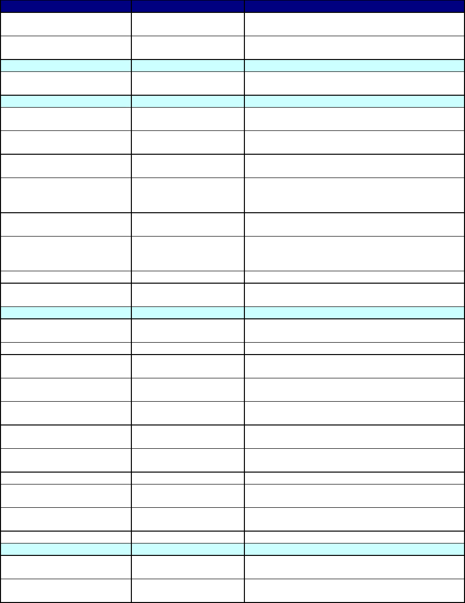
4-22
Data Elements Attributes Definition
performanceStandardText The text that describes the measured criteria of a specific
Occupation.
seriesTypeCode The code that denotes a specialized line of work
associated with a specific Occupation.
OperationalRole
responsibilityText The text that characterizes the chief obligation of a
specific OperationalRole.
Position
durationTypeCode The code that represents a time frame applicable to a
Position.
manningReasonCode The code that represents the underlying basis for the
maintenance of a Position.
mobilizationRequirement
Code
The code that denotes whether a Position is required
during periods of special preparation for contingency.
peacetimeRequirement
Code
The code that denotes whether a Position is required
during times other than periods of special preparation for
contingency.
scheduleTypeCode The code that represents a specific kind of work routine
applicable to a Position.
travelFrequency
RequirementCode
The code that represents the estimated days per month
the incumbent of a Position will need to be away from
home.
typeCode The code that represents a specific kind of Position.
workScheduleQuantity The quantity of work-time commitment established for a
Position.
ProcessActivity*
alternateIdentifierText The text that alternatively identifies a specific
ProcessActivity.
categoryCode* The code that represents the class of a ProcessActivity.
creationCalendarDate The calendar date on which a ProcessActivity was
originated.
dataStoreTypeCode The code that represents a class of ProcessActivity that
is a repository of data.
definitionText The text that unambiguously characterizes a specific
ProcessActivity.
hierarchyDescriptionText The text that characterizes the relationship of a specific
process-activity to other instances of ProcessActivity.
hierarchyName The name that represents the relationship of a specific
process-activity to other instances of ProcessActivity.
scopeText The text that describes the extent of a ProcessActivity.
sourceDocumentText* The text of the origination documentation of a
ProcessActivity.
validationStatusCode The code that represents the state of sanctioning of a
ProcessActivity.
versionIdentifierText The text that identifies a rendition of a ProcessActivity.
Skill
conditionText The text that describes the circumstances of a specific
Skill.
performanceStandardText The text that describes the measured criteria of a specific
Skill.

4-23
Relationships
Parent Verb Phrase Child
Capability
is related to
Capability
Capability
is cited in
Document
Capability
is performed by
Network
Capability
is performed by
System
CapabilityCategory
is the class of
Capability
InformationExchangeRequirement
is specified using
ActivityModelInformationElementRoleIer
InformationExchangeRequirement
is referenced in
InformationExchangeMatrixElement
InformationExchangeRequirement
is restricted by
InformationExchangeRequirementAssurance
InformationExchangeRequirement
may have a
InformationExchangeRequirementElement
InformationExchangeRequirement
risks
InformationExchangeRequirementFailureImpactDetail
InformationExchangeRequirement
is subject to
InformationExchangeRequirementTrigger
InformationExchangeRequirement
is used in
OperationalMissionThreadElement
InformationExchangeRequirement
cites
DiscoveryMetadata
InformationRequirement
is used for
InformationExchangeRequirement
NetworkType
describes
Network
Occupation
may be cited for
OperationalRole
OperationalRole
is represented by
Node
OperationalRole
performs
ProcessActivity
OperationalRole
is performed by
Organization
OperationalRole
is performed by
OrganizationType
Position
may be cited for
OperationalRole
ProcessActivity
is cited for
Architecture
ProcessActivity
is performed at
Node
ProcessActivity
is performed by
OperationalRole
ProcessActivity
is carried out by
Organization
ProcessActivity
is carried out by
OrganizationType
ProcessActivity
is related to
ProcessActivity
ProcessActivity
is cited in
Document
ProcessActivity
corresponds to
Task
ProcessActivity
is assigned to
System
Skill
may be cited for
OperationalRole
Task
is destination
need for
InformationExchangeRequirement
Task
is source of need
for
InformationExchangeRequirement
(All previous relationships for the listed entities that comprise the information space of OV-2 should be considered
part of the specification for this product, as well as those for the entities modeled via ObjectByReference and
ObjectVersionAssociation. For the latter, see Volume III.)
4-24
4.3 OPERATIONAL INFORMATION EXCHANGE MATRIX (OV-3)
4.3.1 OV-3 – Product Description
Product Definition. The OV-3 details information exchanges and identifies “who exchanges
what information, with whom, why the information is necessary, and how the information
exchange must occur.” [CJCSI 6212.01D, 2006] There is not a one-to-one mapping of OV-3
information exchanges to OV-2 needlines; rather, many individual information exchanges may
be associated with one needline.
Product Purpose. Information exchanges express the relationship across the three basic
architecture data elements of an OV (operational activities, operational nodes, and information
flow) with a focus on the specific aspects of the information flow and the information content.
Certain aspects of the information exchange can be crucial to the operational mission and should
be tracked as attributes in OV-3. For example, if the subject architecture concerns tactical
battlefield targeting, then the timeliness of the enemy target information is a significant attribute
of the information exchange.
Product Detailed Description. OV-3 identifies information elements and relevant attributes
of the information exchange, and associates the exchange to the producing and consuming
operational nodes and activities and to the needline that the exchange satisfies.
Information exchange is an act of exchanging information between two distinct operational
nodes and the characteristics of the act, including the information element that needs to be
exchanged and the attributes associated with the information element (e.g., Scope), as well as
attributes associated with the exchange (e.g., Transaction Type). A needline represents one or
more information exchanges.
Information element is a formalized representation of information subject to an operational
process (e.g., the information content that is required to be exchanged between nodes). In
contrast, an information exchange is composed of the needline, the information element, and
other attributes such as Information Assurance attributes. The specific attributes of the
information elements included are dependent on the objectives of the specific architecture effort
and include the information scope, accuracy, and language. An information element may be used
in one or more information exchanges.
The specific mission/scenario and the related task from the UJTL or Mission Essential Task
List (METL) can be noted as an attribute of the information exchange. A mission/scenario may
be selected from the Joint Mission Areas. UJTL and METL tasks are related to a specific
scenario that requires the information.
The emphasis in this product is on the logical and operational characteristics of the
information. It is important to note that OV-3 is not intended to be an exhaustive listing of all the
details contained in every information exchange of every operational node associated with the
architecture in question nor should the production of such a matrix be considered sufficient to
replace an integrated architecture development effort. Rather, this product is intended to capture
the most important aspects of selected information exchanges.

4-25
A partial format for OV-3 matrix can be found in CJCSI 6212.01D, and that format is
required for Information Support Plan (ISP) development. However, additions to the CJCSI
6212.01D matrix to meet program-unique needs should also be allowed. Figure 4-9 shows a
representative format for the OV-3.
Needline
Identifier
Information
Exchange
Identifier
Information Element
Description
Producer Consumer
Information Element
Name and Identifier
Content
Scope
Accuracy
Language
Sending Op Node
Name and Identifier
Sending Op Activity
Name and Identifier
Receiving Op Node
Name and Identifier
Receiving Op Activity
Name and Identifier
Needline
Identifier
Information
Exchange
Identifier
Nature of
Transaction
Performance
Attributes
Information
Assurance
Security
Mission/Scenario
UJTL or METL
Transaction Type
Triggering Event
Interoperability Level
Required
Criticality
Periodicity
Timeliness
Access Control
Availability
Confidentiality
Dissemination Control
Integrity
Accountability
Protection (Type
Name, Duration, Date)
Classification
Classification Caveat
Figure 4-9: Operational Information Exchange Matrix (OV-3) – Template
In Figure 4-9, each information exchange is associated with the needline it helps satisfy.
There may be many individual exchanges that collectively satisfy a single needline. Note also
that each information element exchanged is related to the leaf operational activity (from the OV-
5) that produces or consumes it. However, there may not be a one-to-one correlation between
information elements listed in the matrix and the information inputs and outputs that connect
activities in a related OV-5. Information inputs and outputs between activities performed at the
same node (i.e., not associated with a needline on OV-2) will not show in OV-3. Information
inputs and outputs between activities for some levels of operational activity decomposition may
be at a higher level of abstraction than the information elements in the matrix. In this case,
multiple information exchanges will map to a single operational activity input or output.
Similarly, the information inputs and outputs between activities at a low level of activity
decomposition may be at a higher level of detail than the information exchanges in the matrix,
and multiple information inputs and outputs may map to a single information exchange.
Information elements trace to the entities in a OV-7.
4-26
4.3.2 UML Representation
There is no equivalent diagram to this product in UML. The information exchanges of OV-3
trace to the collaboration or sequence diagram information flows supporting OV-5 and depicted
in OV-2 and OV-6c products.
This product is a detailed table that expands on the information associated with OV-2
operational nodes, OV-5 operational activities, and OV-6 elements. If an automated tool is used
to create the other products in UML, then the OV-3 expanded definitions can be attached to the
applicable elements by using adornments and the documentation facilities possible in the UML
tool. As a result, a script may be developed that will automatically generate the matrix.
4.3.3 Net-Centric Guidance for OV-3
Augmented Product Purpose. In the NCE, the OV-3 captures details that guide the
determination of the specific information that will be obtained or provided in a net-centric
manner.
Net-Centric Product Description. The OV-3 traditionally identifies information elements
and relevant attributes of the information exchange associated with a needline between
producing and consuming operational nodes in the OV-2. In the NCE, additional information
elements and attributes may be included in the matrix to highlight or capture the following:
• The use of an operational profile, which captures COI information, discovery
metadata, and the settings and other data associated with security and access
control, eases the representation of one-to-many, many-to-many, and many-to-
one information exchanges because it associates usage permissions of the
information to an individual user or a group of users in the NCE.
• Provide detailed description of the information exchange from external
providers.
• Identify the intended use (internal use only, external only, or open to internal
and external use).
• Identify the authorized use for information assurance.
In the NCE, services within a program may consume information without always knowing
what the providing service is and/or who the service provider is. The OV-3 may be depicted as
two separate products:
• Information Exchange Provided describes and expands on the information
associated with OV-2 operational nodes that is made available to the NCE,
which includes known as well as those authorized, but beyond the original
predefined set of users
• Information Exchange Consumed describes and expands on the information
associated with OV-2 operational nodes that are required to be obtained from
the NCE, without predetermined knowledge of the producer
In the NCE, analysis of the Service Functionality Providers and Service Consumers (and the
needlines between them in a net-centric OV-2) aides in the identification of specific information
that is produced or consumed within the architecture. The net-centric OV-3 provides the details
of the information exchanged, represented by needlines in the OV-2. The automated information

4-27
exchanges and associated characteristics are captured in the SV-6. The net-centric OV-3
provides guidance for the following efforts:
• Determining, analyzing, and selecting external sources of information
• Initiating negotiations of usage permissions, expectations, and performance
agreements with external organizations responsible for providing or consuming
information
4.3.4 CADM Support for OV-3
Figure 4-10 provides an overview of the CADM data structures related to each
InformationExchangeRequirement and, more generally, to any
InformationTechnologyRequirement. Using these entities, detailed characteristics can be stored
for each IER cited in OV-3.
OV-3 is stored as an instance of Document with its attribute
ArchitectureProductCategoryCode designating it as an
INFORMATION-EXCHANGE-MATRIX. In
CADM v1.5, each row of OV-3 is built by linking in ObjectVersionAssociation, the pertinent
constituents of the matrix, to an instance of ObjectByReference with CategoryCode =
INFORMATION-EXCHANGE-MATRIX-ELEMENT. The OV-3 can in this manner point to:
21
• Instances of CommunicationMedium
• Instances of MaterielType
• Information requirements, exchange needlines, exchange requirements by
activity, and IERs via Guidance
• Message standards via Agreement (usually applies only to SV-6)
• Applicable timeframes via Period (usually applies only to SV-6)
21
This entity has additional attributes used for SV-6 Systems Data Exchange Matrix.

4-28
Figure 4-10: CADM Diagram for OV-3
Using these references, all the attributes of Guidance, Agreement, and their subtypes can be
inserted into OV-3. In addition, these entities can be linked to other entities in CADM v1.5,

4-29
allowing the construction of very rich OV-3 content. The following list shows some of the
additional data that can be made part of a data-centric OV-3:
22
• OrganizationType (e.g., OperationalFacility)
• DataItemType
• Organization
• Task
• InformationElement
• SecurityClassification
The following indicate the ways in which the CADM supports draft IER requirements
provided by the Office of the Joint Staff J6 to the Architecture Framework Working Group in
January 2003:
• Link to OV-2—Number given to each needline in OV-2; supported in CADM
v1.5 via Guideline and its subtypes.
• Rationale/UJTL Number—Set of joint mission tasks from the UJTL (CJCM
3500.04B) for each mission area; supported in CADM v1.5 via Task, which can
be linked to specific InformationExchangeRequirement(s) with specific roles (e.g.,
Source Task, Destination Task) in ObjectVersionAssociation.
• Event—Event that triggers the need for the information exchange; supported in
CADM v1.5 through textual description via the attribute CausalEventTriggerText
in the entity InformationExchangeRequirement; if the trigger is in the form of a
doctrinal rule, CADM v1.5 specifies that kind of trigger as an instance of
OperationalRule, linking it to the InformationExchangeRequirement.
• Information Characterization—Critical information characteristics that describe
what information is being exchanged and how it is to be used; supported in
CADM v1.5 through textual description via the attribute SynopsisText in the
entity Guidance and linking that instance to InformationExchangeMatrix; where
the information is known at a sufficient level of granularity, CADM v1.5
specifies it through the use of the attributes of InformationElement and links the
pertinent instances to InformationRequirement.
• Send Node
—Sending Node; supported in CADM v1.5 through the relationships
that can be established to link instances of OrganizationType with appropriate
roles (e.g., sending) to ExchangeNeedlineRequirement; if the role of send node is
specifically linked to an IER, the sending node may be specified more formally
through the entity Node and then linked to InformationExchangeRequirement.
(Note: In some architectures, the Sending Node represents an OperationalFacility,
which is a subtype of OrganizationType. In network-centric operations, the
Sending Node may represent an information network.)
22
Not shown in this list are all the other data structures that were modeled explicitly in CADM 1.02/1.03 and which are now instantiatable via
ObjectByReference. In addition, please note that references to additional entities are implementation specific and are listed for the Systems
Data Exchange Matrix (SV-6).

4-30
• Receive Node—Receiving Node; supported in CADM v1.5 through the
relationships that can be established to link instances of OrganizationType with
appropriate roles (e.g., receiving) to ExchangeNeedlineRequirement; if the role of
receive node is specifically linked to an IER, the receiving node is specified
more formally through the entity Node and then linked to the instance of
InformationExchangeRequirement. (Note: In some architectures, the Receiving
Node represents an OperationalFacility, which is a subtype of OrganizationType.
In network-centric operations, the Receiving Node may represent an information
network.)
• Critical—Criticality assessment of the information being exchanged in
relationship to the mission; supported in CADM v1.5 through ObjectByReference
with CategoryCode = INFORMATION-EXCHANGE-REQUIREMENT-ASSURANCE.
The attribute InformationCriticalityCode
23
is specified in CADM v1.5 via
ObjectByReferenceCharacterization (see Volume III for details). The (DoD-
approved) values of this code are the following:
− 1 = Category 1 Mission Critical (Force C2)—Critical and high-level
information (e.g., emergency action message and commander’s guidance)
− 2 = Category 2 Mission Critical (Mission Operations)—Required in support
to operations (e.g., joint task force contingency plans and operations plan)
− 3 = Category 3 Mission Critical (Core Functions)—Ongoing information
exchanges (e.g., configuration and guidance information and restricted
frequency list)
− 4 = Mission critical [not otherwise specified]
− 5 = Mission support—Logistics, transportation, medical (e.g., gallons of
petroleum-oil-lubrication scheduled for delivery)
− 6 = Administrative—Personnel, pay, training, etc. (e.g., change in allotment)
• Format—Description of Data Type; supported in CADM v1.5 through instances
of DataItemType linked to InformationExchangeMatrix when the user wishes to
specify its own categorization of the types of data; where the format adheres to a
standard, CADM v1.5 specifies it via MessageStandard and links it to
InformationExchangeMatrix; if the format is specifically related to an information
requirement, CADM v1.5 specifies it via the attribute PhysicalFormatTypeCode
in the entity InformationRequirement.
24
• Interoperability Level Required—Class of technical means intended to be used
for information exchange; supported in CADM v1.5 through the attribute
23
The attribute InformationCriticalityCode is formally defined as “The code that represents the seriousness of the benefit that the information
exchange element provides to the objective of the action being taken for a specific information exchange requirement assurance.” Approved
under DoD 8320.1 procedures as Standard Data Element 63248 (INFORMATION-EXCHANGE-REQUIREMENT-ASSURANCE
INFORMATION CRITICALITY CODE), Version 1, DoD Data Dictionary System, January 2003.
24
Approved domain values include: 01 = Audio; 02 = Text; 03 = Graphic (To Include Facsimile); 04 = Imagery Not Otherwise Specified; 05 =
Imagery, Still; 06 = Imagery, Stop Motion; 07 = Imagery Full Motion; 08 = Data Not Otherwise Specified; 09 = Data, ASCII; 10 = Data, Bit-
Oriented; 11 = Face-To-Face Meeting; 12 = Courier; 13 = Film; 14 = Paper; 15 = Magnetic Tape; 16 = Optical Disk; 17 = Magnetic Disk; 18
= Video (Full-Motion Video With Audio); 19 = Visual Not Otherwise Specified.

4-31
InteroperabilityLevelCode in the entity InformationTechnologyRequirement.
Approved domain values include the following high-level technical means:
− 01 = Level 0—Isolated Level (Manual), without sublevel distinction
− 07 = Level 1—Connected Level (Peer-to-Peer), without sublevel distinction
− 12 = Level 2—Functional Level (Distributed), without sublevel distinction
− 16 = Level 3—Domain Level (Integrated), without sublevel distinction
− 20 = Level 4—Enterprise Level (Universal), without sublevel distinction
• Timeliness—Required maximum time from node to node expressed in seconds;
supported in CADM v1.5 through the attribute TimelinessCode in the entity
InformationTechnologyRequirement.
25
When actual numerical values are known,
CADM v1.5 specifies them through the two attributes FrequencyHighQuantity
and FrequencyLowQuantity in the entity InformationTechnologyRequirement.
• Access Control—Mechanism used to ensure that only authorized users can
access information; supported in CADM v1.5 through ObjectByReference with
CategoryCode = INFORMATION-EXCHANGE-REQUIREMENT-ASSURANCE. The
pertinent attribute, AccessControlTypeCode, is defined in CADM v1.5 via
ObjectByReferenceCharacterization. The approved domain values include the
following:
− 1 = Not Required—No checks of any kind; anybody can access the
information or the information system (e.g., access to most World Wide Web
sites)
− 2 = Profile—Access is controlled by assessing whether the individual seeking
access displays the characteristics typically required (e.g., a carload of
individuals are granted access to a post because they are in uniform and the
car has a sticker)
− 3 = Password and Identification Document—Individual seeking access must
be known and provide a predetermined password (e.g., bank ATMs require
both the user’s card [ID] and the user to enter a personal identification
number [PIN] [password])
− 4 = SSL (Secure Sockets Layer [Server-Based])
− 5 = ID Cert/ACL—An identification certificate and presence of the identified
entity on a valid access control list (ACL)
− 6 = Crypto Ignition Key (CIK)—Key required for secure access (e.g., STU
III)
− 7 = Pairwise Key—Source encrypts the information and the destination
decrypts the information using symmetric keys
• Protect—Mechanism used to ensure that only authorized users can access
information; supported in CADM v1.5 through ObjectByReference with
25
Approved as Standard Data Element 63267, Version 1, DoD Data Dictionary System, January 2003. Domain values include: 1D = Up to One
Day (8 Hour -24 Hours); 1H = Up to One Hour (10 Minutes -1 Hour); 1M = Up to One Month (1 Day -30 Days); 8H = Up to 8 Hours (1
Hour -8 Hours); GM = Greater than One Month; LG = Large (Greater Than 30 Days); M = Moderate (1-10 Seconds); NK = Not Known;
NRT = Near-Real-Time (Less Than 1 Second); NS = Not Specified; RT = Real-Time; S = Slow (10 Seconds -10 Minutes).

4-32
CategoryCode = INFORMATION-EXCHANGE-REQUIREMENT-ASSURANCE. The
pertinent attributes, ProtectionDurationCode, ProtectionElapsedTimeQuantity, and
ProtectionSuspenseCalendarDate, are defined in CADM v1.5 via
ObjectByReferenceCharacterization. The approved domain values include the
following:
− ProtectionDurationCode approved domain values include the following:
a. 1 = None
b. 2 = Encrypted for Transmission Only (EFTO)—After transmission is
completed, information protection is not required
c. 3 = Originating Agency’s Determination Required (OADR)
d. 4 = Specified until explicit expiration date
e. 5 = Specified as end of mission
f. 6 = Specified as a period of time beginning as of the date and time of
transmission and ending after an explicitly provided length of time
• Classification—Classification of the information; supported in CADM v1.5
through instances of SecurityClassification, which can be linked to
InformationExchangeRequirement.
• Block Increment—Designated block or increment of the IER is required (usually
by separate timeframes); supported in CADM v1.5 through the attribute
BlockName in the entity InformationTechnologyRequirement.
4.3.4.1 OV-3 - Data Element Definitions
OV-3 Information Space
Architecture
†
Capability
†
CapabilityCategory
†
Document
†
ExchangeNeedLineRequirement
†
Guidance
†
InformationElement
†
InformationExchangeRequirement
†
InformationRequirement
†
InformationTechnologyRequirement
†
Node
†
Organization
†
OrganizationType
†
ProcessActivity
†
SoaService
†
System
†
Task
†
CommunicationMedium
DataItemType
DiscoveryMetadata
†)
The descriptions of these elements have been provided in the preceding sections
Table 4-3: Data Element Definitions for OV-3
26
Data Elements Attributes Definition
CommunicationMedium
categoryCode The code that represents a class of
CommunicationMedium.
typeName The name of the general class to which a specific
CommunicationMedium belongs.
26
As noted earlier, data elements marked with an asterisk (*) should be included by the architecture development team, if the product is chosen
for development as part of an integrated architecture effort.

4-33
Data Elements Attributes Definition
DataItemType
approvalStatusCode The code that denotes the state of validity for the data for a
DataItemType.
detailCode The code that represents on a detailed level a
DataItemType. source: c4rdp, information-exchange-term
code--the code, expressed as 4 characters, that represents
the information exchange term.
groupingClassCode The code that represents a specific grouping of a
DataItemType.
typeCode The code that represents a kind of DataItemType.
DiscoveryMetadata
commentText The text that explains the specialized character of a specific
instance of DiscoveryMetadata.
definitionText The text that unambiguously characterizes an instance of
DiscoveryMetadata.
lastModification
CalendarDatetime
The calendar date-time at which a specific instance of
DiscoveryMetadata was most recently changed.
obligationLevelText The name that indicates the degree to which an instance of
DiscoveryMetadata is required to be supplied.
primaryCategoryName The name of the major class to which a specific instance of
DiscoveryMetadata belongs.
referencedSourceName The name that provides a source for a specific instance of
DiscoveryMetadata.
setName The name of the high-level function focus of an instance of
DiscoveryMetadata.
subcategoryName The name of a specific type of DiscoveryMetadata.
Relationships
Parent Verb Phrase Child
CommunicationMedium
is used to transport
InformationExchangeRequirement
ConceptualDataModel
cites
DiscoveryMetadata
DataItemType
uses
InformationRequirement
InformationExchangeRequirement
cites
DiscoveryMetadata
InformationTechnologyRequirement
cites
CommunicationMedium
Node
uses
CommunicationMedium
(All previous relationships for the listed entities which comprise the information space of OV-3 should be considered
part of the specification for this product, as well as those for the entities modeled via ObjectByReference and
ObjectVersionAssociation. For the latter see Volume III.)
4-34
4.4 ORGANIZATIONAL RELATIONSHIPS CHART (OV-4)
4.4.1 OV-4 – Product Description
Product Definition. The OV-4 illustrates the command structure or relationships (as
opposed to relationships with respect to a business process flow) among human roles,
organizations, or organization types that are the key players in an architecture.
Product Purpose. This product clarifies the various relationships that can exist between
organizations and sub-organizations within the architecture and between internal and external
organizations.
Product Detailed Description. OV-4 illustrates the relationships among organizations or
resources in an architecture. These relationships can include supervisory reporting, command
and control relationships, and command-subordinate relationships. Another type of relationship
is a coordination relationship between equals, where two organizations coordinate or collaborate
without one having a supervisory or command relationship over the other. Others may be defined
depending on the purpose of the architecture. Architects should feel free to define any kinds of
relationships necessary and important within their architecture to support the goals of the
architecture. For example, dynamic teams or task forces (i.e., new operational nodes) may be
created in real time with only limited lifespans and assigned missions, and could have needlines
assigned to them. The creating node and the created node have a unique relationship that should
be documented. This relationship may not be one of lines of command or organizational
hierarchies, as these do not necessarily map to the needlines of OV-2. In this product, the
dynamic organizations represented by operational nodes in OV-2 have a limited lifespan and a
temporary collaboration relationship.
The product illustrates the relationships among organizations or organization types that are
the key players in an architecture. These key players correspond to the operational nodes of an
OV-2, which contains added detail on how the key players interact together in order to conduct
their corresponding operational activities of OV-5.
Human roles whose skills are needed to perform the operational activities or business
processes described in the architecture may also be defined in OV-4. The corresponding
operational activities should be decomposed to a degree that allows them to be correlated to
specific human roles within organizations. In the case of target architectures, human roles that do
not reflect a specific supervisory reporting, command and control, or coordination organizational
structure may be used in OV-4. In this case, OV-4 may be developed using strictly human roles
that are the key players in an architecture.
Organizational relationships are important to depict in an OV (for a current architecture),
because they can illustrate fundamental human roles (e.g., who or what type of skill is needed to
conduct operational activities) as well as management relationships (e.g., command structure or
relationship to other key players). Organizational relationships may influence how the
operational nodes in an OV-2 are connected. A template is shown in Figure 4-11.
As the template illustrates, boxes can show hierarchies of organizations, and different colors
or styles of connecting lines can indicate various types of relationships among the organizations.
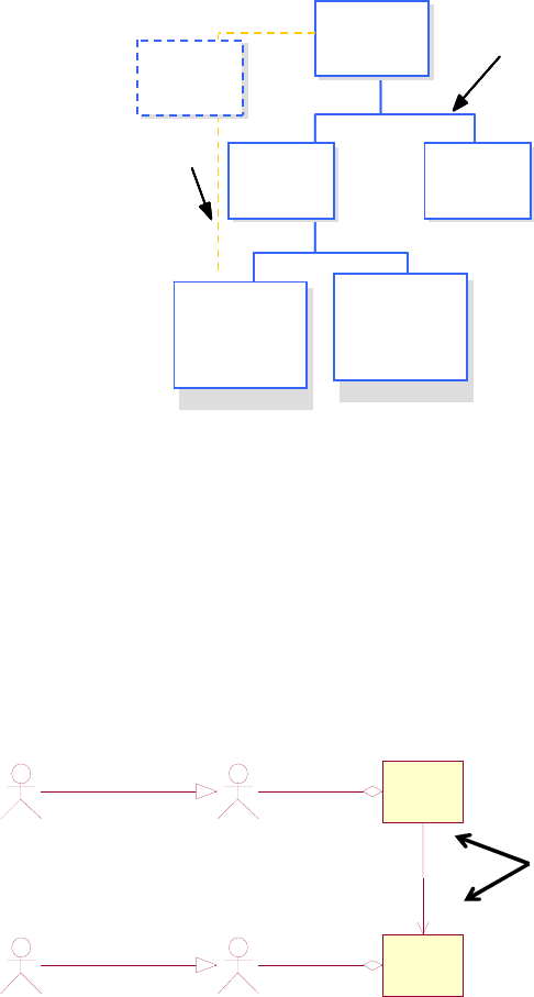
4-35
Top-Level
Organization
Command
Relationship
Second-
Level
Organization
Second-
Level
Organization
Third-
Level
Organization/
Human Role
Coordination or
Other Specified
Relationship
Working
Group
Third-
Level
Organization/
Human Role
Top-Level
Organization
Top-Level
Organization
Command
Relationship
Command
Relationship
Second-
Level
Organization
Second-
Level
Organization
Second-
Level
Organization
Second-
Level
Organization
Third-
Level
Organization/
Human Role
Coordination or
Other Specified
Relationship
Working
Group
Third-
Level
Organization/
Human Role
Figure 4-11: OV-4 – Template
4.4.2 UML Representation
A UML class diagram best represents the OV-4. The DoDAF architect uses operational node
stereotyped classes on these diagrams along with their UML association (i.e., bi-directional,
unidirectional, aggregation, composition, or generalization). Figure 4-12 below presents a
simple example of a UML OV-4. Some DoDAF UML architects prefer to aggregate operational
nodes or play relationships to actors on the use case diagram; alternately, the OV-4 class diagram
can accomplish these relationships as well. Most UML tools recognize the association
relationship irrespective of their creation point in the model.
Role 1
Role 2
Node A
<<onode>>
Node B
<<onode>>
1..n
1
Intelligence
Watch Officer
Mission Planner
<<plays>>
<<plays>>
1
1..n
commands
This reads that
This reads that
there is at least
there is at least
one Node A that
one Node A that
commands one to
commands one to
many Node B
many Node B
Figure 4-12: UML OV-4 Sample
4.4.3 Net-Centric Guidance for OV-4
Augmented Product Purpose. In a net-centric architecture, the OV-4 depicts the Service
Functionality Providers and Service Consumers and provides a description of their associated
operational roles in support of net-centric information sharing.
Net-Centric Detailed Description. The OV-4 traditionally illustrates the relationships
among organizations or resources depicted within an architecture. Accordingly, describing the
NCE within an architecture, the OV-4 should define any kinds of relationships necessary to
support NCO with respect to populating and using the NCE to achieve the goals of the mission
4-36
outlined in the OV-1. In the NCE, the OV-4 identifies the organizations that can be given an
operational role of service functionality provider or service consumer on the OV-2.
As programs begin to architect for the NCE, the OV-4 may accommodate organizational
relationships that depict the collaborative nature required to execute NCO. The current
hierarchical depiction of the OV-4 may be tailored to show how organizations work more jointly
to develop capabilities and share information on the GIG.
An OV-4 diagram may be used to depict the organizational relationships of COIs who
participate in defining vocabularies, taxonomies, and information exchange agreements in
pursuit of shared goals, interests, missions, or business processes. As mentioned in Section 2.5,
Net-Centric Guidance for Architecture Products, by identifying the COIs supported by various
programs, the architecture may be used to depict information sharing agreements that are used
across architectures, and accordingly, enabling more seamless information sharing in the NCE.
The net-centric OV-4 may be used to:
• Represent the structure and governance of users that support data sharing
agreements used within the architecture.
• Describe COI structures and highlight how/where organization supports the
COI or how the COI's guide/influence the organization in a separate OV-4.
• Depict the COI governance in terms of organizations, programs, and
stakeholders who are part of the COI and participate in developing, managing,
and adjudicating the COI standards and agreements.
Documenting these relationships in a net-centric relationship will provide an understanding
of the relationships among internal and external organizations, classes of users, operational
profiles, and operational roles that are key players in the architecture.
4.4.4 CADM Support for OV-4
Each OV-4 is represented in CADM v1.5 as an instance of Document with
ArchitectureProductCategoryCode = ORGANIZATIONAL-RELATIONSHIP-CHART. The key entities
used to specify the architecture data in OV-4 are presented in Figure 4-13, a high-level
diagram from the CADM showing key entities that are used to store architecture data for OV-4
in a CADM-conformant database.

4-37
Figure 4-13: CADM Diagram for OV-4
In CADM v1.5, the content of an OV-4 is built via Node. An instance of Organization or of
OrganizationType can be linked to an instance of Node. Once this is done, hierarchically related
pairs of nodes can be expressed via ObjectVersionAssociation and the specific node pairs can be
linked to the OV-4 (see Volume III for details). Icons can be specified as instances of
IconCatalog and linked to the pertinent instances of either OrganizationType or Organization to
enforce, for example, consistent graphical representations of OrganizationType(s) or
Organization(s) in an architecture.

4-38
4.4.4.1 OV-4 – Data Element Definitions
OV-4 Information Space
Architecture
†
Document
†
Node
†
OperationalRole
†
Organization
†
OrganizationType
†
ProcessActivity
†
SoaService
†
IconCatalog
OperationalElement
OperationalFacility
†)
The descriptions of these elements have been provided in the preceding sections
Table 4-4 describes the architecture data elements for OV-4.
Table 4-4 Data Element Definitions for OV-4
Data Elements Attributes Definition
IconCatalog
defaultReferenceName The name of an instance of IconCatalog catalog that is used
by the application for internal citations.
iconTypeCode The code that represents a kind of IconCatalog.
linkArrowstyleTypeCode The code that represents the kind of arrowhead that will
appear on the end(s) of a link type IconCatalog instance.
linkColorIdentification
Text
The text that identifies the color to be depicted for a specific
link type IconCatalog instance.
linkLinePoint
CharacteristicCode
The code that represents the thickness of a link type
IconCatalog instance. Default value is "8" (1-point solid line).
linkLinetypeTypeCode The code that represents the kind of segmentation to be
used for a link type IconCatalog instance. Default value is
"1."
nodeCategoryCode The code that represents the kind of IconCatalog that
represents a node type IconCatalog instance.
nodeSubcategoryCode The code that represents a detailed classification of
IconCatalog instances that represent a node.
OperationalElement
approvalStatusCode The code that represents the state of validity for the data for
an OperationalElement.
categoryCode The code that represents a class of OperationalElement.
useTypeCode The code that represents a kind of OperationalElement by
intended employment.
OperationalFacility
alternateIdentifierText The text that describes the identifier that acts as a substitute
for identifying an OperationalFacility.
approvalStatusCode The code that represents the state of validity for the data for
an OperationalFacility.
historicalJustification
Text
The text of the rationale for the application of an
OperationalFacility.
iterationIdentifierText The text which describes the identifier that distinguishes the
OperationalFacility from any other OperationalFacility with
the same echelon and proponent.
justificationText The text of the rationale for the application of an
OperationalFacility.
remarkText The text representing the comments regarding a specific
OperationalFacility.
titleName The name representing the label to be used for a specific

4-39
Data Elements Attributes Definition
OperationalFacility.
Relationships
Parent Verb Phrase Child
IconCatalog
is related to
IconCatalog
OperationalElement
describes type of
OperationalFacility
(All previous relationships for the listed entities that comprise the information space of OV-4 should be considered
part of the specification for this product, as well as those for the entities modeled via ObjectByReference and
ObjectVersionAssociation. For the latter, see Volume III.)
4-40
4.5 OPERATIONAL ACTIVITY MODEL (OV-5)
4.5.1 OV-5 – Product Description
Product Definition. The OV-5 describes the operations that are normally conducted in the
course of achieving a mission or a business capability. It describes capabilities, operational
activities (or tasks), input and output (I/O) flows between activities, and I/O flows to/from
activities that are outside the scope of the architecture. High-level operational activities should
trace to (and are decompositions of) a Business Area, an Internal Line of Business, and/or a
Business Sub-Function as published in OMB’s Business Reference Model [OMB, 2003].
Product Purpose. OV-5 can be used to:
• Clearly delineate lines of responsibility for activities when coupled with OV-2.
• Uncover unnecessary operational activity redundancy.
• Make decisions about streamlining, combining, or omitting activities.
• Define or flag issues, opportunities, or operational activities and their
interactions (information flows among the activities) that need to be scrutinized
further.
• Provide a necessary foundation for depicting activity sequencing and timing in
OV-6a, OV-6b, and OV-6c.
• Identify critical mission threads and operational information exchanges by
annotating which activities are critical (i.e., identify the activities in the model
that are critical).
Product Detailed Description. OV-5 describes capabilities, operational activities (or tasks),
I/O flows between activities, and I/O flows to/from activities that are outside the scope of the
architecture.
I/Os of operational activities relate to information elements of OV-3 and are further
characterized by the information exchange attributes described in OV-3. I/Os that are produced
or consumed by leaf operational activities that cross operational node boundaries are carried by
needlines of OV-2. Operational activities can be annotated (e.g., via the mechanism arrow in an
IDEF0 diagram) with the corresponding operational node from OV-2.
Annotations to the activities may also identify the costs (actual or estimated) associated with
performing each activity. The business rules that govern the performance of the activities can
also be keyed to each activity. (Business rules are described in OV-6a.) Annotations to OV-5s
can further the purposes of the description by adding specific attributes of exchanged
information, which can later be used in OV-3.
OV-5 is a key product for describing capabilities and relating capabilities to mission
accomplishment. The DoD Dictionary of Military Terms [DoD JP 1-02, 2001] defines a
capability as “the ability to execute a specified course of action. (A capability may or may not be
accompanied by an intention.)” A capability can be defined by one or more sequences of
activities, referred to as operational threads or scenarios. A capability may be further described in
terms of the attributes required to accomplish the set of activities (such as the sequence and
timing of operational activities or materiel that enable the capability), in order to achieve a given
4-41
mission objective. Capability-related attributes may be associated with specific activities or with
the information flow between activities, or both. When represented by a set of operational
activities, a capability can also be linked to an operational node in an OV-2.
Integrated architectures with Doctrine, Organization, Training, Materiel, Leadership &
education, Personnel, and Facilities (DOTMLPF) information provide a structured and organized
approach for defining capabilities and understanding the underlying requirements for achieving
those capabilities. The full spectrum of DOTMLPF is modeled and related so that analyses and
decisions can be supported by describing the sequence and timing of activities; tying them to the
operational nodes (representing organizations or human roles); relating them to their supporting
systems or system functions; and specifying the actions, events, and related guard conditions or
business rules that constrain those activities. Below is a detailed description of how DOTMLPF
is tightly weaved into this and related products.
• Doctrine may influence controls or guard conditions in OV-5.
• Organization is represented via the operational nodes of OV-2, which can be
shown as mechanisms (or annotations to the activities) in OV-5.
• Training is represented via the operational node that may represent a human
role, which, in turn, embodies a certain skill set or knowledge domain required
to perform the activities that are, in turn, related to operational activities of
OV-5.
• Materiel is tied to the elements in OV-5, where mechanisms may be used to
represent systems that support operational activities. Further materiel detail may
be related to the activities via SV-5, by relating those activities to the system
functions that are executed by systems that automate them (wholly or partially).
Each operational thread or scenario (represented by an OV-6c) is associated
with a certain capability, since a capability is defined in terms of the activities
and their attributes depicted in OV-6c. Consequently, an SV-5 may also be used
to relate a capability to the systems that support it, by labeling a set of activities
with its associated capability (defined in OV-6c), and by labeling the system
functions with the systems that execute them (defined in SV-1, SV-2, and SV-
4).
• Leadership may be represented indirectly in OV-5 by first mapping activities to
operational nodes via mechanisms and through the relationships of an
operational node in OV-2 to organizations, organization types, or leadership
human roles in OV-4.
• Personnel may be represented indirectly through the relationships of an
operational node in OV-2 to organizations, organization types, or human roles
in OV-4.
• Facility is tied to OV-5, because an operational node is directly tied to the
systems nodes (facilities) that house the systems, which may be shown as
mechanisms that support operational activities.
OV-5 graphic(s) may include a hierarchy chart of the activities covered in the model. A
hierarchy chart helps provide an overall picture of the activities involved and a quick reference
for navigating the OV-5 I/O flow model.

4-42
OV-5 is frequently used in conjunction with a process flow model (such as an IDEF3 model,
or a UML sequence diagram) that describes the sequence and other attributes (e.g., timing) of the
activities. A process flow model further captures precedence and causality relations between
situations and events by providing a structured method for expressing knowledge about how a
process or organization works. A process flow model may be annotated with the names of the
operational nodes responsible for conducting those activities. A process flow model may be
described in OV-6c.
The decomposition levels and the amount of detail shown on OV-5 should be aligned with
the operational nodes that are responsible for conducting the operational activities (shown on
corresponding OV-2 products). It is important to note the OV-5 is intended to be only as
exhaustive as necessary to attain the objectives for the architecture as stated in AV-1. Figure
4-14 depicts templates for the Operational Activity Hierarchy Chart and one level of a process-
flow OV-5.
Level 1 Flow Diagram For
Operational Activity (A0)
Flow 1
Flow 2
Flow 3
Flow 4
A1
Activity 1
A2
Activity 2
A3
Activity 3
A1
Activity 1
A2
Activity 2
A3
Activity 3
A1.2
Activity 5
A3.1
Activity 6
A3.2
Activity 7
A1.1
Activity 4
A3.2.1
Activity 8
A3.2.2
Activity 9
A0
High-Level Operational Activity
Activity
Hierarchy
Level 1 Flow Diagram For
Operational Activity (A0)
Flow 1
Flow 2
Flow 3
Flow 4
A1
Activity 1
A2
Activity 2
A3
Activity 3
Level 1 Flow Diagram For
Operational Activity (A0)
Flow 1
Flow 2
Flow 3
Flow 4
A1
Activity 1
A2
Activity 2
A3
Activity 3
A1
Activity 1
A2
Activity 2
A3
Activity 3
A1.2
Activity 5
A3.1
Activity 6
A3.2
Activity 7
A1.1
Activity 4
A3.2.1
Activity 8
A3.2.2
Activity 9
A0
High-Level Operational Activity
Activity
Hierarchy
A1
Activity 1
A2
Activity 2
A3
Activity 3
A1.2
Activity 5
A3.1
Activity 6
A3.2
Activity 7
A1.1
Activity 4
A3.2.1
Activity 8
A3.2.2
Activity 9
A0
High-Level Operational Activity
Activity
Hierarchy
Figure 4-14: Operational Activity Hierarchy Chart and Operational
Activity Diagram (OV-5) – Templates
Figure 4-15 is a process-oriented OV-5 template showing how some additional architecture
data could be added as annotations to the original template. For example, activities may be
annotated with information concerning the operational nodes that conduct them, the materiel that
supports them, the cost of conducting the activity, and so forth. (The types of additional
architecture data are notional.)

4-43
$
Node A
Node B
Node A
Node B
Node A
Node C
Node A
Node C
Node DNode D
$
$
A3
Activity 3
A1
Activity 1
Flow 1
A2
Activity 2
Flow 2
Flow 3
Flow 4
Figure 4-15: OV-5 – Template with Notional Annotations
4.5.2 UML Representation
The UML version of an OV-5 is much different from the IDEF implementation (Figure
4-16). The UML OV-5 presents multiple abstractions, each with more detail. The use case
diagram represents OV-5 from a scope perspective. The use case diagram provides a visual
means to establish the scope (observable result of value) with the stakeholder and the relevant
net-centric interfaces that collaborate with the process. These actor interfaces are potentially
operator interfaces or system interfaces – sometimes an actor can represent both depending on
the level of abstraction modeled. The activity diagram provides the business rules and flow of
control for each instance of the use case. A use case instance is a specific "end-to-end" concrete
path through a use case, specific values, and responses; only a single path through one or more
possible flows of the use case are given. This concept is important to understand when
developing OV-6c, because diagramming instance establishment is important to communicate a
specific thread through a use case. Finally, the activities on the activity diagram each have their
perspective sequence diagram.

4-44
Determine Mission
Processing Needs
Present Alerts and
Notifications
[ alert not requi red ]
[ message not required ]
[ alert required ]
[ message distribution required ]
: ObjectUpdate
<<trigger>>
stored :
ObjectUpdate
: CombatPower
: Alert
: DisseminationRule
: AlertEstablishment
: TrackedTypeList
Information Source
Information
Recipient
Process Mission Updates
CombatPower
: Information
Source
: Information
Source
: DDS : DDS
1: update object item (ObjectUpdate)
2: update object item (ObjectUpdate)
4: determine dissemination needs (ObjectUpdate)
3: determine alerts (ObjectUpdate)
: Information
Recipient
: Information
Recipient
: DDS : DDS
1: present alerts and notifiactions (Alert, CombatPower)
Activity Diagram
Activity Diagram
Use Case Diagram
Use Case Diagram
Sequence Diagram
Sequence Diagram
Sequence Diagram
Sequence Diagram
Determine Mission Processing Needs
Present Alerts and Notifications
Figure 4-16: UML Example OV-5
When modeling UML business use cases (operational view) the architect should render the
system as a black box with the overall system name. When this is the modeling approach, the
architect should not use swimlanes on activity diagrams. This is an important concept to
understand, because the activity is a shared collaboration between the interfaces and the system.
Alternately, the DoDAF architect may wish to develop activity models using swimlanes to
understand and vet through stakeholders the business process to determine automation
opportunities. These “business” activity diagrams are useful in identifying use cases to model
system behavior (net-centric service responsibility). Activity diagrams using systems as
swimlanes may be useful for system design and implementation. The sequence diagram is the
most important view from a net-centric viewpoint, because these diagrams establish service
responsibility. Service responsibilities (UML messages on sequence diagrams) identify external
and internal interface dependencies of the evolving system. The DoDAF architect places
emphasis on the sequence diagram as they provide visibility into patterns of behavior depicted as
activities on the activity diagram.
4.5.3 Net-Centric Guidance for OV-5
Augmented Product Purpose. In the NCE, the OV-5 describes operations, identifies
activities, and may capture the inputs and outputs between nodes that enable programs to operate
in a net-centric manner.
Net-Centric Product Description. The OV-5 traditionally describes capabilities, operational
activities (or tasks), and information flows between internal and external activities. Accordingly,
in the NCE, the OV-5 should capture the capabilities, activities, and information flows for
4-45
posting information and data as soon as possible to encourage discovery and multiple uses as
described in the net-centric OV-2. The net-centric OV-5 may highlight multiple inputs and
outputs from a particular activity to depict the posting of information in various states of
processing (raw, pre-processed, fused, etc). The various states of processing should be readily
identified by analyzing key events within the involved processes that change the state of critical
information objects.
A central tenet of the NCE is that information and capabilities are obtained from, and
contributed to, the netted environment. In operational terms, it is important to identify external
sources that may provide information or capabilities within the architecture, so that its mission is
more effectively executed. It is also equally as important to make capabilities available to
external sources so that they, in turn, may more effectively complete their missions.
Accordingly, the net-centric OV-5 places special significance on the I/O flows between activities
internal to the architecture and those activities external to the architecture. It highlights both
internal activities where information is made available to external activities, and internal
activities which result in information being consumed from external activities.
The net-centric OV-5 may be used in the following ways:
• Delineate lines of dependency on external activities when coupled with OV-2.
• Highlight information flows to depict the status of the information's refinement
(raw, pre-processed, fused, etc.).
• Provide the critical foundation for depicting Task, Post, Process, and Use
(TPPU) activity sequencing and timing in the OV-6a, OV-6b, and OV-6c.
• Identify critical mission threads and operational information exchanges by
annotating which activities are critical, i.e., identify the activities in the model
that are critical.
The decomposition levels and the amount of detail shown on the OV-5 should be aligned
with the operational nodes that are responsible for conducting the operational activities (shown
on corresponding OV-2 products). It is important to note that OV-5 is intended to be only as
exhaustive as necessary to attain the objectives for the architecture as stated in AV-1.
4.5.4 CADM Support for OV-5
Each OV-5 is stored as an instance of Document with its attribute
ArchitectureProductCategoryCode =
ACTIVITY-MODEL-SPECIFICATION. The structure and content
specification of the activity model is stored as an instance of InformationAsset with its attribute
TypeCode = ACTIVITY-MODEL.
An OV-5 can, in principle, apply to many architectures. All the Architecture instances to
which that instance of Document can be linked, are done via ObjectVersionAssociation.
As depicted in Figure 4-17, each activity and subactivity cited in the OV-5 is stored as an
instance of ProcessActivity, and its occurrence in the activity model is captured in CADM v1.5
through the corresponding entry in ObjectVersionAssociation
. Similarly, the specific hierarchical
breakdown of the activities in a given OV-5 is expressed by the appropriate entries in

4-46
ObjectVersionAssociation.
27
Note that different activity models can depict different hierarchical
breakdowns of the same activities; thus, the direct associations among instances of
ProcessActivity are not used for this purpose. Where applicable, instances of Capability can be
linked to the desired instances of ProcessActivity and used to document specific capabilities
underlying an operational activity.
The information flows and their component information flows cited in the OV-5 are stored in
CADM v1.5 as instances of InformationElement, and their occurrences in the activity model are
linked to the OV-5 through ActivityModelInformationElementRole. The decomposition of an
InformationElement into its components is specified by relating the instances in
ObjectVersionAssociation. (Note that in CADM v1.5, such decompositions are not necessarily
dependent on any activity model or operational activity within the OV-5. Therefore, when
capturing this type of information for use in more than one OV-5, one should ensure that it is
consistent across all of them.)
Each InformationElement may occur in an IDEF0 activity model for a specific activity with
four roles: input, control, output, and mechanism. CADM v1.5 specifies this via the entity
ActivityModelInformationElementRole. Note that these roles are for the use of the
InformationElement in relation to a specific OV-5 and do not depend semantically from the
InformationElement itself.
28
The four roles are specified through the attribute CategoryCode in the
entity ActivityModelInformationElementRole.
27
In CADM the Node Tree Diagram from IDEF0, which graphically depicts the activity hierarchy in a specific activity model is specified as an
instance of Document with its attribute ArchitectureProductTypeCode = NODE-TREE, and its contents specified via associations of Node
implemented through ObjectVersionAssociation. By linking each Node in the hierarchical nodal decomposition to a specific instance of
ProcessActivity it is possible to capture the content of the Node Tree Diagram.
28
It is for this reason that the DoD data standard for the entity listing information flows, formerly ICOM, has been changed to be
InformationElement. The new name (ActivityModelInformationElementRole) for the entity ACTIVITY-ICOM has also been approved as a
change to the DoD data standards.

4-47
Figure 4-17: CADM Diagram for OV-5
Mechanisms can be very important for characterizing how elements of an activity model are,
or are to be, supported in carrying out the underlying requirement. In general, mechanisms can
include organizations, classes of organizations, systems, classes of materiel, persons with
specific skills, and facilities. However, OV-5 focuses on requirements and therefore may
intentionally omit references to materiel types, systems, and facilities. The (optional) linkage of
those instances that are conceptualized as mechanisms for an OV-5 in CADM can be expressed

4-48
by the appropriate entries in ObjectVersionAssociation (see Volume III for details). In CADM
v1.5, it is possible to assign instances of the following entities as the mechanisms in an OV-5:
• Organization
• OrganizationType
• OperationalRole
• MaterielType
• System
• Facility
• FacilityType
It is optional to incorporate some or all of the details of an activity model into a CADM-
structured database. At a minimum, both InformationElement and ProcessActivity should be
populated, so that the information flows and operational activities required for OV-3 and SV-5,
respectively, are available for cross reference. Note that in CADM v1.5, system functions are
specifically viewed as a subtype of ProcessActivity. This allows the cross reference of instances
of system functions to other instances of ProcessActivity (i.e., operational activities or other
system functions) through ObjectVersionAssociation. Note also that depending on the level of
granularity specified, system functions may map to single SOA services.
A key element of operational requirement traceability is the relation of instances of
ProcessActivity to Task instances such as those included in (a) UJTL [CJCSM 3500.04C, 2002],
(b) the UJTL extensions for tactical tasks, and (c) the mission essential tasks. In CADM v1.5,
this traceability is supported by establishing the appropriate links between ProcessActivity(s) and
Task(s) through ObjectVersionAssociation. The same approach is used in CADM v1.5 to relate
Document(s) cited for details of an OV-5 (or other subtypes of InformationAsset) to instances of
InformationAsset.
4.5.4.1 OV-5 – Data Element Definitions
OV-5 Information Space
Agreement
†
Architecture
†
Capability
†
DefenseOccupationalSpecialtyCrossReference
†
Document
†
InformationAsset
†
InformationElement
†
Occupation
†
OperationalRole
†
Organization
†
OrganizationType
†
ProcessActivity
†
Skill
†
SoaService
†
System
†
Task
†
ActivityModel
ActivityModelInformationElementRole
Facility
FacilityType
HumanBehaviorTask
LineOfBusiness
MaterielType
ReferenceModel
†)
The descriptions of these elements have been provided in the preceding sections
Table 4-5 describes the architecture data elements for OV-5.

4-49
Table 4-5: Data Element Definitions for OV-5
29
Data Elements Attributes Definition
ActivityModel*
authorName* The name of the architect of an ActivityModel.
calendarDate The calendar date of an ActivityModel.
developmentStatusText The text describing an ActivityModel development state.
organizationContextText The text describing the relationship of an organization with
an ActivityModel.
scopeText* The text that describes the extent of an ActivityModel.
tenseCode The code that represents the time distinction of an
ActivityModel.
typeCode The code that represents a kind of ActivityModel.
validationStatusCode* The code that represents the state of sanctioning of an
ActivityModel.
viewpointText The text that describes the point of view of an
ActivityModel.
ActivityModel
InformationElement
Role*
actualOccurrenceQuantity The existent quantity of an
ActivityModelInformationElementRole.
alternateIdentifierText* The text that alternatively identifies a specific
ActivityModelInformationElementRole.
categoryCode The code that represents a kind of
ActivityModelInformationElementRole.
subcategoryCode The code that represents the detailed class of a specific
ActivityModelInformationElementRole.
externalCode* The code that represents whether a specific
ActivityModelInformationElementRole represents an
external information flow.
mechanismMeansCode The code that represents the specific technique of
employment for an
ActivityModelInformationElementRole.
modificationCalendarDate The calendar date on which a specific
ActivityModelInformationElementRole was last changed.
outputPerformance
MeasureIdentifierText
The text that identifies the information-producing
performance measure of an
ActivityModelInformationElementRole.
outputPerformance
MeasureValueIdentifier
Text
The text that identifies the quantity of a product produced
by a specific ActivityModelInformationElementRole.
unitCostAmount The amount of a single unit cost of an
ActivityModelInformationElementRole.
Facility
alternateIdentification
SourceName
The name of the source of the surrogate identifier of a
Facility.
alternateIdentifierText The text that identifies the surrogate identifier for a Facility.
availableElectricalPower
Quantity
The quantity that represents the maximum rating of the
power panel for the Facility.
constructionBegin The calendar date the building of a Facility commences.
29
As noted earlier, data elements marked with an asterisk (*) should be included by the architecture development team, if the product is chosen
for development as part of an integrated architecture effort.

4-50
Data Elements Attributes Definition
CalendarDate
constructionEnd
CalendarDate
The calendar date the building of a Facility ceases.
constructionPermanency
CategoryCode
The code that represents a class of expected lifetime of a
specific Facility.
electricalServiceCapacity
Rate
The rate of the maximum amount of electrical service to a
Facility.
elevationAboveSeaLevel
Dimension
The dimension elevation from the ground floor of the
Facility to mean sea level.
floorQuantity The quantity of floors in a Facility.
grossArea The area of the available surface for a specific Facility.
identificationLabelText The text that identifies the number of a specific Facility.
lengthDimension The dimension length of a Facility.
peakUsageElectrical
PowerQuantity
The quantity that represents the electrical power demanded
when all the electrical items are operating in a specific
Facility.
telecommunicationDrop
Quantity
The quantity that represents the estimated number of user
telecommunication access point within a specific Facility.
totalFloorSpaceArea The total area of floor space in the Facility.
useCategoryCode The code that represents a kind of Facility.
useSubcategoryCode The code that represents a kind of Facility.
widthDimension The dimension width of a Facility.
FacilityType
classCode The code that represents a class of FacilityType.
useCode The code that represents a specific type of employment of
a FacilityType.
HumanBehaviorTask
activityClassCode The code that represents the type of action represented by
a specific HumanBehaviorTask.
definitionText The text that states the meaning for a specific
HumanBehaviorTask.
hierarchyIdentifierText The text that identifies the relation of a specific
HumanBehaviorTask to other instances of
HumanBehaviorTask.
processCode The code that represents the type of human sensing used
for a HumanBehaviorTask.
LineOfBusiness
businessAreaCode The code that represents a specific kind of services for a
specific LineOfBusiness.
typeCode The code that represents the kind of a specific
LineOfBusiness.
MaterielType
alternateIdentifierText The text that describes the identifier alternatively used to
identify a specific MaterielType.
alternateIdentifierSource
Name
The name of the originator of the MaterielType alternate
identifier.
alternateName The name alternatively used to designate a specific
MaterielType.
approvalStatusCode The code that represents the state of validity for the data for
a MaterielType.
controlNumberType
Code
The code that represents a MaterielType control number.
essentialityCode The code that represents the degree to which the failure of

4-51
Data Elements Attributes Definition
a part affects the ability of the end item MaterielType to
perform its intended operation.
estimatedLowestCost
Amount
The amount representing the smallest projected price of a
specific MaterielType.
federalSupplySchedule
IdentifierText
The text that identifies the specific general service agency
schedule on which the MaterielType appears.
lineItemNumberIdentifier
Text
The text that identifies the alphanumeric string for a specific
MaterielType use, as denoted by the line item number
(LIN).
nomenclatureName The name providing the complete entry for the DoD
standard military naming system for a specific
MaterielType.
productionLeadtime
DaysQuantity
The quantity of days that the manufacturer needs to
manufacture and deliver a MaterielType.
referenceNumber
IdentifierText
The text that identifies the alpha numeric string that relates
the MaterielType to the manufacturer's stock identity.
remarkText The text that provides supplementary information about a
MaterielType.
requirementCode The code that represents whether a specific MaterielType
should be referenced in an
InformationExchangeRequirement.
softwareCode The code that represents whether the MaterielType has
software characteristics.
stockNumberIdentifier
Text
The text that identifies the specific general service agency
schedule catalog identifier for which the MaterielType
appears.
typeCode The code that represents a specific kind of MaterielType.
ReferenceModel
levelCode The code that represents federal enterprise architecture
business level of a specific ReferenceModel.
Relationships
Parent Verb Phrase Child
Document
references
MaterielType
Facility
is related to
Facility
Facility
relates to
Organization
FacilityType
is a type of
Facility
InformationElement
is associated with
ActivityModelInformationElementRole
LineOfBusiness
applies to
Task
MaterielType
is cited for
Architecture
MaterielType
represents
System
ReferenceModel
defines
LineOfBusiness
Task
makes use of
MaterielType
(All previous relationships for the listed entities that comprise the information space of OV-5 should be considered
part of the specification for this product, as well as those for the entities modeled via ObjectByReference and
ObjectVersionAssociation. For the latter, see Volume III.)
4-52
4.6 OPERATIONAL RULES MODEL, STATE TRANSITION DESCRIPTION, AND
EVENT-TRACE DESCRIPTION (OV-6A, 6B, AND 6C)
4.6.1 Overview of OV-6a, OV-6b, OV-6c
OV products discussed in previous sections model the static structure of the architecture
elements and their relationships. Many of the critical characteristics of an architecture are only
discovered when the dynamic behavior of these elements is modeled to incorporate sequencing
and timing aspects of the architecture.
The dynamic behavior referred to here concerns the timing and sequencing of events that
capture operational behavior of a business process or mission thread. Thus, this behavior is
related to the activities of OV-5. Behavior modeling and documentation is essential to a
successful architecture description, because it is how the architecture behaves that is crucial in
many situations. Knowledge of the operational nodes, activities, and information exchanges is
crucial, but knowing when, for example, a response should be expected after sending message X
to node Y can also be crucial to achieving successful operations.
Several modeling techniques may be used to refine and extend the architecture’s OV to
adequately describe the dynamic behavior and timing performance characteristics of an
architecture, such as LDL [Naqvi, 1989], Harel Statecharts [Harel, 1987 a, b], petri-nets
[Kristensen, 1998], IDEF3 diagrams [IDEF3, 1995], and UML statechart and sequence diagrams
[OMG, 2001]. OV-6 includes three such models. They are:
• Operational Rules Model (OV-6a)
• Operational State Transition Description (OV-6b)
• Operational Event-Trace Description (OV-6c)
OV-6 products portray some of the same architecture data elements, but each also portrays
some unique architecture data elements. OV-6b and OV-6c may be used separately or together,
as necessary, to describe critical timing and sequencing behavior in the OV. Both types of
products are used by a wide variety of different business process methodologies as well as
Object-Oriented methodologies. OV-6b and OV-6c describe operational activity or business-
process responses to sequences of events. Events may also be referred to as inputs, transactions,
or triggers. Events can be internally or externally generated and can include such things as the
receipt of a message, a timer going off, or conditional tests being satisfied. When an event
occurs, the action to be taken may be subject to a rule or set of rules (conditions) as described in
OV-6a.
4.6.2 CADM Support for OV-6
Figure 4-18 provides a high-level diagram from the CADM showing key entities that are
used to store architecture data for sequences and threads, which underlie OV-6a, OV-6b, and
OV-6c. The CADM uses the entity Action and the associations of instances of Action to Action to
support all the temporal and functional relationships among pairs of (operational and other)
Action instances, as shown in Figure 4-18. Temporal attributes permit arbitrary sequencing of
Action instances, as well as specifying timing offsets needed for planning concepts (e.g., a fire
plan) such as relative timing from an H-Hour or a D-Day.
Threads of activities for sequences of IERs, threads for sequences of process activities, and
threads for sequences of process activities embedded in a single activity model can also be
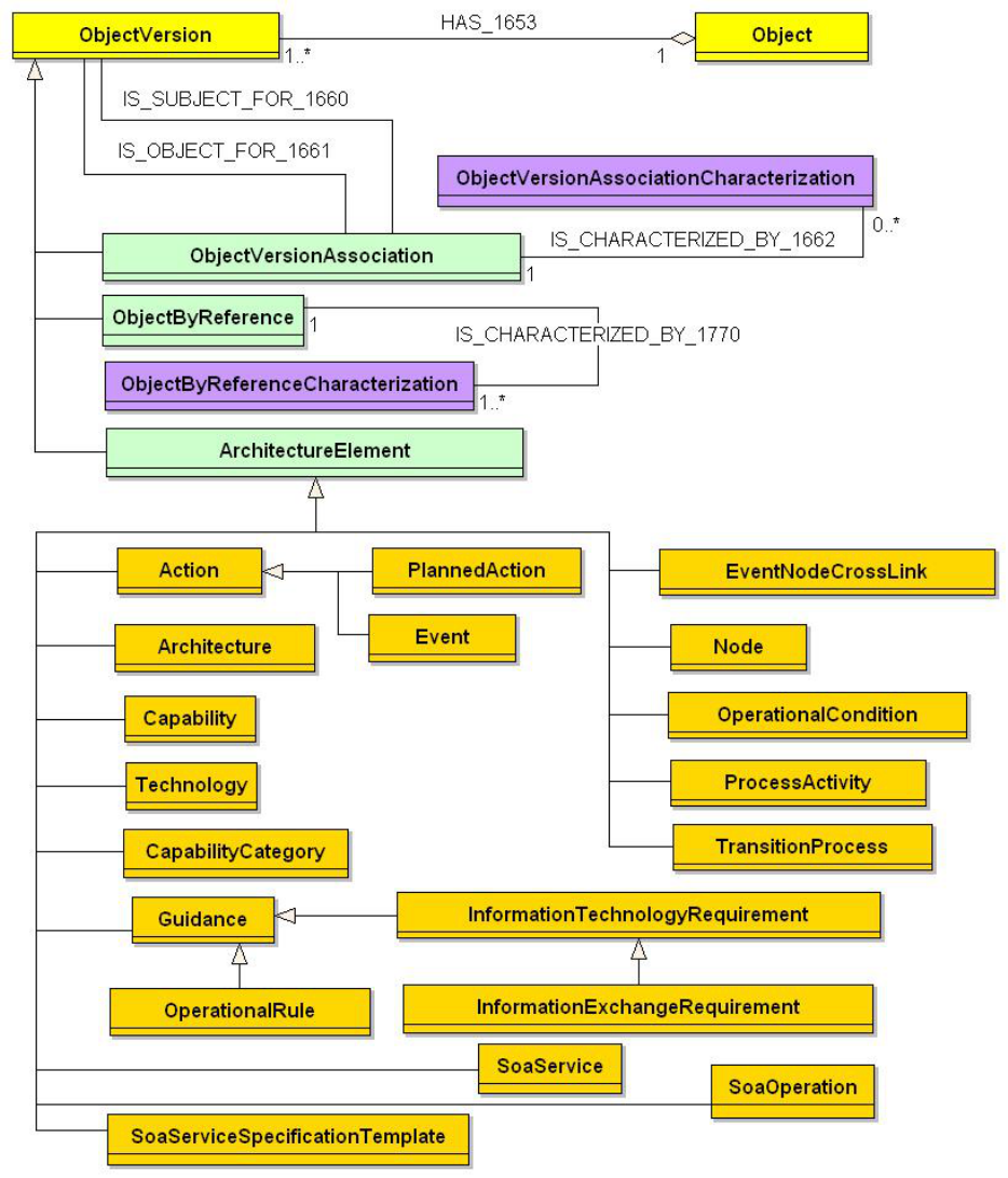
4-53
expressed using CADM v1.5 structures. These and related entities are also shown in Figure
4-18. Capability can be linked to instances of ProcessActivity, and of
InformationTechnologyRequirement to express specific capabilities for threads of IERs and
sequences of operational activities.
Figure 4-18: CADM Diagram for OV-6

4-54
4.6.3 Operational Rules Model (OV-6a)
Product Definition. The OV-6a specifies operational or business rules that are constraints on
an enterprise, a mission, operation, business, or an architecture. While other OV products (e.g.,
OV-1, OV-2, and OV-5) describe the structure of a business—what the business can do—for the
most part, they do not describe what the business must do, or what it cannot do.
At the mission level, OV-6a may consist of doctrine, guidance, rules of engagement, and so
forth. At the operation level, rules may include such things as a military Operational Plan
(OPLAN). At lower levels, OV-6a describes the rules under which the architecture or its nodes
behave under specified conditions. Such rules can be expressed in a textual form, for example,
“If (these conditions) exist, and (this event) occurs, then (perform these actions).”
Product Purpose. At a top level, rules should at least embody the concepts of operations
defined in OV-1, and should provide guidelines for the development and definition of more
detailed rules and behavioral definitions that will occur later in the architecture definition
process.
Product Detailed Description. Rules are statements that define or constrain some aspect of
the mission, or the architecture. It is intended to assert operational structure or to control or
influence the mission thread. As the product name implies, the rules captured in OV-6a are
operational (i.e., mission-oriented), not systems-oriented. These rules can include such guidance
as the conditions under which operational control passes from one entity to another, or the
conditions under which a human role is authorized to proceed with a specific activity.
OV-6a can be associated with the appropriate activities in OV-5. For example, a rule might
prescribe the specific set of inputs required to produce a given output. OV-6a can also be used to
extend the capture of business requirements by constraining the structure and validity of OV-7
elements.
Detailed rules can become quite complex, and the structuring of the rules themselves can
often be challenging. OV-6a extends the representation of business requirements and concept of
operations by capturing, in the form of operational rules expressed in a formal language, both
action assertions and derivations. Examples of formal languages include structured English, LDL
[Naqvi, 1989], and the Object Constraint Language (OCL) [Warmer, 1999]. Action assertions
are constraints on the results that actions produce, such as if-then and integrity constraints.
Derivations are algorithmically derived facts based on other terms, facts, derivations, and/or
action assertions.
Operational rules can be grouped into the following categories:
• Structural Assertions: These rules concern mission or business domain terms
and facts that are usually captured by the entities and relationships of Entity-
Relationship models. They reflect static aspects of business rules that may also
be captured in the OV-7.
− Terms: Entities
− Facts: Association between two or more terms (i.e., relationship)

4-55
• Action Assertions: These rules concern some dynamic aspects of the business
and specify constraints on the results that actions produce. There are three types
of action assertions:
− Condition: This is a guard or if portion of an if-then statement. If
the condition is true, it may signal the need to enforce or test
additional action assertions.
− Integrity Constraint: These must always be true (e.g., a declarative
statement).
− Authorization: This restricts certain actions to certain human roles
or users.
• Derivations: These rules concern algorithms used to compute a derivable fact
from other terms, facts, derivations, or action assertions.
OV-6a can concentrate on the more dynamic Action Assertions and Derivations rules,
because the Structural Assertion rules are usually captured in OV-7. Operational rules are:
• Independent of the modeling paradigm used
• Declarative (non-procedural)
• Atomic (indivisible yet inclusive)
• Expressed in a formal language such as:
− Decision trees and tables
− Structured English
− Mathematical logic
• Distinct, independent constructs
• Mission/business-oriented
Each architecture may select the formal language in which to record its OV-6a. The formal
language selected should be referenced and well documented.
Figure 4-19 illustrates an example Action Assertion that might be part of OV-6a. The
example is given in a form of structured English.
A base fact could be:
“Battle Damage Assessment consists of three activities: Conduct Battle Damage, Conduct
Munitions Effects Assessment, and Recommend Restrike”
Derived facts could be:
“Recommend Restrike activity cannot be completed before a Battle Damage Assessment
Report has been completed.”
“Recommend Restrike activity cannot be completed before a Munitions Effects Assessment
Report has been completed.”
A derivation used to derive this derived fact above would be:
A Restrike Recommendation is based on facts contained in Battle Damage Assessment
Reports, and Munitions Effects Assessment Reports
Figure 4-19: OV-6a – Action Assertion Example
4-56
4.6.4 UML Representation
There is no equivalent diagram in UML. OV-6a is a text-oriented product. It comprises
business rules that apply to operational activities and entities of the Logical Model written in
structured English. OV-6a extends the capture of business requirements and concept of
operations for the use cases and activities of OV-5. If one considers Operational Rules to be
equivalent to complex, nested If-Then-Else and CASE statements, then these statements can be
unambiguously derived from UML statechart diagrams. Guard conditions can be specified for
state transitions. Consequently, OV-6a may be generated via the use of adornments, and the
inclusion of pre- and post-conditions on the use cases of OV-5 (or guard conditions in statechart
diagrams). Operational Rules should trace to the constraint relationships identified in OV-5 and
to the statechart diagrams for the relevant object classes, if they have been defined. There is no
UML diagram to be produced, but the AV-2 will contain these rules and constraints, if they are
incorporated into the model as pre- and post-conditions or other adornments in the UML
diagrams, where applicable.
4.6.5 Net-Centric Guidance for OV-6a
Augmented Product Purpose. In the NCE, the OV-6a is used to capture constraints and
operational policies that affect program-level architectures operating in a net-centric enterprise.
Net-Centric Product Description. The OV-6a traditionally captures business rules and
provides guidelines for the development and definition of more detailed rules and behavioral
definitions that will occur later in the architecture definition process or that provide amplifying
information for those rules and behavioral definitions. Accordingly, in the NCE, the OV-6a
should capture the rules and policies that apply to providing and consuming information (OV-2,
OV-3, OV-5, and/or OV-7) and capabilities in the NCE (including how policies in OV-6a
constrain services and/or service operations in SV-4). Included may be rules and policies for:
• Tagging, posting, and processing information to the NCE (SV-6 and 11)
• Selecting, monitoring, and managing the interactions between consumers and
providers (OV-6b and/or 6c)
• Maintaining any shared infrastructure between providers and consumers (SV-2)
• Ensuring that only authorized consumers have access to the provided
information (OV-3) and capabilities (OV-2, OV-5, and SV-5)
At a highest level, rules should embody the concepts of operations defined in OV-1. In the
NCE, the providers and consumers must communicate and interact with each other as
information is passed and capabilities are used, therefore, additional constraints may apply to the
management of the information and capabilities exchanged between them. Rules may include the
following:
• Requirements and specifications on the acceptable boundaries for reliability,
visibility, accessibility, availability, and performance of information and
capabilities (SV-7)
• Rules for identifying, prioritizing, selecting, enabling, and disabling different
external sources of information and capabilities (OV-2, OV-3, and OV-7 and/or
SV-6 and 11)
4-57
• Rules for identifying, prioritizing, selecting, enabling, and disabling different
external consumers’ information and capabilities (OV-3)
• Guidance for dealing with problems and failures if information and capabilities
cannot be provided or consumed
In the NCE, the infrastructure required for providing and consuming information and
capabilities may be shared between providers and consumers. Rules and policies should be
defined for allocating, provisioning, managing, and maintaining the required infrastructure. The
net-centric OV-6a may facilitate the following efforts:
• Prioritization and allocation of resources and infrastructure
• Coordination of anticipated maintenance, upgrades, evolution paths, and their
implementation schedules (SV-8, TV-2)
It is important to identify information assurance constraints (OV-3, SV-6, TV-1 and 2) and
policies in the NCE in order that information and capabilities are able to be delivered to
authorized users based on access controls, authorization, and authentication.
The OV-6a may capture additional IA rules for programs operating in the NCE.
Authoritative policies that guard or enable access to net-centric services and capabilities may
also be captured in the OV-6a.
4.6.6 CADM Support for OV-6a
Figure 4-20 provides a high-level diagram from the CADM showing key entities that are
used to store architecture data for OV-6a in a CADM-conformant database. Each OV-6a is
represented as an instance of Document with its attribute ArchitectureProductTypeCode = RULE-
MODEL
. This allows the expression of Name, Timeframe, and so on for that architecture product.
The CADM specification for OV-6a also allows the user to describe structural assertions,
action assertions with their respective conditions, as well as the applicable integrity constraints,
authorizations, and derivations via the instantiation of OperationalRule (a subtype of Guidance)
and the use of its attribute LogicalConditionText. Individual rules can be expressed explicitly,
where appropriate, as relationships via the entities ConceptualDataModel, or ActivityModel. Where
the rules pertain to procedural applications of technologies, they can also be stated in formal or
informal terms, as appropriate, as instances of TechnicalGuideline. Where the rules pertain to
needs or demands for the acquisition, storage, manipulation, management, movement, control,
switching, interchange, transmission, or reception of data, they can be expressed via the entity
InformationTechnologyRequirement, and other instances of Guidance. In CADM v1.5, the
attribute TypeCode in OperationalRule can be set to either ACTION-ASSERTION-RULE,
STRUCTURAL-ASSERTION-RULE
, or DATABASE-RULE to refine the semantics of the rules in
question. These rules can be related to each other and to various architecture products through
ObjectVersionAssociation. This enables, for example, the linkage of a specific OV-6a to
instances of OperationalRole.

4-58
Figure 4-20: CADM Diagram for OV-6a

4-59
4.6.6.1 OV6a – Data Element Definitions
AV-2 should capture information about the rules specified in OV-6a. For example, the
dictionary should have information on the type of rule (i.e., Structural Assertion, Action
Assertion, or Derivation), the text for the rule, and the relationship between the rules and other
architecture product data elements, such as activities from OV-5 or entities from OV-7. Table
4-6 describes the architecture data elements for OV-6a.
OV-6a Information Space
Action
†
Architecture
†
Document
†
Guidance
†
InformationAsset
†
InformationExchangeRequirement
†
InformationTechnologyRequirement
†
OperationalRole
†
ProcessActivity
†
SoaOperation
†
SoaService
†
SoaServiceSpecificationTemplate
†
ConceptualDataModel
DataAttribute
DataEntity
Event
OperationalRule
TechnicalGuideline
†)
The descriptions of these elements have been provided in the preceding sections
Table 4-6: Data Element Definitions for OV-6a
Data Elements Attributes Definition
ConceptualDataModel
creatorIdentifierText The text that identifies the agent responsible for creating a
specific ConceptualDataModel.
Development
MethodologyName
The name of the procedure used to develop a
ConceptualDataModel.
developmentStatus
IdentifierText
The text that identifies the state of development of a
ConceptualDataModel.
developmentToolName The name of the mechanism used to develop a
ConceptualDataModel.
notationStyleName The name of the memorandum manner used in a
ConceptualDataModel.
purposeText The text of the intention of a ConceptualDataModel.
refinementLevelCode The code that represents the level of refinement of a
ConceptualDataModel.
revisionEffective
CalendarDate
The effective date of an amendment to a
ConceptualDataModel.
scopeText The text of the boundaries of a ConceptualDataModel.
statusEffectiveCalendar
Date
The effective date of the state of a ConceptualDataModel.
tenseCode The code that represents the time distinction of a
ConceptualDataModel.
tenseEffectiveCalendar
Date
The effective date of the time distinction of a
ConceptualDataModel.
DataAttribute
characteristicName The name of a property of a DataAttribute.
referenceSource
IdentifierText
The text that identifies the basis for creation of a
DataAttribute.
revisionCalendarDate The amendment date of a DataAttribute.
statusCategoryCode The code that represents the classification of a
DataAttribute.

4-60
Data Elements Attributes Definition
timelinessCode The code that represents the frequency update of a
DataAttribute.
validationProcedureText The text that describes the verification methodology of a
DataAttribute.
xmlLongTagName The name of the marker defined for use in xml associated
with a specific DataAttribute.
xmlShortTagName The shortened form of the name of the marker defined for
use in xml associated with a specific DataAttribute.
DataEntity
dependencyCode The code that represents whether a specific DataEntity
depends on any other DataEntity for its primary key.
revisionCalendarDate The amendment date of a DataEntity.
scopeText The text of the extent of a DataEntity.
statusCategoryCode The code that represents a classification of a DataEntity.
xmlLongTagName The name of the marker defined for use in xml associated
with a specific DataEntity.
xmlRecordDelimiter
LongTagName
The name of the marker defined for use in xml to identify the
beginning and end of a record associated with a specific
DataEntity.
xmlRecordDelimiter
ShortTagName
The name in abbreviated form of the marker defined for use
in xml to identify the beginning and end of a record
associated with a specific DataEntity.
xmlShortTagName The shortened form of the name of the marker defined for
use in xml associated with a specific DataEntity.
Event
beginCalendarDateTime The calendar date-time on which an Event starts.
endCalendarDateTime The calendar date-time on which an Event concludes.
observationTypeCode The code that represents the kind of observation associated
with a specific Event.
typeCode The code that represents a kind of Event.
categoryCode The code that represents a class of Event.
OperationalRule
databaseCategoryCode The code that represents a class of data-cascading
requirement for a specific OperationalRule.
categoryCode The code that represents a class of OperationalRule.
formalLanguageName The name of the semantics use to express a specific
OperationalRule.
formalLanguageSource
Name
The name of the authoritative specification for the semantics
used in a specific OperationalRule.
logicalConditionText The text that defines a clause upon which the truth of an
OperationalRule depends.
TechnicalGuideline
categoryCode The code that represents a class of TechnicalGuideline.
Relationships
Parent Verb Phrase Child
Action
may produce
Event
ConceptualDataModel
cites
DiscoveryMetadata
DataAttribute
is related to
DataAttribute
DataAttribute
is included in
DataEntity
DataEntity
is described by
DataAttribute
DataEntity
is used in the design of
DataAttribute

4-61
Relationships
Parent Verb Phrase Child
DataEntity
is related to
DataEntity
Event
is related to
Event
Event
is cited in
Document
Event
may be the trigger for
InformationExchangeRequirement
OperationalRule
limits
Action
SoaService
has
SoaOperation
(All previous relationships for the listed entities that comprise the information space of OV-6a should be considered
part of the specification for this product, as well as those for the entities modeled via ObjectByReference and
ObjectVersionAssociation. For the latter, see Volume III.)
4.6.7 Operational State Transition Description (OV-6b)
Product Definition. The OV-6b is a graphical method of describing how an operational node
or activity responds to various events by changing its state. The diagram represents the sets of
events to which the architecture will respond (by taking an action to move to a new state) as a
function of its current state. Each transition specifies an event and an action.
Product Purpose. The explicit sequencing of activities in response to external and internal
events is not fully expressed in OV-5. An OV-6b can be used to describe the explicit sequencing
of the operational activities. Alternatively, OV-6b can be used to reflect the explicit sequencing
of actions internal to a single operational activity or the sequencing of operational activities with
respect to a specific operational node.
Product Detailed Description. OV-6b is based on the statechart diagram. A state machine is
defined as “a specification that describes all possible behaviors of some dynamic model element.
Behavior is modeled as a traversal of a graph of state nodes interconnected by one or more
joined transition arcs that are triggered by the dispatching of a series of event instances. During
this traversal, the state machine executes a series of actions associated with various elements of
the state machine.” [OMG, 2003]
The product relates states, events, and actions. A state and its associated action(s) specify the
response of an operational activity to events. When an event occurs, the next state may vary
depending on the current state (and its associated action), the event, and the rule set or guard
conditions. A change of state is called a transition. Each transition specifies the response based
on a specific event and the current state. Actions may be associated with a given state or with the
transition between states.
Statechart diagrams can be unambiguously converted to structured textual rules that specify
timing aspects of operational events and the responses to these events, with no loss of meaning.
However, the graphical form of the state diagrams can often allow quick analysis of the
completeness of the rule set, and the detection of dead ends or missing conditions. These errors,
if not detected early during the operational analysis phase, can often lead to serious behavioral
errors in fielded systems or to expensive correction efforts.
Figure 4-21 provides a template for a simple OV-6b. The black dot and incoming arrow
point to initial states (usually one per diagram), while terminal states are identified by an
outgoing arrow pointing to a black dot with a circle around it. States are indicated by rounded
corner box icons and labeled by name or number and, optionally, any actions associated with that
state. Transitions between states are indicated by one-way arrows labeled with an event/action

4-62
notation that indicates an event-action pair, and which semantically translates to: when an event
occurs, the corresponding action is executed. This notation identifies the event that causes the
transition and the ensuing action (if any) associated with the transition.
State 2State 1
Event / Guard Condition / Action
State 2State 1
Event / Guard Condition / Action
State 2State 1
Event / Guard Condition / Action
Figure 4-21: OV-6b – High-Level Template
Another dynamic behavior modeling technique is Colored PetriNet (CPN) [Kristensen,
1998]. A CPN can be used as an executable operational architectural model or a business
workflow model. CPN executable models provide a description of the activity event sequencing
(concurrent or consecutive) and can be used to dynamically simulate an OV-5. With a CPN
simulation engine or a discrete event workflow simulation engine, parallel event processing and
decision support can be achieved.
The most important reason for using both modeling and simulation tools is to show complex,
dynamic organizational interactions that cannot be identified or properly understood using static
models. Simulation provides insight into how processes in an enterprise add to the overall cost of
a mission thread or scenario and can make it possible to animate, analyze, and validate these
complex relationships. This information can then be used to create new alternatives or it can be
used to compare multiple alternatives until an optimal solution is found. Most importantly,
simulation takes information that traditionally was collected in static reports, and makes this
information dynamic.
Dynamic analysis is able to assess time-dependent process behavior and shared time-
dependent resources, discover ways to efficiently allocate human and system resources to
perform those processes, check overall performance, identify bottlenecks and human resource
overloads caused by insufficient resources or faulty information flows, and discover and
eliminate duplication of effort. Measures of Effectiveness (MOE) relative to mission objectives
being evaluated and Measures of Operational Outcomes (MOO) relative to how operational
requirements contribute to end results can be determined.
In addition to examining behavior over time, one can also assess an overall dynamic mission
cost over time in terms of human and system/network resource dollar costs and their processes
dollar costs. Analysis of dollar costs in executable architectures is a first step in an architecture-
based investment strategy, where we eventually need to align architectures to funding decisions
to ensure that investment decisions are directly linked to mission objectives and their outcomes.
Figure 4-22 illustrates the anatomy of one such dynamic model.

4-63
Organization Chart
Organization Chart
Resources
Resources
Info
Info
Containers
Containers
Activities
Activities
Information
Information
Applications,
Applications,
Databases,
Databases,
Servers,
Servers,
Networks
Networks
Process Model
Process Model
Job Titles
Job Titles
Business Entities
Business Entities
Human Roles, Jobs:
Human Roles, Jobs:
-
-
Wing Cdr, S3, XO,
Wing Cdr, S3, XO,
VP, clerk
VP, clerk
Organizational Structure
Organizational Structure
-
-
BN, Wing, Fleet,
BN, Wing, Fleet,
Finance Dept
Finance Dept
Systems, W/S,
Systems, W/S,
Satellites,
Satellites,
Equipment,
Equipment,
Techniques, Tools,
Techniques, Tools,
ATM, Networks
ATM, Networks
Inputs/Outputs
Inputs/Outputs
Triggers
Triggers
Inputs/Outputs
Inputs/Outputs
Call for Fire, Produce ATO
Call for Fire, Produce ATO
Conduct Mission Planning,
Conduct Mission Planning,
Process Loan Application
Process Loan Application
Actual Organization Unit -
1-8 Armor BN, Widget Fin Dept
Organization Chart
Organization Chart
Resources
Resources
Info
Info
Containers
Containers
Activities
Activities
Information
Information
Applications,
Applications,
Databases,
Databases,
Servers,
Servers,
Networks
Networks
Process Model
Process Model
Job Titles
Job Titles
Business Entities
Business Entities
Human Roles, Jobs:
Human Roles, Jobs:
-
-
Wing Cdr, S3, XO,
Wing Cdr, S3, XO,
VP, clerk
VP, clerk
Organizational Structure
Organizational Structure
-
-
BN, Wing, Fleet,
BN, Wing, Fleet,
Finance Dept
Finance Dept
Systems, W/S,
Systems, W/S,
Satellites,
Satellites,
Equipment,
Equipment,
Techniques, Tools,
Techniques, Tools,
ATM, Networks
ATM, Networks
Inputs/Outputs
Inputs/Outputs
Triggers
Triggers
Inputs/Outputs
Inputs/Outputs
Call for Fire, Produce ATO
Call for Fire, Produce ATO
Conduct Mission Planning,
Conduct Mission Planning,
Process Loan Application
Process Loan Application
Actual Organization Unit -
1-8 Armor BN, Widget Fin Dept
Figure 4-22: Anatomy of an Executable Operational Architecture
State transitions in executable operational architectural models provide for descriptions of
conditions that control the behavior of process events in responding to inputs and in producing
outputs. A state specifies the response of a process to events. The response may vary depending
on the current state and the rule set or conditions. Distribution settings determine process time
executions. Examples of distribution strategies include: constant values, event list, constant
interval spacing, normal distribution, exponential distribution, and so forth. Priority determines
the processing strategy if two inputs reach a process at the same time. Higher priority inputs are
usually processed before lower priority inputs.
Processes receiving multiple inputs need to define how to respond. Examples of responses
include: process each input in the order of arrival independent of each other, process only when
all inputs are available, or process as soon as any input is detected. Processes producing multiple
outputs can include probabilities (totaling 100 percent), under which each output would be
produced.
Histograms are examples of generated timing descriptions. They are graphic representations
of processes, human and system resources, and their used capacity over time during a simulation
run. These histograms are used to perform dynamic impact analysis of the behavior of the
executable architecture. Figure 4-23 is an example showing the results of a simulation run of
human resource capacity.

4-64
Figure 4-23: Sample Histograms Showing Results of a Simulation Run
4.6.8 UML Representation
OV-6b may be produced in UML using statechart diagrams that contain simple states and
composite states. They also contain transitions, which are described in terms of triggers or events
(generated as a result of an action) and guard conditions associated with the events, and an action
or sequence of actions that are executed as a result of the event taking place. Statechart diagrams
specify the reaction of an object to stimuli as a function of its internal state. Guard conditions of
a statechart diagram map to the pre-conditions of an OV-5 use case. Activities in an activity
diagram (OV-5) should correlate to states of the relevant object classes (operational nodes) and
match to the statechart diagram states for the same object classes, where a state is defined in
UML 1.4 as “A condition or situation during the life of an object during which it satisfies some
condition, performs some activity, or waits for some event.” Transitions on the activity diagrams
should correlate to the transitions on the state diagrams. In essence, an activity diagram for
multiple operational nodes (or objects using swimlanes) should be mappable to a set of statechart
diagrams for those operational nodes, and to a set of sequence diagrams (where each sequence
diagram correlates to a specific use case scenario). Events or triggers associated with the
transitions on the state diagrams correlate to the triggering events documented in OV-3 and are
the same events shown on the sequence diagrams of OV-6c.
4.6.9 Net-Centric Guidance for OV-6b
Augmented Product Purpose. In a net-centric architecture, the OV-6b is used to describe
the set of state transitions for providers and consumers in the NCE in response to the posting of
information to the NCE or retrieving of information from the NCE.
Product Detailed Description. The traditional OV-6b relates states, events, and actions
associated to transitions between states. Accordingly, in the NCE, the OV-6b should capture
states, events, and actions of providers and consumers accessing information and capabilities
from the NCE. To further enable multiple uses of data and information in the NCE beyond their
original predefined use, data asset providers should post before processing.
30
The net-centric
OV-6b identifies when information assets are in an initially useful state, and where information
assets are made available and posted to the NCE, except when limited by policy, regulation, or
security. The time and process implications of post before processing are reflected as operational
changes to the business and mission processes in the OV-6 architecture products.
30
DoD Net-Centric Data Strategy, May 9, 2003
4-65
4.6.10 CADM Support for OV-6b
Figure 4-24 provides a high-level diagram from the CADM showing key entities that are
used to store architecture data for OV-6b in a CADM-conformant database. Each OV-6b is
represented as an instance of Document, with its attribute ArchitectureProductTypeCode = STATE-
TRANSITION-DESCRIPTION
. This permits recording the Name, Timeframe, and so forth for this
DoDAF product.
The CADM specification for OV-6b also allows the user to describe all the relevant
components of a state transition diagram by the proper instantiation of ProcessEvent,
TransitionProcess, and ProcessStateVertex. Additional characterization is supported through the
use of ObjectByReference (see Volume III for details).
In addition to the entities mentioned above, the CADM v1.5 structures, ProcessActivity,
Action, and Event, can be employed to capture the information content of an OV-6b. In this
manner, it is possible to relate TransitionProcess to Action as well as types of events called out in
UML:
SIGNAL-EVENT, CALL-EVENT, TIME-EVENT, and CHANGE-EVENT. In CADM, it is also
possible to link an OV-6b to a specific System (including a specific component), a SoftwareItem,
or to a Task.

4-66
Figure 4-24: CADM Diagram for OV-6b

4-67
4.6.10.1 OV-6b – Data Element Definitions
OV-6b describes the detailed time sequencing of activities or work flow in the business
process, depicting how the current state of a process or activity changes in response to external
and internal events. Table 4-7 describes the architecture data elements for OV-6b.
OV-6b Information Space
Action
†
Architecture
†
Document
†
Event
†
Guidance
†
InformationElement
†
OperationalRule
†
ProcessActivity
†
System
†
OperationalCondition
PlannedAction
ProcessEvent
ProcessStateVertex
TransitionProcess
†)
The descriptions of these elements have been provided in the preceding sections
Table 4-7: Data Element Definitions for OV-6b
Data Elements Attributes Definition
OperationalCondition
formalSpecificationText The text that summarizes a specific OperationalCondition.
hierarchyName The name that designates the relationship of a specific
OperationalCondition to other OperationalCondition.
valueText The text that describes the quantity associated with a specific
OperationalCondition.
PlannedAction
categoryCode The code that represents a class of PlannedAction.
plannedEndCalendar
Datetime
The calendar date and time of the expected conclusion of a
PlannedAction.
plannedStartCalendar
Datetime
The calendar date and time of the expected beginning of a
PlannedAction.
purposeDescriptionText The text that summarizes the objective of a specific
PlannedAction.
ProcessEvent
booleanExpressionText The text that represents the logical statement whose truth
indicates when a ProcessEvent occurs.
categoryCode The code that represents a class of ProcessEvent.
elapsed-timeQuantity The elapsed-time quantity that represents a time deadline for
a ProcessEvent.
operationDescription
Text
The text that characterizes the operation whose invocation is
requested in a specific ProcessEvent.
ProcessStateVertex
categoryCode The code that represents a class of ProcessStateVertex.
concurrencyCode The code that represents the specification of decomposition
semantics for a specific ProcessState.
subcategoryCode The code that represents a detailed class of
ProcessStateVertex.
TransitionProcess
labelName The name that represents a specific TransitionProcess in a
diagram.

4-68
Relationships
Parent Verb Phrase Child
Event
may be a
ProcessEvent
InformationElement
is the subject of
TransitionProcess
OperationalCondition
is related to
OperationalCondition
OperationalCondition
may be a guard for
OperationalRule
OperationalRule
is guard condition for
TransitionProcess
ProcessEvent
triggers
TransitionProcess
ProcessStateVertex
is source for
TransitionProcess
ProcessStateVertex
is target for
TransitionProcess
(All previous relationships for the listed entities that comprise the information space of OV-6b should be considered
part of the specification for this product, as well as those for the entities modeled via ObjectByReference and
ObjectVersionAssociation. For the latter, see Volume III.)
4.6.11 Operational Event-Trace Description (OV-6c)
Product Definition. The OV-6c provides a time-ordered examination of the information
exchanges between participating operational nodes as a result of a particular scenario. Each
event-trace diagram should have an accompanying description that defines the particular
scenario or situation.
Product Purpose. OV-6c is valuable for moving to the next level of detail from the initial
operational concepts. The product helps define node interactions and operational threads. The
OV-6c can also help ensure that each participating operational node has the necessary
information it needs at the right time in order to perform its assigned operational activity.
Product Detailed Description. OV-6c allows the tracing of actions in a scenario or critical
sequence of events. OV-6c can be used by itself or in conjunction with OV-6b to describe the
dynamic behavior of business processes or a mission/operational thread. An operational thread is
defined as a set of operational activities, with sequence and timing attributes of the activities, and
includes the information needed to accomplish the activities. A particular operational thread may
be used to depict a capability. In this manner, a capability is defined in terms of the attributes
required to accomplish a given mission objective by modeling the set of activities and their
attributes. The sequence of activities forms the basis for defining and understanding the many
factors that impact the capability.
Integrated architectures with DOTMLPF information provide a structured and organized
approach for defining capabilities and understanding the underlying requirements for achieving
those capabilities. By describing the sequence and timing of activities, tying them to the
operational nodes (representing organizations or human roles), relating them to their supporting
systems or system functions, and specifying the actions, events, and related guard conditions or
business rules that constrain those activities, the full spectrum of DOTMLPF is modeled and
related, so that analyses and decisions can be supported. Below is a detailed description of how
DOTMLPF is tightly woven into this and related products.
• Doctrine is represented as guard conditions, which are associated with events,
which, in turn, map to controls in OV-5.
• Organization is represented via the lifelines or swimlanes, which map to
operational nodes of OV-2, which, in turn, map to organizations, organization
types, or human roles of OV-4, and mechanisms in OV-5.
4-69
• Training is represented via the lifeline or swimlane, since the operational node
(shown on the diagram as a lifeline or swimlane) may represent a human role,
which, in turn, embodies a certain skill set or knowledge domain required to
perform the actions (which are, in turn, related to operational activities of
OV-5).
• Materiel is tied to the elements in OV-6c, because this product is tightly coupled
with OV-5, where mechanisms may be used to represent systems that support
operational activities. Materiel is tied to the elements in OV-6c, because this
product is tightly coupled with OV-3, where the information exchanges are tied
to operational activities. Further materiel detail may be related to the activities
via SV-5, by relating those activities to the system functions that are executed
by systems that automate them (wholly or partially). Each operational thread or
scenario (represented by an OV-6c) is associated with a certain capability, since
a capability is defined in terms of the activities and their attributes depicted in
OV-6c. Consequently, an SV-5 may also be used to relate a capability to the
systems that support it, by labeling a set of activities with their associated
capability (defined in OV-6c), and by labeling the system functions with the
systems that execute them (defined in SV-1, SV-2, and SV-4).
• Leadership may be represented either directly via the lifeline or swimlane or
indirectly through the relationships of an operational node (shown as a lifeline
or swimlane on the diagram) in OV-2 to organizations, organization types, or
leadership human roles in OV-4.
• Personnel may be represented directly via the lifeline or swimlane, or indirectly
through the relationships of an operational node (shown as a lifeline or
swimlane on the diagram) in OV-2 to organizations, organization types, or
human roles in OV-4.
• Facility is tied to the elements in OV-6c, because the lifeline or swimlane
representing an operational node is directly tied to the systems node (facilities)
that house the systems, which may be shown as mechanisms that support
operational activities.
The Framework does not endorse a specific event-trace modeling methodology. Two such
types of models include UML sequence diagrams [OMG, 2003] and IDEF3 [IDEF3, 1995]. The
OV-6c product may be developed using any modeling notation that supports the layout of timing
and sequence of activities along with the information exchanges that occur between operational
nodes for a given scenario. Different scenarios should be depicted by separate diagrams. Figure
4-25 provides a template for an OV-6c using a UML diagram. The items across the top of the
diagram are operational nodes, usually organizations, organizations types, or human roles, which
take action based on certain types of events. Each operational node has a lifeline associated with
it that runs vertically. Specific points in time can be labeled on the lifelines, running down the
left-hand side of the diagram. One-way arrows between the node lifelines represent events, and
the points at which they intersect the lifelines represent the times at which the nodes become
aware of the events. Events represent information passed from one lifeline to another and actions
associated with the event. Labels indicating timing constraints or providing descriptions can be
shown in the margin or near the event arrow that they label. The direction of the events
represents the flow of control from one node to another.

4-70
MESSAGES/TIME
Operational Nodes
OP NODE 1
OP NODE 2
OP NODE 3
Event 1
time 1
time 2
time 3
time 3'
{formula relating
time 3 to time 3'}
time n
{formula relating
time 1 to time 2}
Event 2
Event 3
Event 5
Event 4
Event 6
Event 7
Event 8
MESSAGES/TIME
Operational Nodes
OP NODE 1
OP NODE 2
OP NODE 3
Event 1
time 1
time 2
time 3
time 3'
{formula relating
time 3 to time 3'}
time n
{formula relating
time 1 to time 2}
Event 2
Event 3
Event 5
Event 4
Event 6
Event 7
Event 8
Figure 4-25: OV-6c – UML-type Template
Figure 4-26 shows an example of an OV-6c using IDEF3 notation. Boxes convey a Unit of
Behavior (UOB), which is a step in the process and ties to an Operational Activity in OV-5 via
an IDEF0 Reference Property. A swimlane represents a horizontal or vertical division of the
diagram for showing what operational nodes perform what processes UOBs, and links show
control flow between UOBs (not information flow). IDEF3 link types include temporal
(sequence, precedence) and logical (guard conditions or business rules).

4-71
Customer
Customer Care
Accounts
Release Room
Go-to/
A4142.1.7
Inform Client
Payment Invalid
A4142.1.6
Send Confirmation
to Client
A2132.1.5
Reserve Room
A3112.1.4
Check Payment
Details
A3112.1.3
Take Payment
Details
A1142.1.2
Check
Reservation Details
2.1.1
Customer
Confirms
Reservation
X
X
Precedence link
indicates
order between
UOBs
Operational
Node or
Swimlane
Junction, shows
decision
logic (alternate
paths)
OV-5
Activity
Reference
Number
Annotation
UOB
Customer
Customer Care
Accounts
Release Room
Go-to/
A4142.1.7
Inform Client
Payment Invalid
A4142.1.6
Send Confirmation
to Client
A2132.1.5
Reserve Room
A3112.1.4
Check Payment
Details
A3112.1.3
Take Payment
Details
A1142.1.2
Check
Reservation Details
2.1.1
Customer
Confirms
Reservation
X
X
Precedence link
indicates
order between
UOBs
Operational
Node or
Swimlane
Junction, shows
decision
logic (alternate
paths)
OV-5
Activity
Reference
Number
Annotation
UOB
Figure 4-26: OV-6c – IDEF3 Example
4.6.12 UML Representation
Using the UML, the activity diagram best captures OV-6c information (Figure 4-27). Many
DoDAF architects may believe that the sequence diagram best captures OV-6c; however, as
discussed in the UML Representation OV-5 section, UML use cases are “instantiateable.”
Because they instantiate, a use case can render many possible sequences of events.
Establishes the
Establishes the
condition (instance)
condition (instance)
of the use case for
of the use case for
the purpose of the
the purpose of the
Operational Event
Operational Event
-
-
Trace Description
Trace Description
Use Case 1
<<use case>>
Use Case 2
<<use case>>
Use Case 3
<<use case>>
[ guard condition ]
[ guard condition ]
Figure 4-27: UML Representation of an Operational Event-Trace (OV-6c)

4-72
For example (see Figure 4-16, UML Example OV-5), if the guard condition were “message
distribution required,” then the sequence Present Alerts and Notifications executes after
Determine Mission Processing Needs is complete. Therefore, the use case would instantiate to
include the sequence for both Determine Mission Processing Updates and Present Alerts and
Notifications. Otherwise, the use case would instantiate to include Determine Mission Processing
Needs sequence only. Although the architect could create a sequence diagram for OV-6c, for
complex architectures, they would quickly become a maintenance problem as the use cases
mature over time. For example, if the architect decides to modify the sequence diagram of the
use case, the sequence diagram of the OV-6c would require modification as well and there might
be more than one OV-6c. Using this approach, the architect modifies the sequence diagrams of
the use case and the OV-6c is still intact unless a guard condition of the use case changes that,
then affects the related OV-6c depiction. This approach is object-oriented in that it takes
advantage of the multiple abstraction mechanisms the UML offers. Using the activity view of the
OV-6c, it is possible in some tools to automatically generate a complete sequence diagram
depicting a more traditional OV-6c. This approach is acceptable, because the architect does not
need to manually resolve changes.
4.6.13 Net-Centric Guidance for OV-6c
Augmented Product Purpose. In the NCE, the OV-6c ensures that the information and
capabilities required by operational nodes, specifically with the operational role of Service
Functionality Provider and Service Consumer, are available in a time ordered sequence to
perform NCO. The Unanticipated User must be accounted for, but cannot be time-phased.
Product Detailed Description. The OV-6c traditionally describes operational activities,
along with sequence, timing attributes, and information needed to accomplish them.
Accordingly, the net-centric OV-6c is used to capture the time ordered sequencing of
information and capabilities exchanged between operational nodes with operational roles of
Service Functionality Provider, Service Consumer, and Unanticipated User that appear in the
net-centric OV-5. These exchanges are the inputs and outputs of activities performed in the NCE,
and the sequencing highlights when and how often information and data are posted to the NCE
or retrieved from external sources.
In the NCE, the OV-6c may depict the following:
• Exchanges between the Service Functionality Providers and Service
Consumers, the Service Consumers and external Service Functionality
Providers, and between the Service Functionality Providers and Unanticipated
Users
• Sequences that describe the timeline for the availability of information for any
of its refinement states (raw, pre-processed, fused, etc.)
• Handling, methodologies, and the Enterprise Information Environment (EIE)
infrastructure components that support the operational concepts of post before
processing
31
31
DoD Net-Centric Data Strategy, May 9, 2003
4-73
• Illustration of one-to-many, many-to-one, and many-to-many exchanges
between Service Functionality Providers and Service Consumers found in the
net-centric OV-3.
The net-centric OV-6c describes the business and mission processes that need to be executed
to achieve NCO. The ability to discover, access, and understand information and capabilities
from the NCE, where and when they are needed, is supported by the OV-6c and can be
decomposed to the level of specificity required for the subject architecture.
4.6.14 CADM Support for OV-6c
Figure 4-28 provides a high-level diagram from the CADM v1.5 showing key entities
that are used to store architecture data for OV-6c in a CADM-conformant database. Each OV-6c
is represented as an instance of Document with its attribute ArchitectureProductTypeCode =
EVENT-TRACE-DESCRIPTION. This permits recording the Name, Timeframe, and so forth for this
DoDAF product.

4-74
Figure 4-28: CADM Diagram for OV-6c

4-75
In CADM v1.5, it is possible to state (relative) timelines (or lifelines) for instances of Node.
Each such Node can be explicitly associated with a MissionArea, Organization, OrganizationType,
ProcessActivity
32
, System, and Task. One can also relate two Node instances differing with regard
to their timelines. The definition of such relations can be treated as independent architectural
statements and reused from one scenario to another. For these temporal relations, one can specify
their start at explicit or implicit (computed) absolute or relative times. Relative times can be
specified in terms of the start or end of another temporal relation (using a method analogous to
one defined for temporally related Action instances). A specific OV-6c can be associated to an
OperationalScenario. As noted in the general description of OV-6 products (above), CADM v1.5
supports the linkage of OV-6c to capabilities.
4.6.14.1 OV-6c – Data Element Definitions
OV-6c Information Space
Action
†
Architecture
†
Document
†
Event
†
Guidance
†
InformationExchangeRequirement
†
InformationTechnologyRequirement
†
MissionArea
†
Node
OperationalRole
†
Organization
†
OrganizationType
†
ProcessActivity
†
ProcessEvent
†
SoaOperation
†
SoaService
†
SoaServiceSpecificationTemplate
†
System
†
Task
†
†)
The descriptions of these elements have been provided in the preceding sections
32
In CADM v1.5 the linkage between Node and ProcessActivity is used in the OV-6c to represent the lifeline associated with one or more
operational activities. When ProcessActivity is specialized as a system function this same entity is used in SV-10c to represent the lifeline
associated with one or more system functions.
4-76
4.7 LOGICAL DATA MODEL (OV-7)
4.7.1 OV-7 – Product Description
Product Definition. The OV-7 describes the structure of an architecture domain’s system
data types and the structural business process rules (defined in the architecture’s OV) that govern
the system data. It provides a definition of architecture domain data types, their attributes or
characteristics, and their interrelationships.
Product Purpose. OV-7, including the domain’s system data types or entity definitions, is a
key element in supporting interoperability between architectures, since these definitions may be
used by other organizations to determine system data compatibility. Often, different
organizations may use the same entity name to mean very different kinds of system data with
different internal structure. This situation will pose significant interoperability risks, as the
system data models may appear to be compatible, each having a Target Track data entity but
having different and incompatible interpretations of what Target Track means.
An OV-7 may be necessary for interoperability when shared system data syntax and
semantics form the basis for greater degrees of information systems interoperability, or when a
shared database is the basis for integration and interoperability among business processes and, at
a lower level, among systems.
Product Detailed Description. OV-7 defines the architecture domain’s system data types (or
entities) and the relationships among the system data types. For example, if the domain is missile
defense, some possible system data types may be trajectory and target with a relationship that
associates a target with a certain trajectory. On the other hand, architecture data types for the
DoDAF (i.e., DoDAF-defined architecture data elements, AV-2 data types, and CADM entities)
are things like an operational node or operational activity. OV-7 defines each kind of system
data type associated with the architecture domain, mission, or business as its own entity, with its
associated attributes and relationships. These entity definitions correlate to OV-3 information
elements and OV-5 inputs, outputs, and controls.
Although they are both called data models, OV-7 should not be confused with the CADM.
OV-7 is an architecture product and describes information about a specific architecture domain.
The CADM is not an architecture product. The CADM is a database design for a repository of
DoDAF products and architecture data. CADM-based repositories can store architecture
products, including Logical Data Models, from any DoDAF-based architecture project. Thus, the
CADM addresses a structure for storing architecture data (e.g., instances of operational nodes
and operational activities), while a Logical Data Model for missile defense, for example, might
define architecture domain entities and relationships such as missile tracks and points of impact.
The purpose of a given architecture helps to determine the level of detail needed in this
product. A formal data model (e.g., the Integrated Definition for Data Modeling [IDEF1X])
[FIPS 184, 1993] that is detailed down to the level of architecture domain system data, their
attributes, and their relationships is required for some purposes, such as when validation of
completeness and consistency is required for shared data resources. However, for other purposes,
a higher-level conceptual data model of the domain of interest will suffice, such as a subject area
model or an entity-relation model without attributes. The term logical data model is used here in
this context, regardless of the level of detail the model exhibits.

4-77
The architecture data elements for OV-7 include descriptions of entity, attribute, and
relationship types. Attributes can be associated with entities and with relationships, depending on
the purposes of the architecture.
Figure 4-29 provides a template for OV-7 (with attributes). The format is intentionally
generic to avoid implying a specific methodology.
Entity
Name
Relationship
Attributes
• .....
• .....
• .....
• .....
• .....
• .....
Relationship
Name
Figure 4-29: OV-7 – Template
4.7.2 UML Representation
OV-7 may be modeled in UML using a class diagram. See Figure 4-30. Class diagrams offer
all the UML elements needed to produce entity-relationship diagrams. Class diagrams consist of
classes, interfaces, collaborations, dependency, generalization, association, and realization
relationships. The attributes of these classes can be expanded to include associations and
cardinality [Booch, 1999]. Classes that appear in an OV-7 class diagram correlate to OV-3
information elements and OV-5 inputs, outputs, and controls. The OV-7 class diagram is a
separate diagram from the class diagrams that may be developed for other products (e.g., OV-4).

4-78
Figure 4-30: UML Class Diagram for OV-7 – Template
4.7.3 Net-Centric Guidance for OV-7
Augmented Product Purpose. In the NCE, the OV-7 describes the structure of data types
(information elements) for information being made available or being consumed by the OV-5
activities and provides the organization and composition of metadata that can be used to
characterize the information exchanged in the NCE.
Net-Centric Product Description. The OV-7 traditionally defines the architecture domain’s
system data types (or entities) and the relationships among the system data types. The net-centric
OV-7 provides the same, but with an emphasis on two concerns: 1) describing data types for
information being exchanged between nodes, and 2) using standards or commonly understood
COI guidance for domain vocabularies, taxonomies, and upper-level ontologies. net-centricity
relies on the use of commonly understood vocabularies and meanings to facilitate better
information sharing in the NCE. A net-centric OV-7 supports data understandability in the NCE
by defining the data and its relationships agreed to by a collaborative COI. These agreements
may be documented in more detail in the SV-11 as a specific information agreement or schema
for use in the NCE.
In the NCE, information and capabilities (provided as services) should be tagged so that they
are easily discoverable in the NCE. Accordingly, a specific use of the OV-7 product to support
net-centricity may be the documentation of the organization and composition of metadata
structures for discovery. This may include the descriptive information and capabilities being
offered as specified by DoD Discovery Metadata Specification (DDMS)
33
and any COI
extensions specific to the architecture, or the required and optional metadata that supports the
33
"Department of Defense Discovery Metadata Specification", Version 1.3. 29 July 2005

4-79
description of services (i.e., the SST) with which the architecture complies with. The OV-7
metadata may be used to provide the structural constraints for XML data structures described in
Data Catalogs (local or enterprise). As information and capability assets are tagged and provided
in appropriate repositories (DoD Metadata Registry, data catalogs, or service registries), Service
Consumers and Unanticipated Users can more easily search for and discover these assets to
execute their missions more effectively and efficiently. Like the domain vocabularies
documented in the OV-7 product, the metadata structures should be agreed upon by COIs or
standards organizations so that they are commonly understood.
4.7.4 CADM Support for OV-7
Figure 4-31 provides a high-level diagram from the CADM showing key entities that are
used to store architecture data for OV-7 in a CADM-conformant database.
Figure 4-31: CADM Diagram for OV-7
Each OV-7 is represented as an instance Document with its attribute
ArchitectureProductCategoryCode =
LOGICAL-DATA-MODEL. OV-7 cites a specific instance of
ConceptualDataModel (a subtype of InformationAsset). The OV-7 use of the ConceptualDataModel
supports the relevant set of DoD data standards from the Information Management View of the

4-80
DoD Data Architecture (DDA) data model. The key entities in this specification include
DataEntity, DataAttribute, and the data domains (all subtypes of InformationAsset). Additional
specification of the OV-7 is supported in CADM v1.5 through ObjectByReference, with
CategoryCode values equal to
DATA-ENTITY-RELATIONSHIP, CATEGORY-RELATIONSHIP, DATA-
DOMAIN
-LIST, and DATA-DOMAIN-LIST-VALUE respectively. Each DataEntity can be directly
related to an ActivityModelInformationElementRole to establish a link between data models and
activity models.
4.7.4.1 OV-7 – Data Element Definitions
OV-7 Information Space
Architecture
†
ConceptualDataModel
†
DataAttribute
†
DataEntity
†
DiscoveryMetadata
†
Document
†
InformationAsset
†
ConceptualDataModelView
DataReference
†)
The descriptions of these elements have been provided in the preceding sections
Table 4-8 describes the architecture data elements for OV-7.
Table 4-8: Data Element Definitions for OV-7
Data Elements Attributes Definition
ConceptualDataModel
View
creatorIdentifierText The text that identifies the agent responsible for creating a
specific ConceptualDataModelView.
dataStandardization
IdentifierText
The text of a specific ConceptualDataModelView that
identifies the tracking of data standards.
scopeText The text of the boundaries of a ConceptualDataModelView.
DataReference
approvalStatusCode The code that represents the state of validity of a specific
DataReference instance.
firstSubordinateInstance
IdentifierText
The text for the first additional table identifier for the instance
of the physical table managed for a specific DataReference.
instanceIdentifierText The text for the primary table identifier of the instance of the
physical table managed for a specific DataReference.
secondSubordinate
InstanceIdentifierText
The text for the second additional table identifier of the
instance of the physical table managed for a specific
DataReference.
tableName The name of the physical table managed for a specific
DataReference.
Relationships
Parent Verb Phrase Child
ConceptualDataModel
is represented in
ConceptualDataModelView
DataEntity
is displayed in
ConceptualDataModelView
(All previous relationships for the listed entities that comprise the information space of OV-7 should be considered
part of the specification for this product, as well as those for the entities modeled via ObjectByReference and
ObjectVersionAssociation. For the latter, see Volume III.)
5-1
5 SYSTEMS AND SERVICES VIEW PRODUCTS
The SV is a set of graphical and textual products that describe systems and services and
interconnections providing for, or supporting, DoD functions. SV products focus on specific
physical systems with specific physical (geographical) locations. The relationship between
architecture data elements across the SV to the OV can be exemplified as systems are procured
and fielded to support organizations and their operations.
There are eleven SV products:
• Systems/Services Interface Description (SV-1)
• Systems/Services Communications Description (SV-2)
• Systems-Systems, Services-Systems, Services-Services Matrices (SV-3)
• Systems/Services Functionality Description (SV-4a and SV-4b)
• Operational Activity to Systems Function, Operational Activity to Systems and
Services Traceability Matrices (SV-5a, SV-5b, SV-5c)
• Systems/Services Data Exchange Matrix (SV-6)
• Systems/Services Performance Parameters Matrix (SV-7)
• Systems/Services Evolution Description (SV-8)
• Systems/Services Technology Forecasts (SV-9)
• Systems/Services Rules Model, State Transition Description, and Event-Trace
Description (SV-10a, 10b, and 10c)
• Physical Schema (SV-11)
5.1 SYSTEMS AND SERVICES INTERFACE DESCRIPTION (SV-1)
5.1.1 SV-1 – Product Description
Product Definition. The SV-1 depicts systems nodes and the systems resident at these nodes
to support organizations/human roles represented by operational nodes of the OV-2. SV-1 also
identifies the interfaces between systems and systems nodes.
Product Purpose. SV-1 identifies systems nodes and systems that support operational nodes.
Interfaces that cross organizational boundaries (key interfaces) can also be identified in this
product. Some systems can have numerous interfaces. Initial versions of this product may only
show key interfaces. Detailed versions may also be developed, as needed, for use in system
acquisition, as part of requirements specifications, and for determining system interoperabilities
at a finer level of technical detail.
Product Detailed Description. SV-1 links together the OV and SV by depicting the
assignments of systems and systems nodes (and their associated interfaces) to the operational
nodes (and their associated needlines) described in OV-2. OV-2 depicts the operational nodes
representing organizations, organization types, and/or human roles, while SV-1 depicts the
systems nodes that house operational nodes (e.g., platforms, units, facilities, and locations) and
the corresponding systems resident at these systems nodes that support the operational nodes.
The term system in the framework is used to denote a family of systems (FoS), SoS,
nomenclatured system, or a subsystem. An item denotes a hardware or software item. Only
5-2
systems, subsystems, or hardware/software items and their associated standards are documented
in this product, where applicable. Details of the communications infrastructure (e.g., physical
links, communications networks, routers, switches, communications systems, satellites) are
documented in the Systems Communication Description (SV-2).
In addition to depicting systems nodes and systems, SV-1 addresses system interfaces. An
interface, as depicted in SV-1, is a simplified, abstract representation of one or more
communications paths between systems nodes or between systems (including communications
systems) and is usually depicted graphically as a straight line. SV-1 depicts all interfaces that are
of interest for the architecture purpose.
An SV-1 interface is the systems representation of an OV-2 needline. A single needline
shown in the OV may translate into multiple system interfaces. The actual implementation of an
interface may take more than one form (e.g., multiple physical links). Details of the physical
links and communications networks that implement the interfaces are documented in SV-2.
Characteristics of the interface are described in Systems-Systems Matrix (SV-3). System
functions and system data flows are documented in a Systems Functionality Description (SV-4a),
and the system data carried by an interface are documented in the Systems Data Exchange
Matrix (SV-6).
An interface between systems nodes or systems may be annotated as a Key Interface (KI). A
KI is defined as an interface where one or more of the following criteria are met:
• The interface spans organizational boundaries (may be across instances of the
same system, but utilized by different organizations).
• The interface is mission critical.
• The interface is difficult or complex to manage.
• There are capability, interoperability, or efficiency issues associated with the
interface.
If desired, annotations summarizing the system data exchanges carried by an interface may
be added to SV-1.
Several versions of SV-1 can be developed to highlight different perspectives of the system
interfaces. For example, an internodal version of the product describes systems nodes and the
interfaces between them or the systems resident at the systems nodes. An intrasystem version
describes subsystems of a single system and the interfaces among them. Other versions may also
be developed, depending on the purposes of the particular architecture.
Figure 5-1 provides a template of the internodal version, showing system interfaces between
nodes from node edge to node edge. The pertinent systems within each node are also shown, but
not their specific system-system interfaces. In Figure 5-1, System 1 is depicted in all three nodes
(i.e., Node A, Node B, and Node C), which means that the same hardware/software configuration
is resident at all three systems nodes. (Here, the notion of same is relative to the purposes of the
architecture.) All interfaces are assumed to be two-way unless otherwise noted. The naming
convention used for interfaces in Figure 5-1 is purely for exposition purposes.
Additional information may be shown on the graphics. For example, information such as a
system’s hardware/software items or the system’s functions can be added as annotations to the
system’s graphical icon.

5-3
NODE A
NODE B
NODE C
SYSTEM 5
SYSTEM 1
SYSTEM 1
SYSTEM 3
SYSTEM 4
E
X
T
E
R
N
A
L
C
O
N
N
E
C
T
I
O
N
SYSTEM 1
SYSTEM 2
Key Interface 3
Interface 1
Interface 2
NODE A
NODE B
NODE C
SYSTEM 5
SYSTEM 1
SYSTEM 1
SYSTEM 3
SYSTEM 4
E
X
T
E
R
N
A
L
C
O
N
N
E
C
T
I
O
N
SYSTEM 1
SYSTEM 2
Key Interface 3
Interface 1
Interface 2
Figure 5-1: SV-1 Internodal Template Showing Systems
Figure 5-2: provides a notional example in which the system functions have been added for
all the systems. This type of SV-1 might be useful in a target architecture, where major system
functions have been allocated to systems, but other details have not yet been decided.
NODE A
NODE B
NODE C
E
X
T
E
R
N
A
L
C
ON
N
E
C
T
I
O
N
Sys Func O
Sys Func L
Sys Func M
Sys Func H
Sys Func I
Sys Func J
Key Interface 3
Interface 1
Interface 2
Sys Func L
Sys Func M
Sys Func L
Sys Func M
Sys Func N
NODE A
NODE B
NODE C
E
X
T
E
R
N
A
L
C
ON
N
E
C
T
I
O
N
Sys Func O
Sys Func L
Sys Func M
Sys Func H
Sys Func I
Sys Func J
Key Interface 3
Interface 1
Interface 2
Sys Func L
Sys Func M
Sys Func L
Sys Func M
Sys Func N
Figure 5-2: SV-1 Internodal Version – Node Edge to Node Edge Showing System Functions
Figure 5-3 provides a template of the internodal version of SV-1 that extends the node edge
connections to specific systems. In Figure 5-3, the line between System 1 at Node A and System
1 at Node B indicates that there is an interface between these two instances of System 1.
Similarly, the line between System 5 at Node A and System 3 at Node B indicates that there is a
second, logically distinct interface between Node A and Node B, connecting System 3 and
System 5.

5-4
NODE A
NODE B
NODE C
E
X
T
E
R
N
A
L
C
O
N
N
E
C
T
I
O
N
SYSTEM 1
SYSTEM 1
Key Interface 3-a
Interface 1-a
Interface 2
Interface 1-b
Interface 3-b
Sys Func L
Sys Func M
Sys Func L
Sys Func M
SYSTEM 5
SYSTEM 4
Sys Func H
Sys Func I
Sys Func J
SYSTEM
3
Sys Func N
SYSTEM
1
Sys Func L
Sys Func M
NODE A
NODE B
NODE C
E
X
T
E
R
N
A
L
C
O
N
N
E
C
T
I
O
N
SYSTEM 1
SYSTEM 1
Key Interface 3-a
Interface 1-a
Interface 2
Interface 1-b
Interface 3-b
Sys Func L
Sys Func M
Sys Func L
Sys Func M
SYSTEM 5
SYSTEM 4
Sys Func H
Sys Func I
Sys Func J
SYSTEM
3
Sys Func N
SYSTEM
1
Sys Func L
Sys Func M
Figure 5-3: SV-1 Internodal Version Showing System-System Interfaces – Template
An intranodal version of SV-1 may also be useful to focus analysis on the interfaces between
systems within each node and to examine the systems-systems connections within a systems
node. This version also continues to show the external connections going out to other systems
nodes. Figure 5-4 provides a template of the intranodal version of SV-1. Note that the naming
convention for the interfaces in Figure 5-4 is purely for exposition purposes. A naming
convention for interfaces must assign unique identifiers for interfaces at the various levels of
detail for SV-1.
NODES
COMMUNICATIONS
NETWORK
FROM/TO OTHER
SYSTEM
1
NODE C
COMMUNICATIONS NETWORK
FROM/TO OTHER
NODES
Interface 1
SYSTEM
4
Interface 2
NODES
COMMUNICATIONS
NETWORK
FROM/TO OTHER
SYSTEM
1
NODE C
COMMUNICATIONS NETWORK
FROM/TO OTHER
NODES
Interface 1
SYSTEM
4
Interface 2
Figure 5-4: SV-1 Intranodal Version – Template
The intrasystem version can be used in conjunction with the internodal or intranodal versions
to analyze and improve the configuration of systems. For example, a purpose of an architecture
could be to determine more efficient distribution of software applications.

5-5
Figure 5-5 provides a template of the intrasystem version of SV-1 and a notional example
that includes a KI and a shared database as a subsystem.
COMMUNICATIONS
NETWORK
FROM/TO
OTHER NODES
SYSTEM
1
NODE C
COMMUNICATIONS NETWOR
K
FROM/TO
OTHER NODES
Key Interface 1
SYSTEM 4
SHARED
DATABASE G
Software Item U
Software Item V
Software Item X
Software Item Y
Hardware Item Z
Interface 2
COMMUNICATIONS
NETWORK
FROM/TO
OTHER NODES
SYSTEM
1
NODE C
COMMUNICATIONS NETWOR
K
FROM/TO
OTHER NODES
Key Interface 1
SYSTEM 4
SHARED
DATABASE G
Software Item U
Software Item V
Software Item X
Software Item Y
Hardware Item Z
Interface 2
Figure 5-5: SV-1 Intrasystem Version – Example Showing a KI, a Database, and
Other Software and Hardware Items
5.1.2 UML Representation
SV-1 may be developed in the UML using deployment diagrams to represent SV-1 systems
nodes. A deployment diagram is a collection of node symbols connected by lines showing
communication associations.
SV-1 internodal perspective showing systems may be modeled in UML using deployment
diagrams that also show UML Components. This can be accomplished via the definition of new
stereotypes for UML Components. Adding new stereotypes is neither necessary nor mandatory,
as long as there is consistency in representing the same kind of nodes in each diagram (e.g., in
any one diagram, all UML nodes are systems nodes, while all UML Components are systems
that reside on the systems nodes). Components may be associated with notes (to specify
allocations of resources, such as system functions, to the UML Components) and constraints.
Figure 5-6 is a template for such a diagram. SV-1 systems nodes trace to operational nodes
identified in OV-2. SV-1 interfaces correlate to OV-2 needlines (use case links).

5-6
Interface 1
Interface 2
Key Interface 3
Node A
System 1
System 5
Node B
System 2
System 1
System 3
Node C
System 1
System 4
Func X
Func Y
Func Z
Shared
Database G
External
Node
External Connection
Interface 1
Interface 2
Key Interface 3
Node A
System 1
System 5
Node B
System 2
System 1
System 3
Node C
System 1
System 4
Func X
Func Y
Func Z
Shared
Database G
External
Node
External Connection
Figure 5-6: UML Node/Component Diagram for SV-1 Internodal
Version Showing Systems – Template
Figure 5-7 is a template for the SV-1 internodal perspective showing system-to-system
interfaces. SV-1 UML Components correlate to the systems. In UML, classes or use cases (SV-4
system functions) can be assigned to UML Components to allow system functions to be
associated with systems in SV-1.
Interface 2
Node A
System 1
System 5
Node B
System 1
System 3
Node C
System 1
System 4
Node1
External
Connection
Sys Func L
Sys Func M
Interface 1
Interface 4
Sys Func N
Sys Func L
Sys Func M
Sys Func H
Sys Func I
Sys Func J
Interface 5
Key Interface 3
Interface 2
Node A
System 1
System 5
Node B
System 1
System 3
Node C
System 1
System 4
Node1
External
Connection
Sys Func L
Sys Func M
Interface 1
Interface 4
Sys Func N
Sys Func L
Sys Func M
Sys Func H
Sys Func I
Sys Func J
Interface 5
Key Interface 3
Figure 5-7: UML Node/Component Diagram for SV-1 Internodal Version
Showing System-System Interfaces – Template
The SV-1 intranodal perspective may be modeled in UML using component diagrams with
UML Components representing systems and nodes to specify allocations of resources, such as
system functions and hardware/software items, to the UML Components.
5-7
5.1.3 Net-Centric Guidance for SV-1
Augmented Product Purpose. In a net-centric architecture, the SV-1 is used to depict
system nodes and the items resident at those nodes to support the Service Functionality
Provider, Service Consumer, and Unanticipated Consumer operational roles found within the
net-centric OV-2. The net-centric SV-1 identifies the leveraged interface specifications utilized
by systems to expose capability to the “net” with a separate distinction that identifies an instance
of the specification as an interface between a provider and a consumer. This should conform to
the abstract or technology independent aspect of net-centricity, focusing only on the protocols
required for a consumer to access the provider. Additionally, net-centric SV-1 identifies the use
or offering of any shared infrastructure underneath a system node that supports applications and
services.
Net-Centric Product Description. The SV-1 traditionally depicts the assignments of
systems, associated interfaces, and systems nodes to the operational nodes in the OV-2. In the
NCE, the SV-1 captures the means designated to provide, discover, and consume information
and capabilities. This may include the illustration of services-based software components such as
1) Services, 2) Service Interfaces, 3) Portals, and 4) Web-based Applications. The net-centric
SV-1 may also include the illustration of any required service infrastructure software items
relating to 1) registration, 2) discovery and enterprise discovery services, 3) messaging (i.e.,
Enterprise Service Bus), 4) service management, 5) information assurance, and 6) other
supporting and enabling software items. Likewise, the net-centric SV-1 may include the
identification and location of hardware items that host or support the aforementioned software
components.
Services are a key means to share information and capabilities in the NCE and can be
identified in the SV-1. A net-centric SV-1 depicts which services and web-based technology
management components, including services management software/hardware, and servers, are
necessary to design, build, provide, manage, and govern services in the NCE so they can be
leveraged by others. Services in this context can refer to both information and functionality being
offered to 1) machines through any common, open, web-services technology (i.e., SOAP,
WSDL, REST, etc.) or 2) humans, who exploit the netted environment through web-based GUI
technologies (websites, portals, etc.) that offer information and capabilities in the NCE.
To enable agility in NCO, providers and consumers depend on a standard way to describe
services so that information and capabilities can be reused and rapidly assembled. Services make
information and functionality available in the NCE through published service interface
specifications and instances of the service interface specifications between the service provider
and service consumer. The service specification enables interoperability among applications
across the NCE. It provides a consistent way to describe and define the use, composition and
implementation of a service to service providers, users, developers and managers. The SV-1
should capture and depict basic information about each service and its service interface
specification. A service specification should be identified for each service that provides
capability to the NCE. The service specification enables architects to document service
information in a consistent manner, and the DoD-wide SST should be used to the extent possible
for describing each service in a Service Registry. Regardless of the precise SST, the necessary
minimum subset of information from the SST for each service must be captured in the SV-1:
5-8
- Information Model Category: is the category that describes the capability the
service provides, the expected input and output data model; outlines the available
metadata for the service, and includes point-of-contact information for the service.
o Service Name is a short descriptive name for the service to be provided.
- Interface Model Category: is the category that describes the interface, available
operations, any faults that an individual operation may generate, and points to
access the service.
o Service Description is a textual narrative that describes the service offering
and its purpose.
In addition to the SST elements, DoDAF v1.5 extends the service interface specifications to
include a Service Provider element. The Service Provider element identifies the organization
providing the service (the organization that is the Service Functionality Provider operational role
from the OV-2).
Although elements from two of the service specification categories are discussed in this
view, additional elements from the rest of the service specification categories are identified and
documented within other architecture views, resulting in an integrated view of the service
specification across architecture products.
In the NCE, users will look to the NCE for information and functionality, hence, the SV-1
provides the user with what is needed, regardless of physical location. This “black box” approach
requires that the architecture associate which system nodes support operational nodes, and which
operational nodes or activities use which systems and services. This enables capability and
information consumers in the NCE to move from a known consumer/user to a many-to-many
model in the NCE, where they are able to find and get information and capabilities based on the
providers’ published specifications and standards. In a net-centric SV-1, system nodes are
containers for service software items along with the corresponding infrastructure software items
and physical computing resource items that enable their existence. A system node may contain
one or many service, software, and hardware items.
In a net-centric SV-1, the interface lines within an SV-1 are a simplified, abstract
representation of one or more communications paths between systems nodes, systems, or
services. The interface lines do not represent a service’s software programming interface that
defines the service’s functionality or message content. Instead, the interface lines are leveraged
communications infrastructure paths that represent the transport mechanisms, media, and
hardware for the data flowing into and out of system nodes. The details of these interface lines
are captured in the SV-2.
Net-centric systems, by their very nature, contain numerous items that may appear in system
nodes (such as an entire Registry of services). Hence, it may be difficult to capture all system
nodes, the items contained within the system nodes, and the connecting interface lines into a
single SV-1 diagram. In such cases, it may be more beneficial to take a layering approach where
several unique SV-1s capture different perspectives that are important to the program. Examples
of such perspectives may include:
•
Services being offered to or consumed from the NCE
• Services being offered to or consumed from the subject architecture
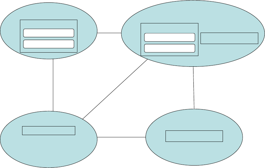
5-9
• Shared infrastructure: hardware, software, and virtual components that enable
service deployment,
• Information assurance, service management, network operations, etc.
Documenting these various aspects of net-centricity in the SV-1 products will show what
systems and services communicate with each other and support the operational nodes in the OV-
2, and provide the basis for more efficient distribution of information and capabilities to the
NCE.
Figure 5-8 provides a template of the internodal version of a net-centric SV-1, showing
system interfaces between nodes from node edge to node edge. Items shown to help illustrate
net-centricity include: 1) an Enterprise Service Bus (ESB), 2) systems deploying high-level
functional groupings of services [the boxes with rounded corners] and 3) a web-portal system.
Information identifying service consumers and providers could be attached as metadata to each
node. It is not necessary to depict individual services in this layer, as the sheer number of them
would quickly add to the complexity of the diagram. However, a high-level grouping of services
(service families) assists in identifying systems that may have large sets of services that may be
offered. Individual services within the service families may be decomposed in the net-centric
SV-4. Furthermore, the diagram illustrates that the same system may appear in different nodes,
but offer different sets of service functional groupings. This is meant to highlight the fact that a
system might offer a set of services to the NCE from different locations, but each set is still to be
considered part of the same system. Figure 5-8 introduces an illustration of ESB usage, with the
EIEMA location providing Core Enterprise Services.
Sensor System
Sensor
Deployment Location
ESB
EIEMA
Data Analysis
Location
Analysis System
Data
Processing Location
Web-Portal SystemWeb-Portal System
Data Service Family
Sensor Control Service Family
Sensor System
Data Service Family
Data Processing Service Family
Sensor System
Data Service Family
Data Processing Service Family
Figure 5-8: Notional Example: SV-1: Layer 1 Example
Figure 5-9 provides a template of the intranodal version of an SV-1, showing interfaces from
system-to-system, system-to-service, and service-to-service. Figure 5-9 is meant to provide an

5-10
example of a single diagram from a 2nd layer of SV-1s, which consists of a series of diagrams
decomposed from Figure 5-8. Figure 5-9 illustrates services and their connections from the
viewpoint of one node, the “Data Processing and Storage Location” node. Other 2nd layer SV-1
diagrams would be necessary to illustrate viewpoints from different nodes. The service families
appearing in Figure 5-8 are decomposed in Figure 5-9 to show the specific set of services hosted
at each node. Furthermore, Figure 5-9 highlights specific services provided by the ESB that are
used by the program’s owned systems and services. Note: Figure 5-9 is only an example of a
layered approach to SV-1. Other viewpoints, other than the example nodal-view, are possible.
The number of SV-1 layers will depend on the scope of the program’s architecture.
ESB
Data Processing
& Storage Location
Sensor
Deployment Location
EIEMA
Data Analysis
Location
Analysis System
Sensor System
Streaming Service
Data Service Family
Registration Service
Discovery Service
Service “N”
Web-Portal SystemWeb-Portal System
Sensor System
Data Service Family
Playback Service
Storage Service
Data Processing Service Family
Conversion Service
Validation Service
Sensor System
Data Service Family
Playback Service
Storage Service
Data Service Family
Playback Service
Storage Service
Data Processing Service Family
Conversion Service
Validation Service
Data Processing Service Family
Conversion Service
Validation Service
Figure 5-9: Notional Example: SV-1: Layer 2 Example
5.1.4 CADM Support for SV-1
SV-1 is stored as an instance of Document with its attribute ArchitectureProductTypeCode =
SYSTEM-INTERFACE-DESCRIPTION. To capture the information content of the SV-1 product in
CADM v1.5, each of its components (i.e., each specific interface) is linked to it via
ObjectVersionAssociation (see Volume III for details).
The specific system interfaces, in turn, can be expressed in CADM v1.5 in terms of links
between specific pairs of System
instances coupled to a specific TechnicalInterface. Where
required, the primary communications medium and relevant standards for the SV-1 can be
expressed in CADM v1.5, the latter via the entities InformationTechnologyStandard and
MessageStandard
. The attribute CategoryCode in InformationTechnologyStandard can be set to
PROTOCOL-STANDARD or INFORMATION-TECHNOLOGY-STANDARD-PROFILE, when one needs to
refer to those types of technical standards in connection with DoDAF product SV-1.
Each system referenced in SV-1 is identified and described by populating the entity System.
The set of System
instances addressed in the Systems and Services View of an Architecture can
5-11
be captured in CADM v1.5 by linking them through ObjectVersionAssociation. As noted in the
discussion of taxonomies (see AV-2 above), systems can also be related to other systems in
CADM v1.5. Classification of systems according to general classes can be done through the
entity SystemType. Finally, instances of Capability, DirectedConstraint, Document,
EquipmentType, InformationAsset, Organization, ProcessActivity, Satellite, SecurityClassification,
and SoftwareType can also be related to a given instance of System in CADM (not all of these
appear in Figure 5-10 provided below).
For some architectures, the operational requirements of equipment and subordinate
organizations for each OrganizationType depicted in (or described by) SV-1 may be of
fundamental importance. CADM v1.5 contains structures that can capture the information
content of Tables of Organization and Equipment (TOEs) – see Volume III for details.
Similarly, the Modified Tables of Organization and Equipment (MTOE) for an Organization
can be recorded in a CADM-structured database by linking the TOE to the instance of
Organization. All the TOEs (and MTOEs) applicable to a specific Architecture can be recorded
through the appropriate entries in ObjectVersionAssociation.
An SV-1 can apply to many architectures. This is expressible in CADM by establishing a
relationship between the instances of Architecture to that instance of Document. Any other
DoDAF system products related to SV-1 (such as SV-2, SV-3, and SV-4) can be linked to a
given SV-1 by populating establishing associations among Document instances.
Figure 5-10 provides a high-level diagram from the CADM showing key entities that are
used to store architecture data for SV-1 in a CADM-conformant database.

5-12
Figure 5-10: CADM Diagram for SV-1

5-13
5.1.4.1 SV-1 – Data Element Definitions
SV-1 Information Space
Agreement
†
Architecture
†
Document
†
IconCatalog
†
Materiel
†
MaterielType
†
MilitaryPlatform
†
Organization
†
Organization Type
†
Satellite
†
SoaOperation
†
SoaService
†
SoaServiceSpecificationTemplate
†
System
†
EquipmentType
InformationTechnologyStandard
SoftwareType
SystemType
TechnicalInterface
†)
The descriptions of these elements have been provided in the preceding sections
Table 5-1 describes the architecture data elements associated with SV-1.
Table 5-1: Data Element Definitions for SV-1
34
Data Elements Attributes Definition
EquipmentType
alternateIdentifierText The text for the identifier that alternatively represents a
specific EquipmentType.
cargoArea The area required to store the EquipmentType when
configured for transport.
cargoDescriptionText The free-form text describing the EquipmentType being
defined.
cargoHeightDimension The height dimension of the EquipmentType when
configured for transport.
cargoLengthDimension The length dimension of the EquipmentType when
configured for transport.
cargoVolume The volume of the EquipmentType when configured for
transport.
cargoWeight The weight of the EquipmentType when configured for
transport.
cargoWidthDimension The width dimension of the EquipmentType when
configured for transport.
makeName The name of the originator of a specific EquipmentType
modelSeriesIdentifier
Text
The text that identifies a specific manufacturer production
series for an EquipmentType.
peakPowerQuantity The quantity that represents the maximum electrical power
demanded under operation of a specific EquipmentType.
receiver-
transmitterQuantity
The quantity that represents the number of
receiver/transmitter units for a specific EquipmentType.
roleCategoryCode The code that denotes a class of use to which the
EquipmentType is commonly put.
InformationTechnology
Standard*
34
As noted earlier, data elements marked with an asterisk (*) should be included by the architecture development team, if the product is chosen
for development as part of an integrated architecture effort.

5-14
Data Elements Attributes Definition
categoryCode* The code that represents a class of
InformationTechnologyStandard.
criterionDescriptionText The text that characterizes the parameters against which an
InformationTechnologyStandard is to be evaluated.
designatorSource
AbbreviatedName
The shortened form of the name commonly used to specify
the standards body that promulgates a specific
InformationTechnologyStandard.
designatorSource
IdentifierText
The text that describes the identifier assigned by the source
standards body to a specific
InformationTechnologyStandard.
DevelopmentalStatus
Code
The code that represents the state of preparation of an
InformationTechnologyStandard.
layerCode The code that represents the predominant element of the
seven-layer open systems interconnection (OSI) reference
model that applies to a specific
InformationTechnologyStandard.
measureDescriptionText The text that characterizes how the
InformationTechnologyStandard is to be applied for
conformance.
profileTypeCode The code that represents a kind of profile for a specific
InformationTechnologyStandard.
projectSpecificCode The code that represents whether a specific
InformationTechnologyStandard is used only for a specific
implementation.
SoftwareType
buildIdentifierText The text that identifies a specific integration event for a
SoftwareType.
categoryCode The code that represents the class of a SoftwareType.
centralProcessingUnit
RequirementText
The text that represents the characteristics (e.g., speed) of a
central processing unit in order to satisfactorily operate the
SoftwareType.
commentText The text that amplifies information regarding a specific
SoftwareType.
commercialOffTheShelf
Code
The code that represents whether a specific SoftwareType
is available as a commercial off-the-shelf product.
complianceCode The code that represents the level of compliance of the
current version of a SoftwareType with the defense
information infrastructure (DII) common operating
environment (COE).
diskSpaceRequirement
Text
The text that describes the disk space required for a
SoftwareType.
executableLinesOfCode
Quantity
The quantity that represents the number of linear elements of
programming language, excluding comments, for a
SoftwareType.
governmentOffTheShelf
Code
The code that represents whether a specific SoftwareType
is available as a government-developed off-the-shelf product.
longName The complete (formal) name of a specific SoftwareType.
manufacturerName The name of the manufacturer of a SoftwareType.
maximumSimultaneous
UserQuantity
The quantity that represents the largest number of
simultaneous users for a specific SoftwareType.
memoryRequirement
Text
The text that describes the central processing unit memory
capacity required for the SoftwareType to function correctly.
outputFormat The text that summarizes the syntax used to export data for a

5-15
Data Elements Attributes Definition
DescriptionText specific SoftwareType.
releaseCalendarDate The calendar date a specific SoftwareType was distributed
for general use.
securityFeature
CommentText
The text that briefly characterizes the access control for a
specific SoftwareType.
subcategoryCode The code that represents a detailed classification of
SoftwareType.
versionChangeText The text that describes the differences in functionality
incorporated into the specific SoftwareType.
versionIdentifierText The text that identifies a specific release of the
SoftwareType.
SystemType
alternateIdentifierText The text that pertains to the identifier that is alternatively
used to specify a SystemType.
TechnicalInterface
commentText The text that provides additional information regarding a
specific TechnicalInterface.
importanceCode The code that represents whether a specific
TechnicalInterface has been determined to be crucial to a
mission capability.
statusCode The code that represents the state of a specific
TechnicalInterface.
Relationships
Parent Verb Phrase Child
Architecture
uses
IconCatalog
EquipmentType
is operated using
SoftwareType
EquipmentType
is used in
System
InformationTechnologyStandard
is cited for use in
MaterielType
InformationTechnologyStandard
uses
System
InformationTechnologyStandard
pertains to
TechnicalInterface
InformationTechnologyStandard
applies to
SoaService
MaterielType
identifies
EquipmentType
MaterielType
may be a
SoftwareType
Organization
is assigned
TechnicalInterface
Organization
is source for
SoftwareType
SoaService
uses
EquipmentType
SoaService
uses
SoftwareType
SoaService
uses
TechnicalInterface
SoftwareType
is provided for
EquipmentType
SoftwareType
is related to
SoftwareType
System
uses
SoftwareType
(All previous relationships for the listed entities that comprise the information space of SV-1 should be considered
part of the specification for this product, as well as those for the entities modeled via ObjectByReference and
ObjectVersionAssociation. For the latter, see Volume III.)
5-16
5.2 SYSTEMS AND SERVICES COMMUNICATIONS DESCRIPTION (SV-2)
5.2.1 SV-2 – Product Description
Product Definition. The SV-2 depicts pertinent information about communications systems,
communications links, and communications networks. SV-2 documents the kinds of
communications media that support the systems and implements their interfaces as described in
SV-1. Thus, SV-2 shows the communications details of SV-1 interfaces that automate aspects of
the needlines represented in OV-2.
Product Purpose. SV-2 can be used to document how interfaces (described in SV-1) are
supported by physical media. This kind of communications media support information is critical
in performing certain infrastructure and system acquisition decisions.
Product Detailed Description. SV-2 documents the specific communications links or
communications networks (e.g., Intelink or Joint Worldwide Intelligence Communications
System (JWICS)) and the details of their configurations through which systems interface. While
SV-1 depicts interfaces between systems or systems nodes, SV-2 contains a detailed description
of how each SV-1 interface is implemented (e.g., composing parts of the implemented interface
including communications systems, multiple communications links, communications networks,
routers, and gateways).
Communications systems (e.g., switches, routers, and communications satellites) are systems
whose primary function is to control the transfer and movement of system data as opposed to
performing mission application processing.
A communications link is a single physical connection from one system (or node) to another.
A communications path is a (connected) sequence of communications systems and
communications links originating from one system (or node) and terminating at another system
(or node).
A communications network may contain multiple paths between the same pair of systems.
The term interface used in SV-1 and referenced in SV-2 represents an abstraction of one or more
communications path(s).
The graphical presentation and supporting text for SV-2 should describe all pertinent
communications attributes (e.g., waveform, bandwidth, radio frequency, and packet or waveform
encryption methods). Communications standards are also documented in this product, where
applicable.
Because SV-2 depicts the implementation details for the interfaces described in SV-1 by
decomposing them into communications systems, communications links, and communications
networks, it can present either internodal or intranodal versions. The internodal version details
the communications links and/or communications networks that interconnect systems nodes
(node edge to node edge) or specific systems (system-system from one node to other nodes). The
intranodal version of SV-2 looks inside each of the represented nodes to illustrate the
communications links between specific systems.
Figure 5-11 provides a template for the internodal version of SV-2. Note that Figure 5-11
translates the single-line representations of interfaces (as shown in the SV-1 internodal version)
into an implementation detail of the communications infrastructure that provides the connections.
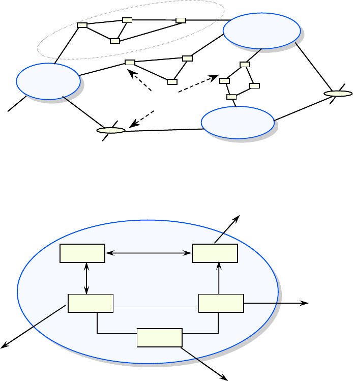
5-17
The small boxes in Figure 5-11 represent communications systems, as do the satellite icons. The
lines between the communications systems represent communications links and, together with
communications systems, can be organized into communications paths or networks.
NODE A
NODE B
NODE C
EXTERNAL
CONNECTION
(OUTSIDE THE NODES
OF INTEREST)
COMMUNICATIONS
LINKS, AND NETWORKS
DETAILS OF COMMS
INTERFACE 1
NODE A
NODE B
NODE C
EXTERNAL
CONNECTION
(OUTSIDE THE NODES
OF INTEREST)
COMMUNICATIONS
LINKS, AND NETWORKS
DETAILS OF COMMS
INTERFACE 1
Figure 5-11: Systems Communications Description, Internodal Version (SV-2) – Template
Figure 5-12 provides a template for the intranodal version of SV-2.
NODE A
Local Area Net
System 1
System 2
System 3
System 4
System 5
EXTERNAL
CONNECTION
(OUTSIDE THE
NODES OF INTEREST)
CONNECTION
TO NODE B
CONNECTION
TO NODE B
CONNECTION
TO NODE C
Two-Way
Communications
Links
One-Way
Communications
Link
NODE A
Local Area Net
System 1
System 2
System 3
System 4
System 5
EXTERNAL
CONNECTION
(OUTSIDE THE
NODES OF INTEREST)
CONNECTION
TO NODE B
CONNECTION
TO NODE B
CONNECTION
TO NODE C
Two-Way
Communications
Links
One-Way
Communications
Link
Figure 5-12: Systems Communications Description, Intranodal Version (SV-2) – Template
5.2.2 UML Representation
An effective way to develop SV-2 using the UML is with a class diagram. The class diagram
association stereotyped is <<connection>> and named to identify the communications medium.
Additionally, key interface elements further describe the relevant interface, its function and
related operational view component. For complex architectures, the architect may choose not to
depict interface elements and their underlying operational components.

5-18
IBC Server
post relevant information( : RelevantInformation)
IMIP Gateway
publish filtered relevant information( : RelevantInformation)
IJTCW
publish relevant information( : RelevantInformation)
External Information Recipient
Liaison Officer
Coallition MIP Gateway
JTCW
<<system>>
MIP Gateway LAN
<<connection>>
BC Server
WAN
<<connection>>
Information Source
Many Sources
<<connection>>
Battle Command Information System
<<system>>
Figure 5-13: UML Representation for SV-2
Because actors aggregate to operational nodes, this information is contained in the model.
For example, the Liaison Officer interacts with the JTCW; therefore, the JTCW belongs to the
same operational node as the Liaison Officer. This is a good example of the difference between
structured analysis and object-oriented technique. The two methods do not always map one-to-
one on all views; however, the related intent and model information is still applied.
5.2.3 Net-Centric Guidance SV-2
Augmented Product Purpose. In a net-centric architecture, the SV-2 is used to 1) detail the
communication paths used by the interfaces between services, systems, and system nodes, 2)
highlight critical communications infrastructure that is connecting to or shared with the NCE,
and 3) depict the physical mechanisms that host services provided to the NCE.
Net-Centric Product Description. The SV-2 traditionally documents the specific
communications links or communications networks and the details of their configurations
through which systems interface. Accordingly, in the NCE, the SV-2 contains a detailed
description of how each SV-1 interface is implemented and depicts communications systems,
links, protocols, standards, and networks that support the delivery of information and capabilities
to services and consumers in the NCE. It is important to note that in a net-centric SV-1 a system
node containing services should have interface lines that highlight the use of internet protocols
(i.e., HTTP, SOAP).
Services are a key means to share information and functionality in the NCE through
published service interfaces, as depicted in the SV-1, that enable interoperability among
applications across the NCE. The details of how the service interfaces are physically
implemented at the network layer can be captured in the SV-2 by depicting different views of the
communications layers between services. The SV-2 provides a more detailed communications
5-19
analysis and can be depicted in separate SV-2s to show different layers of the communications
network. For example, network layer messaging capabilities such as SOAP intermediary
message routers can be captured in the SV-2. As part of the net-centric SV-2, the DoD-wide SST
should be used to the extent possible for describing each service. Regardless of the precise SST,
the necessary minimum subset of information from the SST for each service must be captured in
the SV-2:
o Service Access Point Information Category includes information that describes the
message format and transmission protocol, URL, the operational status and point of
contact, and the lifecycle step of the service (i.e., development, testing, or
production).
This would include information about the host layer that depicts hosting
locations for services and lists the service implementations they are
hosting. Implementations that should be represented include offered
services that appear in the net-centric SV-1, enterprise service bus
components, and infrastructure services.
o Quality Model Category includes information on the security requirements of the
service, the QoS levels, and any performance considerations for service
deployment.
Service Level Specifications identify performance specification details that
stipulate expected service performance under identified circumstances and
quality of service levels. This would include information at the physical
layer that depicts physical components of communications channels
between known providers and consumers and should illustrate network
hops, bandwidth limits, and connectivity environment.
In addition to the SST elements, DoDAF v1.5 extends the service interface specifications, to
include a Service Provider element. The Service Provider element identifies the organization
providing the service (the organization that is the Service Functionality Provider operational role
from the OV-2).
Separate SV-2s that show different communications layers can assist in understanding and
depicting the complexity of the interoperability among applications and services across the NCE.
The different depictions of the SV-2 should be linked among different layers to provide program
managers a high-level view of the communications infrastructure.
Documenting these various aspects of net-centricity in the SV-2 products will describe
service requirements on the capacity, timing, and reliability of services composing the
architecture.
Figure 5-14 illustrates an intranodal version of a net-centric SV-2 from the viewpoint of a
single node that appears in the net-centric example SV-1. In this example, the single interface

5-20
Data
Processing Location
Web-Portal SystemWeb-Portal System
Sensor System
Data Service Family
Playback Service
Storage Service
Data Processing Service Family
Conversion Service
Validation Service
Sensor System
Data Service Family
Playback Service
Storage Service
Data Service Family
Playback Service
Storage Service
Data Processing Service Family
Conversion Service
Validation Service
Data Processing Service Family
Conversion Service
Validation Service
TERRESTRIAL CONNECTION
TO DATA ANALYSIS
LOCATION NODE
TERRESTRIAL CONNECTION
TO EIEMA
LOCATION NODE
SATELLITE CONNECTION
TO SENSOR DEPLOYMENT
LOCATION NODE
TERRESTRIAL CONNECTION
TO SENSOR DEPLOYMENT
LOCATION NODE
Enterprise Service Bus (ESB)
Figure 5-14: Notional Example: SV-2: Layer 2 Example
appearing in the net-centric SV-1 notional example between the Data Service Family’s Storage
Service in the Data Processing Location and the Data Service Family’s Streaming Service in the
Sensor Deployment location is supported by two communications paths, a satellite connection
and a terrestrial connection. Also highlighted are interfaces to locally hosted ESB components,
which provide service related messaging and transport mechanisms internal to the node.
Specifics on communications networks and protocols should be attached as metadata to each
communication path.
5.2.4 CADM Support for SV-2
SV-2 is stored as an instance of Document with its attribute ArchitectureProductTypeCode =
SYSTEM-COMMUNICATION-DESCRIPTION. To capture the information content of the SV-2
product in CADM v1.5, each of its components are linked to it via ObjectVersionAssociation (see
Volume III for details). The subject of each SV-2 is a set of Node instances and their associations
defined as a specific Network. In CADM v1.5, instances of the entity Network can be linked to
Capability, System, and InformationTechnologyStandard. The link to Capability serves to record
quantifiable measures of performance (MOPs) for components of the Network.
Additional characteristics cited for a specific SV-2 are specified using the following entities,
as applicable:
• CommunicationMedium
• EquipmentType (a subset of MaterielType)
• Materiel and its associations to other instances of Materiel, as well as associations
to Organization
• SoftwareType
5-21
Nodal diagrams prepared for SV-2 can also be linked to IconCatalog in the CADM to
associate graphical representations to the content of SV-2, and enable, for example, the
specification of which fields shall be presented when users highlight (click) an icon. To that
effect, the attribute NodeIconCategoryCode in IconCatalog can be set to
LINK-ICON or NODE-
ICON
.
In CADM v1.5 Network can be linked to Architecture, Node, other instances of Network,
Capability, CommunicationMedium, Organization, and NetworkType. Each Node can be related to
other instances of Node as well as any of the following entities as required:
ActivityModelInformationElementRole, CommunicationMedium, DataItemType, Capability,
Organization, OrganizationType, ProcessActivity, System, and Task (not all are shown in Figure
5-15).
SV-2 can be populated with electronic addresses for each fielded communications device by
linking them to instances of the entity ObjectByReference with its CategoryCode =
INTERNET-
ADDRESS
.
Because many other CADM entities involved in SV-2 are the same as for SV-1, their
discussion is not repeated here.
Figure 5-15 provides a high-level diagram from the CADM showing key entities that are
used to store architecture data for SV-2 in a CADM-conformant database.

5-22
Figure 5-15: CADM Diagram for SV-2
5.2.4.1 SV-2 – Data Element Definitions
SV-2 depicts the implementation of the interfaces from SV-1 as specific communications
systems, communications links, communications paths, or communications networks and the
details of their configurations through which the systems interface. Table 5-2 describes the
architecture data elements associated with SV-2.

5-23
SV-2 Information Space
Agreement
†
Architecture
†
Capability
†
CapabilityCategory
†
CommunicationMedium
†
Document
†
EquipmentType
†
Facility
†
IconCatalog
†
InformationTechnologyStandard
†
Materiel
†
MaterielType
†
Network
†
NetworkType
†
Node
†
Organization
†
OrganizationType
†
PointOfContact
†
SoaOperation
†
SoaService
†
SoaServiceSpecificationTemplate
†
SoftwareType
†
System
†
SystemType
†
MessageStandard
†)
The descriptions of these elements have been provided in the preceding sections
Table 5-2 Data Element Definitions for SV-2
Data Elements Attributes Definition
MessageStandard
categoryCode The code that represents a class of MessageStandard.
formatCode The code that represents a kind of MessageStandard
format.
lastRevisionCalendar
Date
The calendar date of last change of the MessageStandard
as approved for information system usage.
referenceIdentifierText The text to describe the identifier of the MessageStandard
as cited for its message set.
transactionTable
GenerationName
The name that represents the physical source of a
transaction for a specific MessageStandard.
transactionUsageName The name that represents the primary employment of a
transaction for a specific MessageStandard.
Relationships
Parent Verb Phrase Child
PointOfContact
is cited for
SoaServiceSpecificationTemplate
(All previous relationships for the listed entities that comprise the information space of SV-2 should be considered
part of the specification for this product, as well as those for the entities modeled via ObjectByReference and
ObjectVersionAssociation. For the latter, see Volume III.)

5-24
5.3 SYSTEMS-SYSTEMS, SERVICES-SYSTEMS, SERVICES-SERIVCES
MATRICES (SV-3)
5.3.1 SV-3 – Product Description
Product Definition. The SV-3 provides detail on the interface characteristics described in
SV-1 for the architecture, arranged in matrix form.
Product Purpose. SV-3 allows a quick overview of all the interface characteristics presented
in multiple SV-1 diagrams. The matrix form can support a rapid assessment of potential
commonalities and redundancies (or, if fault-tolerance is desired, the lack of redundancies).
SV-3 can be organized in a number of ways (e.g., by domain, by operational mission phase)
to emphasize the association of groups of system pairs in context with the architecture purpose.
SV-3 can be a useful tool for managing the evolution of systems and system infrastructures, the
insertion of new technologies/functionality, and the redistribution of systems and processes in
context with evolving operational requirements.
Product Detailed Description. SV-3 is a summary description of the system-system
interfaces identified in SV-1. SV-3 is similar to an N
2
-type matrix, where the systems are listed
in the rows and columns of the matrix, and each cell indicates a system pair interface, if one
exists. Many types of interface information can be presented in the cells of SV-3. The system-
system interfaces can be represented using a number of different symbols and/or color codes that
depict different interface characteristics. The following are examples:
• Status (e.g., existing, planned, potential, deactivated)
• Purpose (e.g., C2, intelligence, logistics)
• Classification level (e.g., SECRET, TS/SCI)
• Means (e.g., JWICS, Secret Internet Protocol Router Network (SIPRNET))
• Standard
• Key Interface
Figure 5-16 provides a template for SV-3. Each cell may contain several interface
characteristics, but this is not shown in the notional example provided below.
SYSTEM
1
z
zzzzz
zzzz
zz zz
zzz z
zzzzz zzzz
z
z
z
z
SYSTEM
2
SYSTEM
3
SYSTEM
4
SYSTEM
5
SYSTEM
6
SYSTEM
7
SYSTEM
8
SYSTEM
9
SYSTEM
10
SYSTEM 1
SYSTEM 2
SYSTEM 3
SYSTEM 4
SYSTEM 5
SYSTEM 6
SYSTEM 7
SYSTEM 10
SYSTEM 8
SYSTEM 9
SYSTEM
1
z
zzzzz
zzzz
zz zz
zzz z
zzzzz zzzz
z
z
z
z
SYSTEM
2
SYSTEM
3
SYSTEM
4
SYSTEM
5
SYSTEM
6
SYSTEM
7
SYSTEM
8
SYSTEM
9
SYSTEM
10
SYSTEM 1
SYSTEM 2
SYSTEM 3
SYSTEM 4
SYSTEM 5
SYSTEM 6
SYSTEM 7
SYSTEM 10
SYSTEM 8
SYSTEM 9
Figure 5-16: SV-3 – Template
5.3.2 UML Representation
There is no equivalent to this product in UML. Row and column headings should trace to
systems of SV-1 (and SV-2).

5-25
5.3.3 Net-Centric Guidance for SV-3
Augmented Product Purpose. In a net-centric architecture, the SV-3 is used to capture
service interactions, dependencies, and interface characteristics presented in the SV-1(s). The
net-centric SV-3 highlights the services that the subject architecture is providing to the NCE, the
services that the subject architecture is consuming from the NCE, and the dependencies between
both.
Net-Centric Product Description. The SV-3 traditionally provides a summary description
of the system-system interfaces identified in the SV-1. Accordingly, in the NCE, the SV-3
should also provide two additional summary products:
• Services-Systems Matrix to highlight 1) consuming non-SOA systems of the
program interfacing with internal or external services obtained from the NCE,
and 2) services provided interfacing with known internal or external NCE
Service Consumers
• Services-Services Matrix to highlight services provided that interface with
internal or external services obtained from the NCE (those relating to
infrastructure are one example)
The Services-Systems Matrix and the Services-Services Matrix may provide a layer of detail
under a higher level Systems-Systems Matrix if the systems concerned are decomposable into
lower level services.
In the NCE, services are a key means to share information in the NCE, and are defined and
captured in the SV-4 and SV-1. Services make information and capabilities available in the NCE
through published service interfaces that define the message exchange between the service
provider and service consumer, and enable interoperability among applications across the NCE.
Documenting services-services interfaces in the SV-3 for a net-centric program will provide a
quick overview of how services are being leveraged (i.e., the extent of net-centricity) and the
service dependencies associated with delivering the systems capability. It also provides for a
rapid assessment of commonalities and redundancies.
5.3.4 CADM Support for SV-3
SV-3 is stored as an instance of Document with its attribute ArchitectureProductTypeCode =
SYSTEM-SYSTEM-MATRIX. The matrix is built via ObjectVersionAssociation, which links each of
the components to the instance of SV-3. In CADM v1.5, it is also possible to capture semantics
of Provider System and Recipient System. Provider System and Recipient System are related to
each other in a CADM-structured database as one or more instances ObjectVersionAssociation.
Further characterization of both the service-to-service and the system-to-system associations,
e.g., communication means and constraints are also possible (see Volume III for details).
Figure 5-17 provides a high-level diagram from the CADM showing key entities that are
used to store architecture data for SV-3 in a CADM-conformant database.
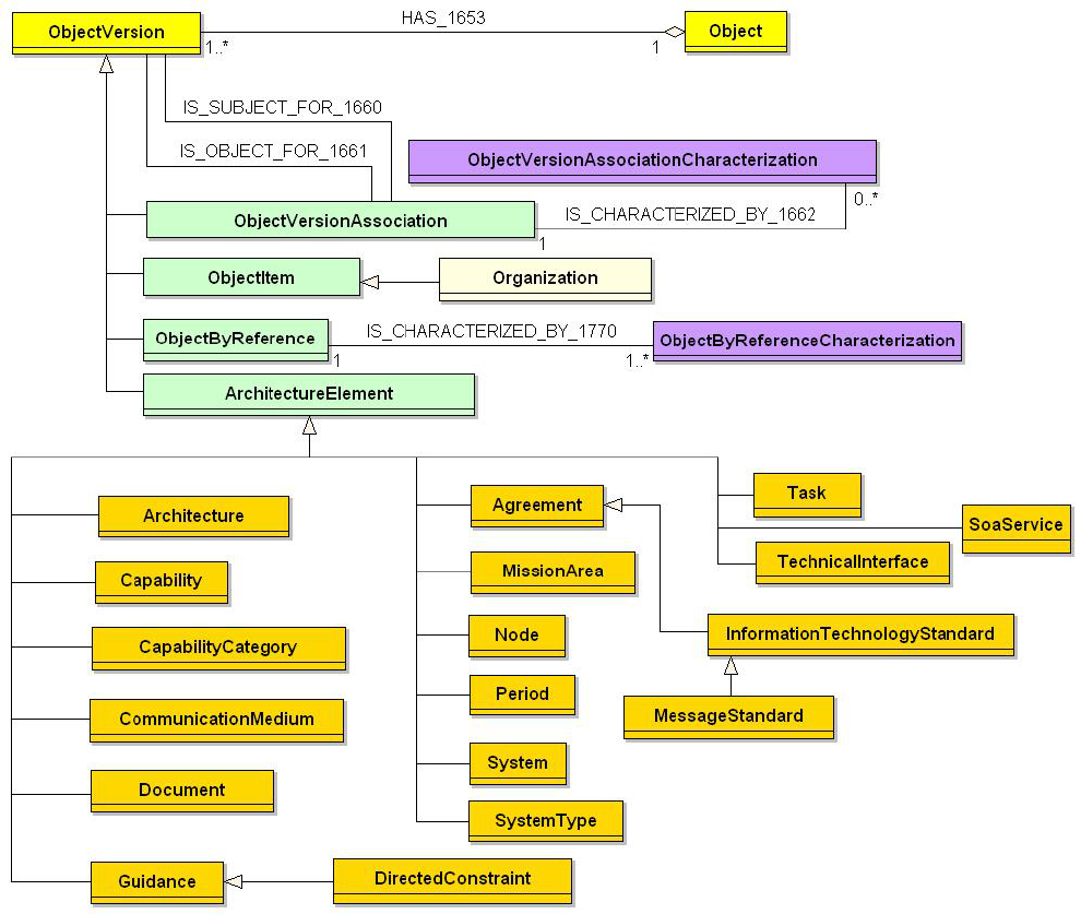
5-26
Figure 5-17: CADM Diagram for SV-3
In addition to the SV-3 linkages mentioned above, it is also possible to relate SV-3 to:
• Agreement (and its subtype InformationTechnologyStandard). The latter can be
further specialized via its categoryCode. Possible values are: MESSAGE-
STANDARD, PROTOCOL-STANDARD,
and INFORMATION-TECHNOLOGY-
STANDARD-PROFILE.
• SecurityClassification
• CommunicationMedium
• DirectedConstraint (a subtype of Guidance)
Linkage to SystemStatusType can be used to specify the status of systems that make up the
SV-3. Details for each Provider System and Receiver System can also be captured (e.g., via the
entity SystemType). SV-3 can be related to Architecture by the appropriate relationship of that
instance of Document to Architecture in ObjectVersionAssociation. This allows the reuse of an

5-27
SV-3 in multiple architectures. The SV-3 can be related to other SV products such as SV-1, SV-
2, and SV-4 by establishing the appropriate links to those instances of Document.
5.3.4.1 SV-3 – Data Element Definitions
SV-3 Information Space
Agreement
†
Architecture
†
Capability
†
CapabilityCategory
†
CommunicationMedium
†
Document
†
Guidance
†
InformationTechnologyStandard
†
MessageStandard
†
MissionArea
†
Node
†
Organization
†
Period
†
SoaService
†
System
†
SystemType
†
Task
†
TechnicalInterface
†
DirectedConstraint
†)
The descriptions of these elements have been provided in the preceding sections
Table 5-3 defines the architecture data elements for SV-3.
Table 5-3: Data Element Definitions for SV-3
Data Elements Attributes Definition
DirectedConstraint
requirementCode The code that represents whether a specific
DirectedConstraint is required.
statusCode The code that denotes the state of a specific
DirectedConstraint.
typeCode The code that represents a kind of a specific
DirectedConstraint.
Relationships
Parent Verb Phrase Child
System
has
DirectedConstraint
(All previous relationships for the listed entities that comprise the information space of SV-3 should be considered
part of the specification for this product, as well as those for the entities modeled via ObjectByReference and
ObjectVersionAssociation. For the latter, see Volume III.)

5-28
5.4 SYSTEMS AND SERVICES FUNCTIONALITY DESCRIPTION (SV-4A AND 4B)
5.4.1 Systems Functionality Description (SV-4a) – Product Description
Product Definition. The SV-4a documents system functional hierarchies and system
functions, and the system data flows between them. The SV-4 from DoDAF v1.0 is designated as
'SV-4a' in DoDAF v1.5. Although there is a correlation between OV-5 or business-process
hierarchies and the system functional hierarchy of SV-4a, it need not be a one-to-one mapping,
hence, the need for the Operational Activity to Systems Function Traceability Matrix (SV-5a),
which provides that mapping.
Product Purpose. The primary purposes of SV-4a are to 1) develop a clear description of the
necessary system data flows that are input (consumed) by and output (produced) by each system,
2) ensure that the functional connectivity is complete (i.e., that a system’s required inputs are all
satisfied), and 3) ensure that the functional decomposition reaches an appropriate level of detail.
Product Detailed Description. SV-4a describes system functions and the flow of system
data among system functions. It is the SV counterpart to OV-5. SV-4a may be represented in a
format similar to data flow diagrams (DFDs) [DeMarco, 1979]. The scope of this product may be
enterprise wide, without regard to which systems perform which functions, or it may be system
specific. Variations may focus on intranodal system data flow, internodal system data flow,
system data flow without node considerations, function to system allocations, and function to
node allocations.
The system functions documented in the SV-4a may be identified using the Service
Component Reference Model (SRM),
35
or some other system function taxonomy, and correlated
to SV-1 and SV-2 systems. System functions are not limited to internal system functions and can
include Human Computer Interface (HCI) and Graphical User Interface (GUI) functions or
functions that consume or produce system data from/to system functions that belong to external
systems. The external system data sources and/or sinks can be used to represent the human that
interacts with the system or external systems. The system data flows between the external system
data source/sink (representing the human or system) and the HCI, GUI, or interface function can
be used to represent human-system interactions, or system-system interfaces. Standards that
apply to system functions, such as HCI and GUI standards, are also specified in this product.
Like OV-5, SV-4a may be hierarchical in nature and may have both a hierarchy or
decomposition model and a system data flow model. The hierarchy model documents a
functional decomposition. The functions decomposed are system functions. Figure 5-18 shows a
template for a functional decomposition model of SV-4a.
35
The SRM is one of the reference models associated with the Federal Enterprise Architecture.

5-29
FUNCTION 1
SUBFUNCTION
11
SUBFUNCTION
13
SUBFUNCTION
12
SUBFUNCTION
121
SUBFUNCTION
122
FUNCTION 1
SUBFUNCTION
11
SUBFUNCTION
13
SUBFUNCTION
12
SUBFUNCTION
121
SUBFUNCTION
122
Figure 5-18: SV-4a – Template (Functional Decomposition)
SV-4a documents system functions, the flows of system data between those functions, the
internal system data repositories or system data stores, and the external sources and sinks for the
system data flows. It may represent external systems or the humans that interact with the system
function. External sources and sinks represent sources external to the diagram scope but not
external to the architecture scope. Figure 5-19 shows a template for the DFD of SV-4a. The
ovals represent system functions at some consistent level of decomposition, the squares are
external system data sources and sinks, and the arrows represent system data flows. Internal
system data repositories are represented by parallel lines. SV-4a(s) can be arranged
hierarchically, with each system function at the parent level being decomposed into a child SV-
4a at the next level.
System
Function 1
DATA
REPOSITORY
DATA
FLOW 1
DATA
FLOW 2
DATA
FLOW 3
DATA
FLOW 4
DATA
FLOW 5
DATA
FLOW 6
DATA
FLOW 7
DATA
FLOW 8
DATA
FLOW 9
DATA
FLOW 10
EXTERNAL
SOURCE 1
EXTERNAL
SOURCE 2
EXTERNAL
SINK 1
EXTERNAL
SINK 2
System
Function 3
System
Function 4
System
Function 2
System
Function 1
DATA
REPOSITORY
DATA
FLOW 1
DATA
FLOW 2
DATA
FLOW 3
DATA
FLOW 4
DATA
FLOW 5
DATA
FLOW 6
DATA
FLOW 7
DATA
FLOW 8
DATA
FLOW 9
DATA
FLOW 10
EXTERNAL
SOURCE 1
EXTERNAL
SOURCE 2
EXTERNAL
SINK 1
EXTERNAL
SINK 2
System
Function 3
System
Function 4
System
Function 2
Figure 5-19: SV-4a – Template (Data Flow Diagram)
5.4.2 UML Representation
Use cases, classes, and class operations may be used to represent system or service functions
in SV-4. Use case diagrams are used to model the interactions between humans, external
systems, system functions, services, and service functions (use cases) within the scope of the
diagram. Systems use cases may be identified as a refinement of the operational use cases (they
have an <<include>> relationship with the operational use cases), and they represent the
automated portions of those use cases representing operational activities from OV-5. Actors in

5-30
systems use case diagrams may represent a mix of both the humans supported by the system
functions (correspond to those in OV-5 use case diagrams), and other systems external to the
system being described but not necessarily external to the architecture. They are the equivalent
of external sources and sinks in DFD notation. In addition, class diagrams are used to show static
relationships between system functions. These diagrams collectively describe the systems or
services support to the operational activities and operational use cases modeled in OV-5. Figure
5-20 is a sample SV-4 template of a UML use case diagram.
Systems Use Case 2
Human Role A
Systems Use Case 1
Human Role B
Systems Use Case 3
External System
Source
External System
Sink
Figure 5-20: UML Use Case Diagram for SV-4
The systems’ use cases and their relationships represented in this diagram should trace to the
operational activities and operational use cases represented in OV-5 and to the systems identified
in SV-1 and SV-2. The mapping between OV-5 to SV-4 use cases is not one to one; it is
normally many to many going both ways. For those automated OV-5 operational activities, the
operational activity maps to one or more systems use case(s) and to the realizations of the
systems use cases via classes and class operations. SV-4 systems use cases depict system
functional requirements, and actors represent entities that interface with the system functions.
Use case diagrams and class diagrams can be used to show system functional requirements
(use cases) and system functions (classes and class operations that realize the use cases). Class
diagrams are intended to model the static design perspective of an automated system. As SV-4
products, the classes represent the design perspective of the systems identified in SV-1 that
execute the system functions. Attributes and operations for these classes (that show associated
system data types and their permissible operations) may be specified or left out depending on the
level of implementation detail needed. Packages and containment relationships can be used in
conjunction with use case and class diagrams to show functional decomposition. Figure 5-21
depicts relationships between SV-4a use cases and the collection (packages) of classes that
implement them.

5-31
Systems Use Case 1
Package 3
Package 2
implemented by
implemented by
Class 1
(from Package 2)
Package 1
implemented by
Class 2
(from Package 2)
uses
Class 4
(from Package 2)
uses
Class 3
(from Package 2)
uses
uses
Systems Use Case 1
Package 3
Package 2
implemented by
implemented by
Class 1
(from Package 2)
Package 1
implemented by
Class 2
(from Package 2)
uses
Class 4
(from Package 2)
uses
Class 3
(from Package 2)
uses
uses
Figure 5-21: UML Class Diagram for SV-4a
Along with the system use case diagram, the system sequence diagram Figure 5-22 also
represents a good presentation of SV-4. This diagram depicts all the operations and related
objects processed by the system component. In concert with the UML SV-2, which defines the
communications <<connect>> type, the sequence diagram describes the patterns of behavior
(functions) between the system elements to complete the desired result of value to the end actor.
: Information
Source
: Information
Source
: BC Server : BC Server : Coallition MIP
Gateway
: Coallition MIP
Gateway
: JTCW : JTCW : Liaison Officer : Liaison Officer
1: post relevant information( : RelevantInformation)
4: publish relevant information( : RelevantInformation)
5: monitor situation
6: filter and mediate relevant information
3: implement subscription policy
2: post update process
7: publish filtered relevant information( : RelevantInformation)
Figure 5-22: Sequence Diagram
5-32
5.4.3 Net-Centric Guidance for SV-4b
Augmented Product Purpose. In a net-centric architecture, the SV-4b is used to document
service functionality that is exposed to the NCE, their respective grouping into service families,
and their service specifications. It is the SV counterpart to OV-5. Although there is a correlation
between OV-5 or business-process hierarchies and the service functional hierarchy of SV-4b, it
need not be a one-to-one mapping, hence, the need for the Operational Activity to Services
Traceability Matrix (SV-5c), which provides that mapping.
Net-Centric Product Description. The SV-4a traditionally describes system functions and
the flow of system data between functions and correlated to SV-1 and SV-2 systems. In the NCE,
the SV-4b should capture and depict how services are orchestrated together to deliver
functionality associated with an operational need. In industry, this is often referred to as
composeable applications.
Services are a key means to share information and capabilities in the NCE and can be
captured in the SV-4b by relevant service groupings or families to assist in understanding how a
set of services align with an operational domain or a system capability. The SV-4b also
documents the data flows between services and may represent external services, systems, or
humans that interact with the service. Multiple SV-4b products can be utilized to show deeper
levels of detail as system nodes are decomposed into service families which further decompose
into services that consist of specific operations and data.
In the NCE, services require robust and consistent descriptions to operate in the NCE where
service capabilities are discoverable and able to be consumed in a scalable and flexible manner.
The SV-4b should capture and depict information about each service that collectively represents
the service specification. A service specification should be provided for each service that is or
will be provided to the NCE. The service specification enables services to be documented in a
consistent manner, and the DoD-wide SST should be used to the extent possible for describing
each service. Regardless of the precise SST, the necessary minimum subset of information from
the SST for each service must be captured in the SV-4b:
- Interface Model Category includes information of the service specification that
identifies the service and enables service consumers to discover the service and
determine the service’s suitability for their needs. It also provides assistance in the
usage of the service, and includes service policies and the following types of
attributes:
o Service Name is a short descriptive name for the service to be provided and
as it appears in the SV-1.
o Service Version identifies the latest revision level of the service.
o Service Description is a textual narrative that describes the service offering
and its purpose.
- Service Access Point Information Category includes information of the service
specification that identifies the lifecycle step of the service:
o SAP Type identifies the lifecycle phase of the capability (e.g., Development,
Testing, or Production).

5-33
- Information Model Category includes information of the service specification that
identifies the data types that are used to interact with the service.
o Data Types refers to the URI that points to documentation of complex data
types and data structures that are used.
- Point Of Contact Information Category includes information on the types of
contacts associated with a service, which may include developers, managers, or
maintenance organizations.
- Service Access Point Information Category includes technology implementation
details that identify the physical infrastructure the service is or can be deployed
upon including hardware, software, message transport, and facilities. It is here (vs.
the SV-1) where the transport binding details for the message exchange between
services are captured (i.e., SOAP over HTTP, IDL over binary, XML over HTTP).
- Quality Model Category includes information on any performance considerations
for service deployment.
o Service Level Specifications identifies performance specification details
that stipulate expected service performance under identified circumstances
and quality of service levels.
In addition to the SST elements, DODAF v1.5 extends the service interface specifications to
include a Service Provider element. The Service Provider element identifies the organization
providing the service (the organization that is the Service Functionality Provider operational role
from the OV-2).
For the Information Model Category of the SST, DoDAF v1.5 also extends the minimum set
of information to include the following attributes:
- Overview identifies the attributes that include the name of the operation, a narrative
that describes the operation, and the message Flow Pattern.
- Effects refer to the results that may come from invoking the operation.
- WSDL is the URI that points to a file that is composed of a bundle of other files
including a WSDL and any supporting files for that WSDL.
Additional elements from the service specification categories are identified and documented
within other architecture views, resulting in an integrated view of the service specification across
architecture products.
As programs develop their SV-4s to document functions and services for systems, it may be
difficult to distinguish between a service and a system function. Producing separate SV-4
products for system functions and services may enable the delineation between the two,
particularly in hybrid environments. A new SV-4 product, the
Service Function Decomposition
only depicts the services decomposition, while maintaining compatibility of the SV-4 that
depicts system functions.
Figure 5-23 shows a template for the functional decomposition model for services of a net-
centric SV-4b. It illustrates a hierarchy of services, with a high-level service or service family
representation at its top. If the higher-level representation is a service family, services underneath
it are those that are grouped into the service family. If the higher-level representation is an

5-34
individual service, the services below it are one that the higher-level service orchestrates to
produce other functionality. Higher-level services or individual services may be represented in
the SV-1 and may be mapped to services one-to-one or decomposed in the SV-4b. Points to note
about the SV-4b are: 1) services may or may not be grouped into a service family 2) services can
be decomposed into other services which are orchestrated together to provide other functionality,
3) Multiple SV-4b’s can be used to highlight different service families or different orchestrations
of services.
Service/Service Family
Service 3Service 1 Service 2
Service 21 Service 22
Service/Service Family
Service 3Service 1 Service 2
Service 21 Service 22
Figure 5-23: Notional Example: SV-4b: Functional Decomposition
Figure 5-24 shows a template for the Data Flow Diagram for services of a net-
centric SV-4b. The ovals represent services, the squares are external system data sources and
sinks, and the arrows represent the direction of the system data flows. The template illustrates
exchanges between services internal to a view, between services internal to a view and services
external to it, and services internal to a view and a web-portal external to it.

5-35
Service 1
Service 3
Service 2
Service 4
External System 1
Data Flow 1
Data Flow 2
Data
Flow 3
External Service 1
Data Flow 4
External Portal 1
Data
Flow 5
Data
Flow 6
Data
Flow 7
Data
Flow 8
Data Flow 9
Figure 5-24: Notional Example: SV-4b: Data Flow Diagram
5.4.4 CADM Support for Systems and Services Functionality Description (SV-4)
SV-4 is stored as an instance of Document with its attribute ArchitectureProductTypeCode =
SYSTEM-FUNCTIONALITY-SPECIFICATION. SV-4s can be specified by using the same entities and
attributes as for ActivityModel. The specification of the activity model is thus stored as an
instance of InformationAsset with a category code designating it as an ActivityModel (a subtype of
InformationAsset). The key entities associated with defining system functions and their
relationships to ActivityModel are shown in Figure 5-25.

5-36
Figure 5-25: CADM Diagram for SV-4
SV-4 can be related to Architecture by the appropriate relationship of that instance of
Document to Architecture in ObjectVersionAssociation. This allows the reuse of an SV-4 in
multiple architectures. The SV-4 can be related to other SV products such as SV-1, SV-2, and
SV-3 by establishing the appropriate links to those instances of Document.
5-37
Each function and subfunction cited in the ActivityModel for a SV-4 is stored as an instance of
ProcessActivity with its categoryCode = SYSTEM-FUNCTION. A parallel description in terms of
family of services, services and service operations is also possible. The relation between
instances of ActivityModel and ProcessActivity, as well as between ProcessActivity and
SoaService are established via ObjectVersionAssociation. Hierarchical breakdowns of the
functions, as well as the SOA services in a specific SV-4, is done in a similar fashion (see
Volume III for details). Note that the hierarchical breakdowns can be specific to an SV-4 even if
one is dealing with the same system functions or SOA services.
In CADM v1.5, it is possible to specialize ProcessActivity to indicate that a system function
specifies the source or destination (sink) of an information flow in the form of an information
repository. This construct is not found in IDEF0 activity modeling but has been incorporated in
the CADM as an additional specialization of ProcessActivity. In addition, where the level of
granularity in the SV-4 requires having an explicit source and destination for every information
flow, the attribute categoryCode in ProcessActivity can be set to: (1) Start State/Condition and (2)
End State/Condition. These same two values can also used to identify an external source
ProcessActivity (start condition) and an external sink ProcessActivity (end condition) when they
are not considered data stores.
The information flows and their component information flows cited in the ActivityModel for a
SV-4 are stored as instances of InformationElement, and their roles in the SV-4 are stored as
instances of ActivityModelInformationElementRole. As noted in the discussion for OV-5, the
decomposition of an InformationElement into its components is also possible in CADM v1.5
through ObjectVersionAssociation. (Such decomposition could be viewed as not dependent on the
activity model or on the activities specified in the activity model. However, it is expected to be
consistent across activity models.)
As mentioned above, each InformationElement occurs in a SV-4 for a specific function. Their
roles (input and output) are expressed via the entity ActivityModelInformationElementRole. Note
that these roles are in relation to a specific ProcessActivity that forms part of the ActivityModel for
an SV-4.
When building a SV-4 all the additional details of the instances of InformationElement and
ProcessActivity, together with associations between them, may be populated so that the system
functions and information flows required for SV-5 and SV-6, respectively, are available for cross
reference. In CADM v1.5, links for instances of ProcessActivity (specialized as
SYSTEM-
FUNCTION
), can be established for the purpose of recording the cross references of system
functions to other instances of ProcessActivity.
To satisfy key operational requirement instances of ProcessActivity (specialized as SYSTEM-
FUNCTION
), they can be related in CADM v1.5 to Task instances. When external documentation
is cited for details of an ActivityModel (or other subtypes of InformationAsset) defined in a SV-4
the pertinent instances of Document can also be linked (see Volume III for details). Similarly,
CADM provides the necessary functionality to store relationships among system functions and
human factors, as well as lines of business.

5-38
5.4.4.1 SV-4 – Data Element Definitions
SV-4 Information Space
ActivityModel
†
ActivityModelInformationElementRole
†
Agreement
†
Architecture
†
Document
†
HumanBehaviorTask
†
InformationAsset
†
InformationElement
†
LineOfBusiness
†
MissionArea
†
OperationalRole
†
PointOfContact
†
ProcessActivity
†
ReferenceModel
†
SoaOperation
†
SoaService
†
SoaServiceSpecificationTemplate
†
System
†
Task
†
†)
The descriptions of these elements have been provided in the preceding sections
5-39
5.5 OPERATIONAL ACTIVITY TO SYSTEMS FUNCTION, ACTIVITY TO
SYSTEMS, AND ACTIVITY TO SERVICES TRACEABILITY MATRICES (SV-
5A, 5B, AND 5C)
5.5.1 Operational Activity to Systems Function and Activity to Systems Traceability
Matrix (SV-5a and b) – Product Description
Product Definition. Operational Activity to SV-5a and SV-5b is a specification of the
relationships between the set of operational activities applicable to an architecture and the set of
system functions applicable to that architecture. The SV-5 and extension to the SV-5 from
DoDAF v1.0 is designated as 'SV-5a' and ‘SV-5b’ in DoDAF v1.5 respectively.
Product Purpose. SV-5a depicts the mapping of operational activities to system functions
and thus identifies the transformation of an operational need into a purposeful action performed
by a system.
SV-5a can be extended (SV-5b) to depict the mapping of capabilities to operational activities,
operational activities to system functions, system functions to systems, and thus relates the
capabilities to the systems that support them. Such a matrix allows decision makers and planners
to quickly identify stovepiped systems, redundant/duplicative systems, gaps in capability, and
possible future investment strategies all in accordance with the time stamp given to the
architecture. SV-5b correlates capability requirements that would not be satisfied if a specific
system is not fielded to a specific DoD unit.
Product Detailed Description. The Framework uses the terms activity in the OVs and
function in the SVs to refer to essentially the same kind of thing—both activities and functions
are tasks that are performed, accept inputs, and develop outputs. The distinction lies in the fact
that system functions are executed by automated systems, while operational activities describe
business operations that may be conducted by humans, automated systems, or both. Typical
systems engineering practices use both of these terms, often interchangeably. However, given the
Framework’s use of activities on the operational side and functions on the systems side, and the
fact that operational nodes do not map one-to-one to systems nodes, it is natural that operational
activities do not map one-to-one to system functions. Therefore, SV-5b forms an integral part of
the eventual complete mapping from operational capabilities to systems requirements. SV-5 is an
explicit link between the OV and SV. The capabilities and activities are drawn from OV-5a, OV-
6b, and OV-6c. The system functions are drawn from an SV-4. (SV-1 and SV-2 may also define
system functions for identified systems.)
The relationship between operational activities and system functions can also be expected to
be many-to-many (i.e., one operational activity may be supported by multiple system functions,
and one system function may support multiple operational activities). Figure 5-26 provides a
notional example of SV-5a.

5-40
1
1.1
1.1.1
1.1.1.1
1.1.1.2
1.1.1.3
1.1.2
1.1.2.1
1.1.2.2
1.1.2.3
1.1.3
1.1.3.1
1.1.3.2
1.1.3.3
1.1.3.4
3.11
3.11.3
3.12
3.12.1
3.12.2
3.12.3
3.13
3.14
3.14.1
3.14.2
3.14.3
3.14.4
3.15
3.16
3.17
3.17.1
System Functions
..
..
Operational Activities
X
X
X
X
X
X
X
X
X
X
X
X
X
X
X
1
1.1
1.1.1
1.1.1.1
1.1.1.2
1.1.1.3
1.1.2
1.1.2.1
1.1.2.2
1.1.2.3
1.1.3
1.1.3.1
1.1.3.2
1.1.3.3
1.1.3.4
1
1.1
1.1.1
1.1.1.1
1.1.1.2
1.1.1.3
1.1.2
1.1.2.1
1.1.2.2
1.1.2.3
1.1.3
1.1.3.1
1.1.3.2
1.1.3.3
1.1.3.4
3.11
3.11.3
3.12
3.12.1
3.12.2
3.12.3
3.13
3.14
3.14.1
3.14.2
3.14.3
3.14.4
3.15
3.16
3.17
3.17.1
3.11
3.11.3
3.12
3.12.1
3.12.2
3.12.3
3.13
3.14
3.14.1
3.14.2
3.14.3
3.14.4
3.15
3.16
3.17
3.17.1
System Functions
..
..
Operational Activities
X
X
X
X
X
X
X
X
X
X
X
X
X
X
X
X
X
X
X
X
X
X
X
X
X
X
X
X
X
X
Figure 5-26: Operational Activity to Systems Function Traceability Matrix (SV-5a)
A key element of operational requirement traceability is the relation of system functions and
operational activities to systems and capabilities. A capability may be defined in terms of the
attributes required to accomplish a set of activities (such as the sequence and timing of activities,
and the materiel that support them) in order to achieve a given mission objective. Capability-
related attributes may be associated with specific activities or with the information exchange
between activities, or both. A particular operational thread may be used to depict a capability. An
operational thread is defined as a set of operational activities, with sequence and timing attributes
of the activities, and includes the information needed to accomplish the activities. In this manner,
a capability is defined in terms of the attributes required to accomplish a given mission objective
by modeling the set of activities and their attributes. SV-5b can be used to map capabilities to
operational activities, operational activities to system functions, and system functions to systems,
and thus relate the capabilities to the systems that support them. First, the activities are related to
the system functions that automate them (wholly or partially). Then a set of activities are
associated with a capability (as defined in OV-6c). By labeling the system functions with the
systems that execute them (as defined in SV-1, SV-2, and SV-4), SV-5b can be used as the
planner’s matrix for analyses and decision support. The traceability from capabilities/activities to
system/system functions is described by populating the SV-5b matrix. Each mapping between an

5-41
operational activity to a system function is described by a stoplight colored circle to indicate the
status of the system support. Red indicates functionality planned but not developed. Yellow
indicates partial functionality provided or full functionality provided but system has not been
fielded. Green indicates full functionality provided and system fielded. A blank cell indicates
that there is no system support planned for an operational activity, or that a relationship does not
exist between the operational activity and the system function. In this manner, the association
between a certain capability and a specific system can be illustrated via a many-to-many
relationship: many operational activities contribute to a capability, and many system functions
are executed by a system.
Figure 5-27 provides a notional example of the extended SV-5b that provides a mapping
between capabilities and systems.
Operational
Activity A
Operational
Activity B
Operational
Activity C
Operational
Activity D
Operational
Activity E
Operational
Activity F
Operational
Activity A
Operational
Activity E
Operational
Activity G
Operational
Activity H
System
Function
A
System
Function
B
System
Function
C
System
Function
B
System
Function
D
System
Function
E
System
Function
F
System
Function
G
System
Function
H
System
Function
I
Capability 1 Capability 2 Capability 3
System 1System 2System 3
Operational
Activity A
Operational
Activity B
Operational
Activity C
Operational
Activity D
Operational
Activity E
Operational
Activity F
Operational
Activity A
Operational
Activity E
Operational
Activity G
Operational
Activity H
System
Function
A
System
Function
B
System
Function
C
System
Function
B
System
Function
D
System
Function
E
System
Function
F
System
Function
G
System
Function
H
System
Function
I
Capability 1 Capability 2 Capability 3
System 1System 2System 3
Figure 5-27: Capability to System Traceability Matrix (SV-5b)
5-42
5.5.2 UML Representation
There is no equivalent for this product in UML. However, the information for an SV-5a
matrix may be gathered from OV-5 and SV-4 element adornments (e.g., <<include>>
relationships between OV-5 use cases and SV-4 use cases). A UML modeling tool script may be
used to extract the underlying architecture data and convert it to matrix form.
Since SV-4 use cases are refinements of OV-5 use cases, the relationship between the
operational activities and associated capabilities on the OV side, and the system functions on the
SV side, is already defined. System functions can also be allocated to systems in UML by
allocating SV-4 classes and packages to UML Components (from SV-1) accomplishing the
intent of SV-5a.
5.5.3 Net-Centric Guidance for Operational Activity to Services Traceability Matrix
(SV-5c)
Augmented Product Purpose. In a net-centric architecture, services are a key means to
share information and capabilities in the NCE, therefore, the SV-5c is used to depict the mapping
of operational activities to services and provide an explicit linkage between the SV and OV
products in support of providing and consuming capabilities from the NCE.
Net-Centric Product Description. The SV-5 traditionally depicts the mapping of
operational activities to capabilities, system functions to operational activities, and systems to
system functions. Accordingly, in the NCE, the SV-5a can be extended (SV-5c) to depict the
traceability and mapping of services to operational activities to assist in understanding which
services support operational activities. Services listed on the SV-5c are drawn from the services
defined in the SV-4 (Services Functionality Description) and mapped to activities, which are
drawn from OV-5, OV-6b, and OV-6c, to provide a matrix that clearly depicts where net-centric
services are being utilized along side more traditional “stovepiped” application functionality.
This provides a quick view of how extensive service oriented architecture or net-centric
capabilities are utilized in the architecture. It can also be used to depict a migration from
traditional application functionality to net-centricity by showing how the ratio of services to
system function increases over time. It also assists in identifying duplicative
functionality/services, gaps in capability, and possible future net-centric systems investments.
The SV-5c matrix assists in understanding how services align with the operational activities of
an operational domain.
As programs develop their SV-5(s) to document the mapping of operational activities to
systems, system functions, and/or services, it may be difficult within a hybrid environment to
distinguish between a system, a system function, or a service. Providing a series of SV-5
products for systems, system functions and services as alternatives to the traditional SV-5
product will enable the delineation between the three, particularly in hybrid environments. One
or more of the following SV-5s may be employed:
• Operational Activity to SV-5a: currently prescribed product for legacy
support, only depicts system functions mapped to operational activities
• Operational Activity to SV-5b: only depicts systems mapped to operational
activities based on system mappings to system functions (for legacy systems)
• Operational Activity to SV-5c: only depicts services mapped to operational
activities (for the NCE)

5-43
The depiction of the relationships between systems, system functions, or services and
operational activities in separate matrices allows decision makers and planners to quickly
identify redundancies and gaps. It may also provide a more concise and clear view due to the
many-to-many relationships between system, system functions, or services, and operational
activities.
Figure 5-28 illustrates an Operational Activity to Service Traceability Matrix (SV-5c), which
maps capabilities, through operational activities, to the individual services or combination of
services, used to provide the capabilities. The matrix highlights the fact that multiple services can
be used to support one or more operational capabilities. Additionally, operational activities can
also be grouped by capabilities to provide additional information to portfolio managers as part of
a capability based portfolio management approach, specifically, the ability of services to support
multiple capabilities.
Services
Operational Activity A
Operational Activity B
Operational Activity C
Operational Activity D
Operational Activity E
Operational Activity F
Operational Activity G
Operational Activity H
Operational Activity I
Operational Activity J
Operational Activity K
Operational Activity L
Operational Activity M
Operational Activity N
Operational Activity O
Operational Activity P
Operational Activity Q
Operational Activity R
Operational Activity S
Operational Activity T
Service 1 XXX
Service 2 X X X
Service 3 X X X
Service 4 XXX XX X
Service 5 X X X
Service 6 X XXX X
Service 7 X X X
Service 8 X X X X X X X
Capability 1 Capability 2 Capability 3 Capability 4 Capability 5
Figure 5-28: Notional Example: Operational Activity to Services Traceability Matrix (SV-5c)
5.5.4 CADM Support for Operational Activity to Systems Function and Services
Traceability Matrices (SV-5)
SV-5 is stored as an instance of Document with its attribute ArchitectureProductTypeCode =
SYSTEM-FUNCTION-TRACEABILITY-MATRIX. The properties of each cell are specified using
relationships between SV-5 and the pertinent data structures in CADM v1.5 and recorded as
entries in ObjectVersionAssociation.
An SV-5 can apply to many architectures. All the instances of Architecture to which that SV-
5 applies are specified in ObjectVersionAssociation (see Volume III for details)
. Each function
cited in the SV-5 is stored as an instance of ProcessActivity with a category code designating it as
a
SYSTEM-FUNCTION, and these instances can be linked to each other, as well as to instances of
System to record ProcessActivity instances that are associated with a specific System. In CADM
v1.5 the following semantics for these relations are: 1 = The instance of System is designed to
carry out the associated instance of ProcessActivity; 2 = The instance of System performs (i.e.,
has a function represented by) the associated instance of ProcessActivity; 3 = The instance of
5-44
System provides partial support for the associated instance of ProcessActivity; or 4 = The
instance of System provides an alternate capability for the associated instance of ProcessActivity.
A key element of operational requirement traceability is the relation of ProcessActivity
instances to Task instances. CADM v1.5 supports this requirement through
ObjectVersionAssociation.
In CADM v1.5 it is possible to relate System Functions to Operational Activities independent
of a given architecture and architecture product, i.e., when the relation applies globally in all
situations. The following kinds of associations are supported:
The System Function is derived from the Operational Activity
The System Function is identical to the Operational Activity
The System Function is part of the Operational Activity
The System Function directly supports the Operational Activity
The System Function indirectly supports the Operational Activity
Ideally, the global level of association of System Functions to Operational Activities can be
specified as System Functions or Operational Activities are defined (whichever comes second).
At a minimum, the global association would identify specific Operational Activities that would
not be supported if no system providing the System Functions is fielded.
The second level of association can be specific to an architecture and its architecture
product(s). This architecture-level association is stored as instances of SV-5 and their
corresponding links to System, other ProcessActivity(s), and Task(s).
Figure 5-29 provides a high-level diagram from the CADM showing key entities that are
used to store architecture data for SV-5 in a CADM-conformant database.

5-45
Figure 5-29: CADM Diagram for SV-5

5-46
5.5.4.1 SV-5 – Data Element Definitions
SV-5 Information Space
ActivityModel
†
Architecture
†
Capability
†
CapabilityCategory
†
Document
†
Guidance
†
InformationAsset
†
InformationExchangeRequirement
†
InformationTechnologyRequirement
†
Network
†
ProcessActivity
†
SoaOperation
†
SoaService
†
System
†
Task
†
†)
The descriptions of these elements have been provided in the preceding sections
5-47
5.6 SYSTEMS AND SERVICES DATA EXCHANGE MATRIX (SV-6)
5.6.1 Systems Data Exchange Matrix (SV-6) – Product Description
Product Definition. The SV-6 specifies the characteristics of the system data exchanged
between systems. This product focuses on automated information exchanges (from OV-3) that
are implemented in systems. Non-automated information exchanges, such as verbal orders, are
captured in the OV products only.
Product Purpose. System data exchanges express the relationship across the three basic
architecture data elements of an SV (systems, system functions, and system data flows) and
focus on the specific aspects of the system data flow and the system data content. These aspects
of the system data exchange can be crucial to the operational mission and are critical to
understanding the potential for overhead and constraints introduced by the physical aspects of
the implementation.
Product Detailed Description. SV-6 describes, in tabular format, system data exchanged
between systems. The focus of SV-6 is on how the system data exchange is implemented, in
system-specific details covering periodicity, timeliness, throughput, size, information assurance,
and security characteristics of the exchange. In addition, the system data elements, their format
and media type, accuracy, units of measurement, and system data standard are also described in
the matrix.
SV-6 relates to, and grows out of, OV-3. The operational characteristics for the OV-3
information exchange are replaced with the corresponding system data characteristics.
Performance attributes for the operational information exchanges are replaced by the actual
system data exchange performance attributes for the automated portion(s) of the information
exchange.
On SV-6, each operational needline is decomposed into the interfaces that are the systems
equivalents of the needline. SV-1 graphically depicts system data exchanges as interfaces that
represent the automated portions of the needlines. The implementation of SV-1 interfaces is
described in SV-2 (if applicable). The system data exchanges documented in SV-6 trace to the
information exchanges detailed in OV-3 and constitutes the automated portion(s) of the OV-3
information elements.
A partial format for the SV-6 matrix can be found in CJCSI 6212.01D, and that format is
required for ISP development. However additions to the CJCSI 6212.01D matrix to meet
program-unique needs should also be allowed. Figure 5-30 shows a template for this product.
The data element definition table for SV-6 contains detailed descriptions or references for each
matrix column.

5-48
Interface
Identifier
Data
Exchange
Identifier
Data Description Producer Consumer
Nature of
Transaction
System Interface Name
and Identifier
System Data Exchange
Name and Identifier
Data Element Name
and Identifier
Content
Format Type
Media Type
Accuracy
Units of Measurement
Data Standard
Sending System Name
and Identifier
S
en
di
ng
S
ys
t
em
Function Name and
Identifier
Receiving System
Name and Identifier
Receiving System
Function Name and
Identifier
Transaction Type
Triggering Event
Criticality
Interface
Identifier
Data
Exchange
Identifier
Performance
Attributes
Information Assurance Security
System Interface Name
and Identifier
System Data Exchange
Name and Identifier
Periodicity
Timeliness
Throughput
Size
Access Control
Availability
Confidentiality
Dissemination Control
Integrity
Non-Repudiation
Producer
Non-Repudiation
Consumer
Protection (Type Name,
Duration, Date)
Classification
Classification Caveat
Releasability
Security Standard
Figure 5-30: Systems Data Exchange Matrix (SV-6) – Template
Note that each system data element exchanged is related to the system function (from SV-4)
that produces or consumes it via the leaf inputs and outputs of the system functions. However,
there may not be a one-to-one correlation between system data elements listed in the matrix and
the data flows (inputs and outputs) that are produced or consumed in a related SV-4. System data
inputs and outputs between system functions performed at the same systems node (i.e., not
associated with an interface on SV-1) will not be shown in the SV-6 matrix. System data inputs
and outputs between functions for some levels of functional decomposition may be at a higher
level of abstraction than the system data elements in the SV-6 matrix. In this case, multiple
system data elements will map to a single function’s system data flow. Similarly, the system data
flows between functions at a low level of functional decomposition may be at a finer level of
detail than the system data elements in the SV-6 matrix, and multiple system data flows may
map to a single system data element.
5.6.2 UML Representation
The sending and receiving systems and the receiving system function names are easily
identifiable from the UML logical service realization diagram (sequence diagram). A sending
system function name is identified by looking at the closest previous message coming into to the
sending system lifeline for the exchange in question – “out” or “inout” designations on system
data change the sense of direction of the data flow. The triggering event is the sending function.
The architect derives timeliness and throughput from non-functional requirements – identify size
through analysis of parameters. The related IER or appropriate classification guide provides

5-49
classification at the time of SV-6 production. All the information necessary to script SV-6 is
maintained in the UML model.
Sequence Diagram: Perform
Threat Processing / Service
Realization Logical
ServiceRequester : Update missile
and missile event Requestor
Sensor :
CPS
Correlation
Processor : CPS
Forward
User : CPS
Correlation Processor :
CoreC2Services
Correlation
Processor : MARS
MW Event Analyst :
EnterpriseWorkStation
1: Update missile and missile event( : MWEventObservation)
2: Correlate and fuse observations ( : MWEventObservation)
7: Display missile event( : MWEventObservation, out : AcknowledgeReceipt)
9: Display missile event( : MWEventObservation, out : AcknowledgeReceipt)
4: Correlate and fuse observations ( : MWEventObservation)
5: Perform threat processing( : MWEventObservation)
6: Render missile event( : CorrelatedMWObservation)
8: Render missile event( : MWEventObservation)
10: render missile event (MWObservation)
Occurrs in parallel
3: Eliminate duplicate observations (MWObservation)
Class Diagram: ISC2
/ Logical Arch
Class Diagram:
ISC2 / Physical Arch
Sequence Diagram: Display
Missile Event / Service Real
Logical
Figure 5-31: UML Logical Service Realization Diagram (SV-6)
This matrix product expands on the information associated with SV-1 systems, SV-4 use
cases, and system data flows. If an automated tool is used to create the other products in UML,
then SV-6 expanded definitions can be generated from adornments to the applicable SV-1
systems and interfaces and SV-4 system functions and system data flows.
5.6.3 Net-Centric Guidance for SV-6
Augmented Product Purpose. In a net-centric architecture, the purpose of the SV-6 is used
to capture service data exchanges documented in SV-1 and the specific aspects of the service
data content and how it is implemented in the NCE.
Net-Centric Product Description. The SV-6 traditionally describes system data exchanged
between systems and how the system data exchange is implemented, in system-specific details.
Accordingly, in the NCE, the SV-6 should describe, in a tabular format, the structure of each
service data exchange such as availability, capacity, latency, reliability, information assurance,
size, format (MIME Type), periodicity, and security.
Services make information and capabilities available in the NCE through published
interfaces between the service provider and service consumer. The SV-1 graphically depicts
service data exchanges as interfaces that can represent automated portions of the information
exchanges in the OV-3. The SV-6 relates to the OV-3 where operational characteristics for the
information exchanges in the OV-3 are replaced with service data characteristics in the SV-6.
In the NCE, services within a program may consume data without always knowing what the
providing service is and/or who the service provider is. The SV-6 may be depicted as three
separate products:
• System Data Exchange (currently prescribed product for legacy systems) that
describes the characteristics of the system data exchanged between systems
5-50
• Service Data Provided (for net-centric architectures or hybrid architectures)
describes the data that is made available to the NCE, which includes known as
well as those authorized, but beyond the original predefined set of users
• Service Data Consumed (for net-centric architectures or hybrid architectures)
describes the data that is required to be obtained from the NCE, without
predetermined knowledge of the producer
The SV-6 products facilitate wide spread utilization of information and capabilities across the
NCE, by increasing the availability of information to beyond the architecture’s original,
predefined set of users. Specific characteristics about a service data exchange that are
documented in the SV-6, are part of the service’s specification, and include the dependencies
depicted in the SV-1. The DoD-wide SST should be used to the extent possible for describing
each service. Regardless of the precise service specification template, the minimum set of
information that supports the service data exchanges include:
- Quality Model Category includes information on the security requirements of the
service, the QoS levels, and any performance considerations for service deployment
and the following types of attributes:
o Authentication Mechanism Description describes the security mechanisms
that the user needs to access the service.
o Access Criteria and Restrictions Description includes both the Access
Model to describe the user access model, criteria, and process for registering
to use the service and the service restrictions that describe any restrictions
(including OV-3 usage permissions) that have been placed on users that are
allowed to access the service.
o Information Security Markings includes attributes about the level and
classification applicable to an information resource or portion within the
domain of classified national security information.
- Information Model Category includes that part of the service specification that
identifies the data types that are used to interact with the service.
o Data Types refers to the URI that points to documentation of complex data
types and data structures that are used in the operations.
Documenting these various data attributes and characteristics in the SV-6 products will
provide a view of how programs are managing the data they make available to the NCE as well
as the dependencies for accessible data required from the NCE to complete the mission of the
subject architecture. The various data attributes and characteristics can be used to populate the
Service Registry and the Enterprise Catalog.
5.6.4 CADM Support for SV-6
SV-6 is stored as an instance of Document with its attribute ArchitectureProductTypeCode =
INFORMATION-EXCHANGE-MATRIX. Each row of SV-6 is specified by the references (foreign
keys) to the appropriate data structures of CADM v1.5. If a complete OV-3 is provided, SV-6
may be limited to providing implementation-level references only. The following entities can be
related to a given SV-6:
• CommunicationMedium
5-51
• MaterielType (with appropriate specializations and roles as either sender or
receiver)
• ExchangeNeedlineRequirement
• ExchangeRelationshipType
• Organization (with role = Destination or role = Resourcing)
• OrganizationType (with role = Receiver or role = Resourcing)
• InformationExchangeRequirement, which provides links between rows of OV-3
and SV-6 for the same IER
• InformationRequirement which provides links to InformationElement
• MessageStandard
• InformationTechnologyRequirement specialized as PROCESS-ACTIVITY
EXCHANGE-REQUIREMENT
which provides links to two instances of
ProcessActivity, each of which can be a SYSTEM-FUNCTION
• SoftwareType (with role = Provider or role = Recipient)
• System (with role = Provider or role = Recipient)
• Period
In addition to the direct references mentioned above, which provide a rich set of
characteristics to be associated with an SV-6, the primary entities can themselves be linked to the
following CADM v1.5 constructs:
• SecurityClassification
• Task (with role = Source or role = Destination)
• DeploymentLocationType
• OperationalFacility
• DataItemType
• InformationElement
• Network
• Agreement
• Guidance
• TechnicalInterface
Note that both OV-3 and SV-6 cite instances of InformationExchangeRequirement. OV-3
specifies what is required whereas SV-6 specifies how each instance is supported by the Systems
and Services View. The correlation is maintained by citing exactly the same
InformationExchangeRequirement.
Note that in the NCE either the System providing or the System receiving the information but
not necessarily both may be known. In that case, the SV-6 would show no link to the unknown
instance of System. The same applies to SOA services.
Figure 5-32 provides a high-level diagram from the CADM showing key entities
that are used to store architecture data for SV-6 in a CADM-conformant database.

5-52
Figure 5-32: CADM Diagram for SV-6

5-53
5.6.4.1 SV-6 – Data Element Definitions
SV-6 Template (Figure 5-30) illustrates how the end product should look to the user. Table
5-4 describes the architecture data elements for SV-6.
SV-6 Information Space
Agreement
†
Architecture
†
Capability
†
CapabilityCategory
†
Document
†
ExchangeNeedlineRequirement
†
Facility
†
Guidance
†
InformationElement
†
InformationExchangeRequirement
†
InformationRequirement
†
InformationTechnologyRequirement
†
InformationTechnologyStandard
†
MessageStandard
†
Node
†
Organization
†
OrganizationType
†
ProcessActivity
†
SoaOperation
†
SoaService
†
SoaServiceSpecificationTemplate
†
System
†
Task
†
TechnicalInterface
†
UnitOfMeasure
†)
The descriptions of these elements have been provided in the preceding sections
Table 5-4 Data Element Definitions for SV-6
Data Elements Attributes Definition
UnitOfMeasure
categoryCode The code that represents a class of UnitOfMeasure.
definitionText The text that states the precise meaning of a specific
UnitOfMeasure.
Relationships
Parent Verb Phrase Child
UnitOfMeasure
applies to
Capability
UnitOfMeasure
is cited for
InformationElement
(All previous relationships for the listed entities that comprise the information space of SV-6 should be considered
part of the specification for this product, as well as those for the entities modeled via ObjectByReference and
ObjectVersionAssociation. For the latter, see Volume III.)

5-54
5.7 SYSTEMS AND SERVICES PERFORMANCE PARAMETERS MATRIX (SV-7)
5.7.1 SV-7 – Product Description
Product Definition. The SV-7 product specifies the quantitative characteristics of systems
and system hardware/software items, their interfaces (system data carried by the interface as well
as communications link details that implement the interface), and their functions. It specifies the
current performance parameters of each system, interface, or system function, and the expected
or required performance parameters at specified times in the future.
Performance parameters include all technical performance characteristics of systems for
which requirements can be developed and specification defined. The complete set of
performance parameters may not be known at the early stages of architecture definition, so it
should be expected that this product will be updated throughout the system’s specification,
design, development, testing, and possibly even its deployment and operations life-cycle phases.
Product Purpose. One of the primary purposes of SV-7 is to communicate which
characteristics are considered most crucial for the successful achievement of the mission goals
assigned to the system. These particular parameters can often be the deciding factors in
acquisition and deployment decisions, and will figure strongly in systems analyses and
simulations done to support the acquisition decision processes and system design refinement.
Product Detailed Description. SV-7 builds on SV-1, SV-2, SV-4, and SV-6 by specifying
performance parameters for systems and system hardware/software items and their interfaces
(defined in SV-1), communications details (defined in SV-2), their functions (defined in SV-4),
and their system data exchanges (defined in SV-6). The term system, as defined for this product
and all others in the Framework, may represent a family of systems (FoS), SoS, network of
systems, or an individual system. Performance parameters for system hardware/software items
(the hardware and software elements comprising a system) are also described in this product. In
addition, performance parameters often relate to a system function being performed. Therefore,
system functions and their performance attributes may also be shown in this product. If the future
performance expectations are based on expected technology improvements, then the
performance parameters and their time periods should be coordinated with a SV-9. If
performance improvements are associated with an overall system evolution or migration plan,
then the time periods in SV-7 should be coordinated with the milestones in a SV-8.
Figure 5-33 is a template of SV-7, listing notional performance characteristics with a time
period association.
Performance Range (Threshold and Objective)
Measures
Time
0
(Baseline
Architecture
Time Period)
Time
1
Time
n
(Target
Architecture
Time Period)
System Name
Hardware Element 1
Maintainability
Availability
5-55
Performance Range (Threshold and Objective)
Measures
Time
0
(Baseline
Architecture
Time Period)
Time
1
Time
n
(Target
Architecture
Time Period)
System Initialization Time
Architecture data Transfer Rate
Program Restart Time
S/W Element 1 / H/W Element 1
Architecture Data Capacity (e.g., throughput or # of input
types)
Automatic Processing Responses (by input type, #
processed/unit time)
Operator Interaction Response Times (by type)
Availability
Effectiveness
Mean Time Between S/W Failures
Organic Training
S/W Element 2 / H/W Element 1
Hardware Element 2
Figure 5-33: SV-7 – Notional Example
5.7.2 UML Representation
There is no equivalent to this product in UML.
5.7.3 Net-Centric Guidance for SV-7
Augmented Product Purpose. In a net-centric architecture, the SV-7 is used to capture
which characteristics are most crucial for the successful achievement of the mission goals
through systems and services employed in the architecture. With traditional applications which,
more often than not, reside on their own infrastructure, the performance information is more
contained in a dedicated environment. However, services are smaller modules that can be
deployed independently throughout the NCE providing geographic scalability and enhanced
performance by placing the functionality where it best supports the user. This, more often than
not, requires deploying services on shared infrastructure not dedicated infrastructure. This
demands a provisioning model such as utility computing vs. the traditional vertical and
horizontal scaling of systems.
Net-Centric Product Description. The SV-7 traditionally specifies performance parameters
for systems and system hardware/software items and their interfaces (defined in SV-1),
communications details (defined in SV-2), their functions (defined in SV-4), and their system
data exchanges (defined in SV-6). Accordingly, in the NCE, the SV-7 specifies service usage
and performance requirements for the services depicted in the net-centric SV-4.
In a net-centric architecture, the SV-7 captures specifications about a service’s service levels,
performance characteristics, users supported, and scalability in order that both known and
5-56
unanticipated users are able to rely on the service to perform according to time-sensitive
parameters specified in their mission. Whereas, traditional systems generally have a narrow
scalability variance, net-centric systems require the flexibility to handle a very large potential
scalability variance as the service may provide extensive value to the NCE and the original
consumers can end up being a small fraction of total users. Therefore, it is good design to capture
the requirements of known users but have NCE scalability scenarios defined in preparation for
unanticipated users.
The SV-7 should capture and depict information about each service’s performance in
accordance with the service specification. The DoD-wide SST should be used to the extent
possible for describing each service. Regardless of the precise service specification template, a
minimum set of performance information for each service must be provided by the SV-7:
- Point of Contact Information Category includes information on the types of
contacts associated with a service, which may include developers, managers, or
maintenance organizations.
- Service Access Point Information Category includes technology implementation
details that identify the physical infrastructure the service is or can be deployed
upon including hardware, software, message transport, and facilities. It is here (vs.
the SV-1) where the transport binding details for the message exchange between
services are captured (i.e., SOAP over HTTP, IDL over binary, XML over HTTP).
- Quality Model Category includes information on the security requirements of the
service, the QoS levels, and any performance considerations for service
deployment.
o Service Level Specifications identify performance specification details that
stipulate expected service performance under identified circumstances and
quality of service levels.
In addition to the SST elements, DODAF v1.5 extends the service interface specifications to
include a Service Provider element. The Service Provider element identifies the organization
providing the service (the organization that is the Service Functionality Provider operational role
from the OV-2).
Additional elements from the service specification categories are identified and documented
within other architecture views, resulting in an integrated view of the service specification across
architecture products. The additional elements captured can be used to populate the Service
Registry and the Enterprise Catalog.
In the NCE, performance expectations must be evaluated periodically to accommodate
unanticipated use. Accordingly, updated performance parameters and their time periods should
be coordinated with a SV-9.
5.7.4 CADM Support for SV-7
SV-7 is stored as an instance of Document with its attribute ArchitectureProductTypeCode =
SYSTEM-PERFORMANCE-PARAMETER-MATRIX which enables the specification of its Name, Time
Frame, and so forth.
The content of an SV-7 is created via the references that can be established between the
corresponding instance of Document and the other structures of CADM v1.5 such as
5-57
DirectedConstraint, System, Capability, and Period. Each System has separate specifications in
terms of its EquipmentType instances (a subtype of MaterielType), SoftwareType instances, and
capabilities assignable to the system itself as well as its constituent hardware. Similarly, a SOA
service has relations to components of the software and hardware infrastructure.
Figure 5-34 provides a high-level diagram from the CADM showing key entities that are
used to store architecture data for SV-7 in a CADM-conformant database.

5-58
Figure 5-34: CADM Diagram for SV-7

5-59
5.7.4.1 SV-7 – Data Element Definitions
SV-7 Information Space
Agreement
†
Architecture
†
Capability
†
CapabilityCategory
†
Document
†
EquipmentType
†
Materiel
†
MaterielType
†
MilitaryPlatform
†
Period
†
PointOfContact
†
Satellite
†
SoaOperation
†
SoaService
†
SoaServiceSpecificationTemplate
†
SoftwareType
†
System
†
SystemStatusType
†)
The descriptions of these elements have been provided in the preceding sections
Table 5-5 describes the architecture data elements for SV-7.
Table 5-5 Data Element Definitions for SV-7
Data Elements Attributes Definition
SystemStatusType
sourceName The name of the origin of a specific SystemStatusType.
(There are no explicit relationships for SystemStatusType. All previous relationships for the listed entities that comprise
the information space of SV-7 should be considered part of the specification for this product, as well as those for the
entities modeled via ObjectByReference and ObjectVersionAssociation. For the latter, see Volume III.)

5-60
5.8 SYSTEMS AND SERVICES EVOLUTION DESCRIPTION (SV-8)
5.8.1 SV-8 – Product Description
Product Definition. The SV-8 captures evolution plans that describe how the system, or the
architecture in which the system is embedded, will evolve over a lengthy period of time.
Generally, the timeline milestones are critical for a successful understanding of the evolution
timeline.
Product Purpose. SV-8, when linked together with other evolution products such as SV-9
and TV-2, provides a clear definition of how the architecture and its systems are expected to
evolve over time. In this manner, the product can be used as an architecture evolution project
plan or transition plan.
Product Detailed Description. SV-8 describes plans for modernizing system functions over
time. Such efforts typically involve the characteristics of evolution (spreading in scope while
increasing functionality and flexibility) or migration (incrementally creating a more streamlined,
efficient, smaller, and cheaper suite) and will often combine the two thrusts. This product builds
on other products and analyses in that planned capabilities and information requirements that
relate to performance parameters (of SV-7) and technology forecasts (of SV-9) are
accommodated in this product. The template for SV-8 consists of two generic examples. If the
architecture describes a communications infrastructure, then a planned evolution or migration of
communications systems, communication links, and their associated standards can also be
described in this product. Figure 5-35 illustrates a migration description, while Figure 5-36
illustrates evolution. All entries in the graphics are for illustration only.
XIDB
IDB-II
Mainframe IDB
NEW
SYSTEM
SUITE
DIA JMIIS
MIIPS
CONSTANT WEB
Collateral XIDB
PORTS
MARS (HATS)
CSIDS
SDB
STANS
FORT/FORTRIS
RAILS
MIDB C&P Capability
ACOM Amphibious DB
MILFAC
ACOM TMM
C&P Data Server
EOB-S
6/95 3/96 6/96 12/96 6/97
9/97
v
1.0
v
1.1
v
1.2
v
2.0
XIDB
IDB-II
Mainframe IDB
NEW
SYSTEM
SUITE
DIA JMIIS
MIIPS
CONSTANT WEB
Collateral XIDB
PORTS
MARS (HATS)
CSIDS
SDB
STANS
FORT/FORTRIS
RAILS
MIDB C&P Capability
ACOM Amphibious DB
MILFAC
ACOM TMM
C&P Data Server
EOB-S
6/95 3/96 6/96 12/96 6/97
9/97
v
1.0
v
1.0
v
1.1
v
1.1
v
1.2
v
1.2
v
2.0
v
2.0
Figure 5-35: Systems Evolution Description (SV-8) – Migration

5-61
LEGACY
MAINFRAM
E
SYSTEM
FEDERATED
DISTRIBUTED
SYSTEM
CLIENT/SERVER
PLATFORMS, LAN, &
MIDDLEWARE INSTALLED
SEGMENT 1 APPLICATIONS
& UNIQUE DATA CONVERTED
TO CLIENT/SERVER
SEGMENT 2 APPLICATIONS
& UNIQUE DATA CONVERTED
TO CLIENT/SERVER
SEGMENT 3 APPLICATIONS,
& UNIQUE DATA CONVERTED
TO CLIENT/SERVER
COMMON DATA CONVERTED
TO SHARED DATA SERVER
New Function 1 & Unique Data Implemented On Client
Server (& Integrated With Common Data On Mainframe)
New Function 2 & Unique Data Implemented On Client
Server (& Integrated With Common Data On Mainframe)
V
1.0
V
1.1
V
1.2
V
1.3
V
1.4
V
2.0
+6 MO. +12 MO. +18 MO. +24 MO. +36 MO. +48 MO.
+60 MO.
Figure 5-36: Systems Evolution Description (SV-8) – Evolution
5.8.2 UML Representation
There is no equivalent to this product in UML. However, performance attributes may be
specified for all system elements where they apply using UML adornments. Furthermore, much
of the desired purpose can be achieved by defining sets of UML products for different periods of
system evolution, thus allowing a comparison between time periods to highlight the evolutionary
changes. Textual descriptions of the evolution steps should be included.
5.8.3 Net-Centric Guidance for SV-8
Augmented Product Purpose. In the NCE, the SV-8 is used to depict the evolution and
migration of 1) services and how their functional behavior evolves over a period of time, and 2) a
legacy to a service oriented environment.
Net-Centric Product Description. The SV-8 traditionally describes plans for modernizing
system functions over time. Accordingly, in the NCE, the SV-8 can describe the roadmap for
how services as well as their planned usage will evolve over time. The SV-8 may capture the
introduction of services into an architecture and/or the evolution of legacy systems into one or
more services.
In the NCE, it is important to capture plans and schedules (with dependencies) for services
that are provided by internal or external systems as well as keeping abreast of the direction of
their evolution. The net-centric SV-8 may include:
• updates to existing service availability, capability, and performance,
• new service offerings,
• deprecation or removal of services

5-62
• programmatic dependencies on shared services and infrastructure.
The SV-8, when linked together with other evolution products such as SV-9 and TV-2,
provides a clear definition of how the architecture and its systems and services are expected to
evolve over time. The SV-8 builds on other products and analyses in that the planned capabilities
and information requirements that relate to performance parameters (of SV-7) and technology
forecasts (of SV-9) are accommodated in this product.
5.8.4 CADM Support for SV-8
SV-8 is stored as an instance of Document with its attribute ArchitectureProductTypeCode =
SYSTEM-EVOLUTION-DESCRIPTION which enables the specification of Name, Time Frame, and
so forth.
Figure 5-37 provides a high-level diagram from the CADM showing key entities that are
used to store architecture data for SV-8 in a CADM-conformant database.
Figure 5-37: CADM Diagram for SV-8
An SV-8 is built through the appropriate references to System, SystemDirectedConstraint,
Guidance or its subtype InformationTechnologyRequirement, Agreement (e.g., a standard or
standard profile), and a Period. The migration of a system to another is captured by the
appropriate relationships among them in ObjectVersionAssociation with attribution that can
indicate interface status, interoperability level, etc. The Timeframe for a system migration can be
matched with the Timeframes for TV-2.

5-63
5.8.4.1 SV-8 – Data Element Definitions
SV-8 Information Space
Architecture
†
Document
†
Period
†
SoaOperation
†
SoaService
†
System
†
SystemStatusType
†
Technology
†)
The descriptions of these elements have been provided in the preceding sections
Table 5-6 describes the architecture data elements for SV-8.
Table 5-6: Data Element Definitions for SV-8
Data Elements Attributes Definition
Technology
developmentStatusCode The code that represents the state of evolution of a specific
Technology.
scienceAreaCode The code that represents the scientific discipline of a specific
Technology.
timeFrameCategory
Code
The code that represents the class of temporal scope for the
applicability of a specific Technology.
Relationships
Parent Verb Phrase Child
Technology
is related to
Technology
(All previous relationships for the listed entities that comprise the information space of SV-8 should be considered
part of the specification for this product, as well as those for the entities modeled via ObjectByReference and
ObjectVersionAssociation. For the latter, see Volume III.)
5-64
5.9 SYSTEMS AND SERVICES TECHNOLOGY FORECAST (SV-9)
5.9.1 SV-9 – Product Description
Product Definition. The SV-9 defines the underlying current and expected supporting
technologies that have been targeted using standard forecasting methods. Expected supporting
technologies are those that can be reasonably forecast given the current state of technology and
expected improvements. New technologies should be tied to specific time periods, which can
correlate against the time periods used in SV-8 milestones.
Product Purpose. SV-9 provides a summary of emerging technologies that impact the
architecture and its existing planned systems. The focus should be on the supporting technologies
that may most affect the capabilities of the architecture or its systems.
Product Detailed Description. SV-9 provides a detailed description of emerging
technologies and specific hardware and software products. It contains predictions about the
availability of emerging technological capabilities and about industry trends in specific time
periods. The specific time periods selected (e.g., 6-month, 12-month, 18-month intervals) and the
technologies being tracked should be coordinated with architecture transition plans (see SV-8).
That is, insertion of new technological capabilities and upgrading of existing systems may
depend on or be driven by the availability of new technology. The forecast includes potential
technology impacts on current architectures and thus influences the development of transition
and objective (i.e., target) architectures. The forecast should be focused on technology areas that
are related to the purpose for which a given architecture is being described and should identify
issues that will affect the architecture. If standards are an integral part of the technologies
important to the evolution of a given architecture, then it may be convenient to combine SV-9
with the TV-2.
SV-9 is constructed as part of a given architecture and in accordance with the architecture
purpose. Typically, this will involve starting with one or more overarching reference models or
standards profiles to which the architecture is subject to using, such as the DoD Technical
Reference Model (TRM) [DoD TRM, 2001] or the DoD Information Technology Standards
Registry (DISR) [DISA, 2002]. Using these reference models or standards profiles, the
architecture should select the service areas and services relevant to the architecture. SV-9
forecasts relate to the TV-1 in that a timed technology forecast may contribute to the decision to
retire or phase out the use of a certain standard in connection with a system element. Similarly,
SV-9 forecasts relate to TV-2 standards forecasts in that a certain standard may be adopted
depending on a certain technology becoming available (e.g., the availability of Java Script may
influence the decision to adopt a new HTML standard).
A template for SV-9 is shown in Table 5-7. The template organization is based on DISR
service categories. The template entries contain the names of example technologies for the DISR
service areas and services, and summary status predictions.

5-65
Table 5-7: SV-9 – Notional Example
TECHNOLOGY FORECASTS
DISR Service
SHORT TERM
(0-6 Months)
MID TERM
(6-12 Months)
LONG TERM
(12-18 Months)
Application Software
Support Applications
Microsoft (MS) Office 2000
available (for Windows
2000)
MS Office 2000 stable
enough for full-scale
implementation
MS Office available for Linux
E-mail on wireless PDAs
commonplace
Application Platform
Data Management
Oracle 9i available
MySQL (Open Source
DBMS) available
Operating System
Next MS Windows desktop
upgrade expected
Next Red Hat Linux major
release expected
Next MS Windows server upgrade
expected
Physical Environment
Intel IA-64 becomes standard
processor for desktops
Initial use of quantum computing
technologies
External Environment
User Interface
Thin screen CRT monitors
for PC desktops become
price competitive
Thin screen LED monitors become
price competitive for desktops
Conventional CRT technology
monitors for desktops become
obsolete
Persistent Storage
5G PCMCIA type 2 card
available
Disk storage capacity doubles again
Communications Networks
Cable modem service
available for most
telecommuting staff
Fiber optic connections available for
most telecommuting staff
Alternatively, SV-9 may relate technology forecasts to SV elements (e.g., systems) where
applicable. The list of systems potentially impacted by the technology can be included directly in
SV-9 by specifying a time period in the cell corresponding to the system element and the
applicable DISR service area and service.
Table 5-8 is a template showing this variant of SV-9.
Table 5-8: SV-9 – Template
SV-1 and SV-2
Systems
(includes SOS,
FOS,
Subsystem,
communications
systems)
SV-1 and
SV-2
Hardware
or Software
Item
SV-2
Communications
(Physical) Link
SV-4
System
Function
SV-6
System
Data
Element
OV-7,
SV-11
Model
Standard
or Source

5-66
DISR
Service
Area
Service
Technology
Forecast
(Summary
Prediction)
Applicable
System ID or
Name (with
Time Period if
applicable)
Hardware
or Software
ID or
Name,
Version
(with Time
Period if
applicable)
System Data
Link ID or Name
(with Time
Period if
applicable)
System
Function
ID or
Name
System
Data
Exchange
ID or
Name (with
Time
Period if
applicable)
Model
Standard
or Source
ID or
Name (with
Time
Period if
applicable)
5.9.2 UML Representation
There is no equivalent to this product in UML.
5.9.3 Net-Centric Guidance for SV-9
Since the purpose of the SV-9 is to provide a summary of emerging technologies that impact
the architecture and its existing planned systems, it would subsequently include any required
services or other technologies that support NCO and may reference the Net-Centric Operations
and Warfare Reference Model (NCOW RM) and associated emerging standards identified
therein. Accordingly, the SV-9 is well suited to support the NCE.
5.9.4 CADM Support for SV-9
SV-9 is stored as an instance of Document with its attribute ArchitectureProductTypeCode =
SYSTEM-TECHNOLOGY-FORECAST which enables the specification of its Name, Timeframe, and
so forth.
Figure 5-38 provides a high-level diagram from the CADM showing key entities that are
used to store architecture data for SV-9 in a CADM-conformant database.

5-67
Figure 5-38: CADM Diagram for SV-9
The content of the SV-9 is associated through linkages to the appropriate CADM v1.5
structures, such as System, specific instances of TechnicalService and Period. The Period is the
same entity used to characterize an SV-8 and a TV-2.
The CADM v1.5 provides specifications for Technology as well as linkages between two
instances of Technology; through the use of ObjectByReference, it is also possible to establish
relations to technology countermeasures, technical criteria, technology forecasts, and technology
issues (see Volume III for details). Relations to other architecture products stored as instances of
Document can also be recorded through ObjectVersionAssociation. Linkages to Guidance and its
subtype TechnicalGuideline are also supported.

5-68
5.9.4.1 SV-9 – Data Element Definitions
SV-9 Information Space
Agreement
†
Architecture
†
Capability
†
CapabilityCategory
†
Document
†
Guidance
†
InformationTechnologyStandard
†
Period
†
System
†
TechnicalGuideline
†
Technology
†
TechnicalService
TechnicalServiceArea
†)
The descriptions of these elements have been provided in the preceding sections
Table 5-9 describes the architecture data elements for SV-9.
Table 5-9: Data Element Definitions for SV-9
Data Elements Attributes Definition
TechnicalService
availabilityStatusCode The code that represents how widely a specific
TechnicalService has been implemented.
TechnicalServiceArea*
versionIdentifierText* The text that identifies a specific rendition of a
TechnicalServiceArea.
Relationships
Parent Verb Phrase Child
InformationTechnologyStandard
includes
TechnicalServiceArea
TechnicalService
is addressed by
InformationTechnologyStandard
TechnicalServiceArea
includes
TechnicalService
(All previous relationships for the listed entities that comprise the information space of SV-9 should be considered
part of the specification for this product, as well as those for the entities modeled via ObjectByReference and
ObjectVersionAssociation. For the latter, see Volume III.)
5-69
5.10 SYSTEMS AND SERVICES RULES MODEL, STATE TRANSITION
DESCRIPTION, AND EVENT-TRACE DESCRIPTION (SV-10A, 10B, AND 10C)
5.10.1 Overview of SV-10A, SV-10B, and SV-10C
Models for SV-10. Many of the critical characteristics of an architecture are only discovered
when an architecture’s dynamic behaviors are defined and described. These dynamic behaviors
concern the timing and sequencing of events that capture system performance characteristics of
an executing system (i.e., a system performing the system functions described in SV-4).
Behavior modeling and documentation is key to a successful architecture description, because it
is how the architecture behaves that is crucial in many situations. Although knowledge of the
functions and interfaces is also crucial, knowing whether, for example, a response should be
expected after sending message X to node Y can be crucial to successful overall operations.
Three types of models may be used to adequately describe the dynamic behavior and
performance characteristics of a SV. These three models are:
• Systems and Services Rules Model (SV-10a)
• Systems and Services State Transition Description (SV-10b)
• Systems and Services Event-Trace Description (SV-10c)
SV-10b and SV-10c may be used separately or together, as necessary, to describe critical
timing and sequencing behavior in the SV. Both types of diagrams are used by a wide variety of
different systems methodologies.
Both SV-10b and SV-10c describe systems responses to sequences of events. Events may
also be referred to as inputs, transactions, or triggers. When an event occurs, the action to be
taken may be subject to a rule or set of rules as described in SV-10a.
5.10.2 CADM Support for Systems and Services Functionality Sequences and Threads
The CADM uses the entity Action and the associations of instances of Action to Action to
support all the temporal and functional relationships among pairs of (operational and other)
Action instances, as shown in Figure 5-39. Temporal attributes permit arbitrary sequencing of
Action instances, as well as specifying timing offsets needed for planning concepts (e.g., a fire
plan) such as relative timing from an H-Hour or a D-Day.
Threads of activities for sequences of IERs, threads for sequences of process activities, and
threads for sequences of process activities embedded in a single activity model can also be
expressed using CADM v1.5 structures. These and related entities are also shown in Figure 5-39.
In addition, Capability can be linked to instances of ProcessActivity, and of
InformationTechnologyRequirement to express specific capabilities for threads of IERs and
sequences of operational activities.

5-70
Figure 5-39: CADM Diagram for Systems and Services Functionality Sequence and Threads
5.10.3 SV-10a – Product Description
Product Definition. Systems rules are constraints on an architecture, on a system(s), or
system hardware/software item(s), and/or on a system function(s). While other SV products (e.g.,
SV-1, SV-2, SV-4, SV-11) describe the static structure of the Systems and Services View (i.e.,
what the systems can do), they do not describe, for the most part, what the systems must do, or
what it cannot do.
At the systems or system hardware/software items level, SV-10a describes the rules under
which the architecture or its systems behave under specified conditions. At lower levels of
decomposition, it may consist of rules that specify the pre- and post-conditions of system

5-71
functions. Such rules can be expressed in a textual form, for example, “If (these conditions)
exist, and (this event) occurs, then (perform these actions).”
Product Purpose. The purpose of this product is to allow understanding of behavioral rules
and constraints imposed on systems and system functions.
Product Detailed Description. Rules are statements that define or constrain some aspect of
the enterprise. In contrast to the OV-6a, SV-10a focuses on constraints imposed by some aspect
of operational performance requirements that translate into system performance requirements. At
a lower level of detail, it focuses on some aspects of systems design or implementation. Thus, as
the operational rules can be associated with the OV-5, the systems rules in SV-10a can be
associated with SV-1 and SV-2 systems and hardware/software items or with SV-4 system
functions.
Systems rules can be grouped into the following categories:
• Structural Assertion: These rules concern the implementation of business
domain terms and facts that are usually captured in the file structures or
physical database schemas. These assertions reflect static aspects of the
implementation of business rules that may be already captured in the OV-07.
(Sometimes these rules are embedded in application code.)
− Terms: Entities, records
− Facts: Association between two or more terms (i.e.,
relationship)
• Action Assertion: These rules concern some dynamic aspect of system
functioning and specify constraints on the results of system functions or
applications.
− Condition: Guard or if portion of if-then statement; if the
condition is true, it may signal enforcing or testing of
additional action assertions
− Integrity Constraint: Must always be true (e.g., a declarative
statement)
− Authorization: Restricts certain system functions or
applications to certain human roles or class of users
• Derivation: These rules concern algorithms used to compute a derivable fact
from other terms, facts, derivations, or action assertions.
Because the structural assertion rules are frequently captured in the architecture domain
system data model, SV-10a usually focuses on the more dynamic action assertions and
derivations rules. Additional rule characteristics include:
• Independent of the modeling paradigm used
• Declarative (non-procedural)
• Atomic (indivisible yet inclusive)
• Expressed in a formal language such as:

5-72
− Decision trees and tables
− Structured English
− Mathematical logic
• Distinct, independent constructs
Each architecture may select the formal language in which to record its SV-10a. The notation
selected should be referenced and well documented (i.e., there should be text books or articles
that describe it and provide examples of its use).
Figure 5-40 illustrates an example action assertion that might be part of a SV-10a. The
assertion is an example of one that might be necessary midway through a system migration,
when the databases that support three Forms (FORM-X, FORM-Y, and FORM-Z) have not yet
been integrated. Thus, explicit user or application action is needed to keep related system data
synchronized. The example is given in a form of structured English.
If field A in FORM-X is set to value T,
Then field B in FORM-Y must be set to value T
And field C in FORM-Z must be set to value T
End If
Figure 5-40: SV-10a – Action Assertion Example
5.10.4 UML Representation
There is no equivalent diagram in UML. However, if one considers systems rules to be
equivalent to complex, nested If-Then-Else and CASE statements, then these statements can be
unambiguously derived from UML statechart diagrams for the object classes defined as systems,
system functions, or system data. Pre- and post-conditions can be specified for class operations
as well as use cases of SV-4. SV-10a may be generated via the use of adornments, and the
inclusion of guard conditions on the statecharts of SV-10b, and pre- and post-conditions on
classes and use cases of SV-4.
5.10.5 Net-Centric Guidance for SV-10a
Augmented Product Purpose. In the NCE, the SV-10a describes behavioral rules and
design constraints that guide the logical design of each service being offered by the system.
Net-Centric Product Description. The SV-10a traditionally captures the constraints
imposed by some aspect of operational performance requirements that translate into system
performance requirements. Accordingly, in the NCE, the SV-10a should depict the constraints
and behaviors imposed on systems, system functions, and services associated with the SV-1, SV-
2, and SV-4 that provide and consume information and capabilities from the NCE. Operational
Rules from the OV-6a can constrain system rules in the SV-10a.
Since services entail interactions between provider and consumer, the net-centric SV-10a
should provide rules that define effects of the interaction. Examples include 1) boundary
conditions for inputs and outputs, 2) requirements for data reception, handling, and publishing,
3) exception and failure conditions, and 4) expected responses to exceptions and failures. Critical
physical constraints imposed by the environment(s) the service is to operate in should be listed.
This includes those imposed by, among others, operating systems, storage capability,
communications bandwidth, and connectivity.
5-73
Information assurance constraints are of special significance because they are used in the
securing of services for use by authorized consumers. The Information Assurance rules are also
special in that an infrastructure security service or an ESB may implement the IA rules outside of
the service itself. The net-centric SV-10a can highlight IA and authoritative policy that guard
and/or enable access to services and capabilities. Service rules can include operational
constraints, access controls, and policies around authorization, authentication, and access control
that implement the service contract. The service specification enables these constraints of
services to be documented in a consistent manner, and the DoD-wide SST should be used to the
extent possible for describing each service. Regardless of the precise service specification
template, a minimum set of information for the service rules for each service includes:
- Quality Model Category includes information on the security requirements of the
service, the QoS levels, and any performance considerations for service deployment
and the following types of attributes:
o Authentication Mechanism Description describes the security mechanisms
that the user needs to access the service.
o Access Criteria and Restrictions Description includes both the Access
Model to describe the user access model, criteria, and process for registering
to use the service and the service restrictions that describe any restrictions
(including OV-3 usage permissions) that have been placed on users that are
allowed to access the service.
o Information Security Markings includes attributes about the level and
classification applicable to an information resource or portion within the
domain of classified national security information.
For the Information Model Category of the SST, DoDAF v1.5 also extends the minimum set
of information to include the following attribute:
- Effects refer to the results that may come from invoking the operation.
At a lower level of detail, the SV-10a focuses on some aspects of systems design or
implementation. The SV-10a for services may provide a summary of the business rules
embedded at a variety of levels and points. SV-10a may provide service rules that define the
selection of paths within composite control structures at the level of process orchestration,
internal conditions that determine the routing of data within the data flow models for composite
processes, and the pre- and post-conditions, or effects, within individual service definitions for
both atomic and composite services.
5.10.6 CADM Support for SV-10a
Figure 5-41 provides a high-level diagram from the CADM showing key entities that are
used to store architecture data for SV-10a in a CADM-conformant database. Each SV-10a is
represented as an instance of Document with its attribute ArchitectureProductTypeCode = RULE-
MODEL
. This allows the expression of Name, Timeframe, and so on for that architecture product.
The CADM specification for SV-10a also allows the user to describe structural assertions,
action assertions with their respective conditions, as well as the applicable integrity constraints,
authorizations, and derivations via the instantiation of OperationalRule (a subtype of Guidance)
and the use of its attribute LogicalConditionText. Individual rules can be expressed explicitly,
where appropriate, as relationships via the entities ConceptualDataModel, or ActivityModel. Where
5-74
the rules pertain to procedural applications of technologies they can also be stated in formal or
informal terms, as appropriate, as instances of TechnicalGuideline. Where the rules pertain to
needs or demands for the acquisition, storage, manipulation, management, movement, control,
switching, interchange, transmission, or reception of data, they can be expressed via the entity
InformationTechnologyRequirement, and other instances of Guidance. In CADM v1.5, the
attribute TypeCode in OperationalRule can be set to either ACTION-ASSERTION-RULE,
STRUCTURAL-ASSERTION-RULE
, or DATABASE-RULE to refine the semantics of the rules in
question. These rules can be related to each other and to various architecture products through
ObjectVersionAssociation. This enables, for example, the linkage of a specific SV-10a to
instances of OperationalRole.

5-75
Figure 5-41: CADM Diagram for SV-10a

5-76
5.10.6.1 SV-10a – Data Element Definitions
The architecture data elements for SV-10a should capture the type of the rule (e.g., action
assertion or derivation) and the text for the rule, as well as the relationship between the rules and
other architecture data elements. The SV-10a Information Space describes the architecture data
elements for SV-10a.
SV-10a Information Space
Action
†
Architecture
†
ConceptualDataModel
†
DataAttribute
†
DataEntity
†
Document
†
Event
†
Guidance
†
InformationAsset
†
InformationExchangeRequirement
†
InformationTechnologyRequirement
†
OperationalRole
†
OperationalRule
†
ProcessActivity
†
SoaOperation
†
SoaService
†
SoaServiceSpecificationTemplate
†
TechnicalGuideline
†
†)
The descriptions of these elements have been provided in the preceding sections
5.10.7 SV-10b – Product Description
Product Definition. The SV-10b is a graphical method of describing a system (or system
function) response to various events by changing its state. The diagram basically represents the
sets of events to which the systems in the architecture will respond (by taking an action to move
to a new state) as a function of its current state. Each transition specifies an event and an action.
Product Purpose. The explicit time sequencing of system functions in response to external
and internal events is not fully expressed in SV-4. SV-10b can be used to describe the explicit
sequencing of the system functions. Alternatively, SV-10b can be used to reflect explicit
sequencing of the actions internal to a single system function, or the sequencing of system
functions with respect to a specific system.
Basically, statechart diagrams can be unambiguously converted to structured textual rules
that specify timing aspects of systems events and the responses to these events, with no loss of
meaning. However, the graphical form of the state diagrams can often allow quick analysis of the
completeness of the rule set, and detection of dead ends or missing conditions. These errors, if
not detected early during the systems analysis phase, can often lead to serious behavioral errors
in fielded systems, or to expensive correction efforts.
Product Detailed Description. SV-10b is based on the statechart diagram [OMG, 2003]. A
state machine is defined as “a specification that describes all possible behaviors of some dynamic
model element. Behavior is modeled as a traversal of a graph of state nodes interconnected by
one or more joined transition arcs that are triggered by the dispatching of series of event
instances. During this traversal, the state machine executes a series of actions associated with
various elements of the state machine.” [OMG, 2003]
The product relates states, events, and actions. A state and its associated action(s) specify the
response of a system or system function, to events. When an event occurs, the next state may
vary depending on the current state (and its associated action), the event, and the rule set or
guard conditions. A change of state is called a transition. Each transition specifies the response

5-77
based on a specific event and the current state. Actions may be associated with a given state or
with the transition between states.
SV-10b can be used to describe the detailed sequencing of system functions described in SV-
4. However, the relationship between the actions included in SV-10b and the system functions in
SV-4 depends on the purposes of the architecture and the level of abstraction used in the models.
The explicit sequencing of system functions in response to external and internal events is not
fully expressed in SV-4. SV-10b can be used to reflect explicit sequencing of the system
functions, the sequencing of actions internal to a single function, or the sequencing of system
functions with respect to a specific system. Figure 5-42 provides a template for a simple SV-
10b. The black dot and incoming arrow point to initial states (usually one per diagram), while
terminal states are identified by an outgoing arrow pointing to a black dot with a circle around it.
States are indicated by rounded corner box icons and labeled by name or number and, optionally,
any actions associated with that state. Transitions between states are indicated by one-way
arrows labeled with event/action notation, which indicates an event-action pair, and semantically
translates to: when an event occurs, the corresponding action is executed. This notation indicates
the event that causes the transition and the ensuing action (if any) associated with the transition.
State 2State 1
Event / Guard Condition / Action
State 2State 1
Event / Guard Condition / Action
State 2State 1
Event / Guard Condition / Action
Figure 5-42: SV-10b – High-Level Template
5.10.8 UML Representation
SV-10b may be produced in UML using statechart diagrams. Statechart diagrams contain
simple states and composite states. They also contain transitions, which are described in terms of
triggers or events (generated as a result of an action) and guard conditions associated with the
events, and an action or sequence of actions that are executed as a result of the event taking place
(see Figure 5-42). Statechart diagrams specify the reaction of an object to stimuli as a function of
its internal state. Guard conditions of a statechart diagram map to the pre- and post-conditions of
an SV-4 use case. Events or triggers associated with the transitions on the state diagrams
correlate to the triggering events documented in SV-6.
5.10.9 Net-Centric Guidance for SV-10b
Since the SV-10b is a graphical method of describing a system (or system function) response
to various events by changing its state, it would subsequently include any services that support
NCO. Accordingly, the SV-10b is well suited to support the NCE.
5.10.10 CADM Support for SV-10b
Figure 5-43 provides a high-level diagram from the CADM showing key entities that are
used to store architecture data for SV-10b in a CADM-conformant database. Each SV-10b is
represented as an instance of Document, with its attribute ArchitectureProductTypeCode =
STATE-
TRANSITION-DESCRIPTION
. This permits recording the Name, Timeframe, and so forth for this
DoDAF product.
The CADM specification for SV-10b also allows the user to describe all the relevant
components of a state transition diagram by the proper instantiation of ProcessEvent,
5-78
TransitionProcess, and ProcessStateVertex. Additional characterization is also supported through
the use of ObjectByReference (see Volume III for details).
In addition to the entities mentioned above, the CADM v1.5 structures, ProcessActivity,
Action, and Event, can also be employed to capture the information content of an OV-10b. In this
manner it is possible to relate TransitionProcess to Action as well as types of events called out in
UML: SIGNAL-EVENT, CALL-EVENT, TIME-EVENT, and CHANGE-EVENT. In CADM it is also
possible to link an OV-10b to a specific System (including a specific component), a
SoftwareItem, or to a Task.

5-79
Figure 5-43: CADM Diagram for SV-10b

5-80
5.10.10.1 SV-10b – Data Element Definitions
SV-10b describes the detailed sequencing of functions in a system by depicting how the
current state of the system changes in response to external and internal events, resulting in time-
sequenced activities. The SV-10b Information Space describes the architecture data elements for
SV-10b.
SV-10b Information Space
Action
†
Architecture
†
Document
†
Event
†
Guidance
†
InformationElement
†
OperationalCondition
†
OperationalRule
†
PlannedAction
†
ProcessActivity
†
ProcessEvent
†
ProcessStateVertex
†
System
†
TransitionProcess
†
†)
The descriptions of these elements have been provided in the preceding sections
5.10.11 SV-10c – Product Description
Product Definition. The SV-10c provides a time-ordered examination of the system data
elements exchanged between participating systems (external and internal), system functions, or
human roles as a result of a particular scenario. Each event-trace diagram should have an
accompanying description that defines the particular scenario or situation. SV-10c in the Systems
and Services View may reflect system-specific aspects or refinements of critical sequences of
events described in the Operational View.
Product Purpose. SV-10c products are valuable for moving to the next level of detail from
the initial systems design, to help define a sequence of functions and system data interfaces, and
to ensure that each participating system, system function, or human role has the necessary
information it needs, at the right time, in order to perform its assigned functionality.
Product Detailed Description. SV-10c allows the tracing of actions in a scenario or critical
sequence of events. With time proceeding from the top of the diagram to the bottom, a specific
diagram lays out the sequence of system data exchanges that occur between systems (external
and internal), system functions, or human role for a given scenario. Different scenarios should be
depicted by separate diagrams. SV-10c can be used by itself or in conjunction with a SV-10b to
describe dynamic behavior of system processes or system function threads.
Figure 5-44 provides a template for SV-10c. The items across the top of the diagram
represent systems, system functions, or human roles that take action based on certain types of
events. Each system, function, or human role has a lifeline associated with it that runs vertically.
Specific points in time can be labeled on the lifelines, running down the left-hand side of the
diagram. An event may occur as a result of an action. An event in a sequence diagram implies
the action that produced it. Labels indicating timing constraints or providing event descriptions
can be shown in the margin or near the transitions of the event(s) that they label. One-way
arrows between the lifelines represent events, and the points at which they intersect the lifelines
represent the times at which the system/function/role becomes aware of the events. The direction
of the events represents the flow of control from one system/function/role to another based on
the event. Each diagram may represent systems (external and internal) or system functions, but

5-81
not both in the same diagram. Human roles may also be used in the diagram along with either
systems or system functions in order to describe the humans’ interfaces to the systems or system
functions.
MESSAGES/TIME
Systems/Functions
System/
Function 1
System/
Function 2
System/
Function 3
Event 1
time 1
time 2
time 3
time 3'
{formula relating
time 3 to time 3'}
time n
{formula relating
time 1 to time 2}
Event 2
Event 3
Event 5
Event 4
Event 6
Event 7
Event 8
MESSAGES/TIME
Systems/Functions
System/
Function 1
System/
Function 2
System/
Function 3
Event 1
time 1
time 2
time 3
time 3'
{formula relating
time 3 to time 3'}
time n
{formula relating
time 1 to time 2}
Event 2
Event 3
Event 5
Event 4
Event 6
Event 7
Event 8
Figure 5-44: SV-10c – Template
5.10.12 UML Representation
UML sequence diagrams may be used to model SV-10c. Each diagram may represent
systems (external and internal) or system functions, but not both in the same diagram.
Figure 5-44 provides a template for a UML sequence diagram.
5.10.13 Net-Centric Guidance for SV-10c
Augmented Product Purpose. In the NCE, the SV-10c is used to depict the sequencing and
orchestration of services to fulfill a scenario and enable the execution of capabilities.
Net-Centric Product Description. The SV-10c traditionally depicts the tracing of actions
and system data exchanges that occur in a scenario between systems, system functions or human
role. Accordingly, in the NCE, the SV-10c is used to depict the sequencing and orchestration of
services to fulfill a scenario and enable the execution of capabilities. It also can clearly depict the
interaction of services with non-service oriented systems functions to show the hybrid
environment and how it can evolve over time (similar to the SV-5a). The SV-10c graphically
portrays service dependencies on other services and external entities. The SV-10c product
depicts net-centric leverage and business process flexibility by capturing information on how
architects have leveraged a single service across multiple business process. The SV-10c provides
the underlying orchestration details captured in the SV-4.
Services are a key means to share capabilities and information in the NCE so they can be
leveraged by others; this is represented in the SV-10c by showing how services enable the
execution of capabilities. The net-centric SV-10c depicts the methodologies of service usage to
exchange information or fulfill capability between Service Providers and Service Consumers.
5-82
To illustrate how services are used to fulfill operational considerations, architects should
create one or more net-centric SV-10c(s) derived from the set of scenarios that originated the
net-centric OV-6c(s) and depict when and how often information, data, applications, and
services are posted to or retrieved from the NCE. However, a net-centric SV-10c needs to be
derived directly from a specific net-centric OV-6c. A net-centric SV-10c can be used to highlight
examples for service registration, service discovery, and service management. Furthermore,
additional net-centric SV-10c(s) may be created to illustrate patterns for the usage of NCE
provided service infrastructure (collaboration, data handling, data storage, security, etc.). If the
program responds to Unanticipated Users differently than known Service Consumers, specific
SV-10c(s) may be developed that capture any differences. Lastly, there may be a need to layer
SV-10c(s) that describe different levels of abstraction or detail, so that the complete set of SV-
10c products can be better bounded, organized, and presented.
The service specification enables these sequencing and orchestration of services to be
documented in a consistent manner, and the DoD-wide SST should be used to the extent possible
for describing these attributes. Regardless of the precise service specification template, a
minimum set of information for sequencing and orchestration should be included in the SV-10c.
For the Information Model Category of the SST, DoDAF v1.5 extends the minimum set of
information to include the following attributes:
- Overview identifies the attributes that include the name of the operation, a narrative
that describes the operation, and the message Flow Pattern.
- Effects refer to the results that may come from invoking the operation.
Documenting these various aspects of net-centricity in the SV-10c products will provide a
guide to managing services in order to accommodate reuse and providing data to the NCE.
Figure 5-45 provides a template for a net-centric SV-10c. The items across the top of the
diagram represent human roles and system components such as portal and services. Each human
role or system component has a life-line associated with it that runs vertically. Running between
life-lines are event-lines that represent requests for system components to provide functionality
or initiate activity. The usage, dependencies, and orchestration of services within a scenario are
then captured as a series of event-lines. The same or similar sequencing of events often appear in
more than one scenario, which incurs wasted design efforts and adds risk of accuracy and
confusion between scenarios. To solve the problem, a specific SV-10c can be created to describe
the repeated sequence. The specific SV-10c acts then as a pattern which can be referenced from
other SV-10c Net-Centric Implementation Document(s) provided by systems components in the
form of service calls. Candidates for pattern usage will be program specific, but typically, any
sequence of events that is repeated between scenarios should be considered for pattern creation.
Often used examples include discovery, registration, authentication, and usage of infrastructure
services.

5-83
Figure 5-45: Notional Example: SV-10c
5.10.14 CADM Support for SV-10c
Figure 5-46 provides a high-level diagram from the CADM showing key entities that are
used to store architecture data for OV-10c in a CADM-conformant database. Each SV-10c is
represented as an instance of Document with its attribute ArchitectureProductTypeCode =
EVENT-
TRACE-DESCRIPTION.
This permits recording the Name, Timeframe, and so forth for this DoDAF
product.
In CADM v1.5, it is possible to state (relative) timelines (or lifelines) for instances of Node.
Each such Node can be explicitly associated with a MissionArea
, Organization, OrganizationType,
ProcessActivity
36
, System, and Task. In addition one can also relate two Node instances differing
with regard to their timelines. The definition of such relations can be treated as independent
architectural statements and reused from one scenario to another. For these temporal relations
one can specify their start at explicit or implicit (computed) absolute or relative times. Relative
times can be specified in terms of the start or end of another temporal relation (using a method
analogous to one defined for temporally related Action instances). A specific SV-10c can be
36
Use of Node in SV-10c permits the same data structures to represent many kinds of event-traces, not only for systems and system functions
but also for specific instances of Materiel, MilitaryPlatform, or Facility, among others. In CADM v1.5 all these associations are built via the
ObjectVersionAssociation.

5-84
associated to an OperationalScenario. As noted in the general description of OV-10 products
(above), CADM v1.5 also supports the linkage of OV-10c to capabilities.
Figure 5-46: CADM Diagram for SV-10c

5-85
5.10.14.1 SV-10c – Data Element Definitions
SV-10c Information Space
Action
†
Architecture
†
Document
†
Event
†
Guidance
†
InformationExchangeRequirement
†
InformationTechnologyRequirement
†
MissionArea
†
Node
†
OperationalRole
†
Organization
†
OrganizationType
†
ProcessActivity
†
ProcessEvent
†
SoaOperation
†
SoaService
†
SoaServiceSpecificationTemplate
†
System
†
Task
†
†)
The descriptions of these elements have been provided in the preceding sections
5-86
5.11 PHYSICAL SCHEMA (SV-11)
5.11.1 SV-11 – Product Description
Product Definition. The SV-11 is one of the architecture products closest to actual system
design in the Framework. The product defines the structure of the various kinds of system data
that are utilized by the systems in the architecture.
Product Purpose. The product serves several purposes, including 1) providing as much
detail as possible on the system data elements exchanged between systems, thus reducing the risk
of interoperability errors, and 2) providing system data structures for use in the system design
process, if necessary.
Product Detailed Description. The SV-11 is an implementation-oriented data model that is
used in the Systems and Services View to describe how the information requirements
represented in OV-7 are actually implemented. Entities represent 1) system data flows in SV-4,
2) system data elements specified in SV-6, 3) triggering events in SV-10b, and/or 4) events in
SV-10c.
There should be a mapping from a given OV-7 to SV-11 if both models are used. The form
of SV-11 can vary greatly, as shown in Figure 5-47. For some purposes, an entity-relationship
style diagram of the physical database design will suffice. References to message format
standards (which identify message types and options to be used) may suffice for message-
oriented implementations. Descriptions of file formats may be used when file passing is the
mode used to exchange information. A Data Definition Language (DDL) (e.g., Structured Query
Language [SQL]) may also be used in the cases where shared databases are used to integrate
systems. Interoperating systems may use a variety of techniques to exchange system data and
have several distinct partitions in their SV-11 with each partition using a different form.
Standards associated with entities (e.g., entities are those defined in DoD XML Registry) are also
documented in this product.

5-87
PHYSICAL
SCHEMA
OPTIONS
MESSAGE FORMAT
• STANDARDS REFERENCE
•MESSAGE TYPE(S)
• MESSAGE FIELDS WITH REPRESENTATIONS
• MAP FROM LOGICAL DATA MODEL TO MESSAGE FIELDS
FILE STRUCTURE
• STANDARDS REFERENCE
• RECORD AND FILE DESCRIPTIONS
• MAP FROM LOGICAL DATA MODEL TO RECORD FIELDS
PHYSICAL SCHEMA
• DDL OR ERA NOTATION (WITH SUFFICIENT
DETAIL TO GENERATE THE SCHEMA)
• MAP FROM LOGICAL DATA MODEL TO PDM WITH RATIONALE
OTHER OPTIONS
AND/OR
•
•
•
Figure 5-47: SV-11 – Representation Options
5.11.2 UML Representation
SV-11 may be specified in UML using a class diagram based on the OMG Database Profile.
These stereotyped classes offer all the UML elements needed to produce entity-relationship
diagrams. Class diagrams consist of classes, interfaces, collaborations, dependency,
generalization, association, and realization relationships. The properties of these classes can be
expanded to include associations and cardinality [Booch, 1999]. The class diagram with the
profile extensions is the closest parallel to the IDEF1X entity-relationship diagram. Figure 5-48
(which is the physical schema for the logical model shown in Figure 5-47 above) is an example
of such a use of a UML class diagram. The small icon on the upper right-hand corner marks each
of the classes as a “table”. The stereotype «column» marks the properties of the classes as
being physical columns. In addition, an attribute can be marked with PK (primary key), pfK
(primary foreign key) or FK (foreign key) to highlight its role as a “key” in a given physical
table. The associations go from child to parent, which is highlighted by the arrow lines.
Cardinalities, physical-only class properties, foreign-key constraint names, and the mapping of
the migrated keys can also be defined in these kinds of UML diagrams. Finally, the SQL data
types can be specified to enable the automatic forward-engineering of the physical schema.

5-88
Figure 5-48: UML Class Diagram for SV-11
UML classes defined in the SV-11 should trace to (1) system data flows in SV-4, (2) system
data elements specified in SV-6, (3) transition triggers in SV-10b, and/or (4) events in SV-10c.
The SV-11 class diagram is at a lower level of detail than the class diagrams built to support the
other SV products. However, the other products cannot be fully defined without reference to this
more detailed level.
5.11.3 Net-Centric Guidance for SV-11
Augmented Product Purpose. In the NCE, a SV-11 describes the data schema for the
information being exchanged by services.
Net-Centric Product Description. The SV-11 traditionally describes how the information
requirements represented in the OV-7 are actually implemented. Accordingly, in the NCE, the
SV-11 focuses on the data being exchanged in the NCE. As such, the net-centric SV-11 provides
structure for the data-types being passed through the service interfaces described in the net-
centric SV-4 and used in the scenario traces of the net-centric SV-10c. In the case where both
OV-7 and SV-11 products are included, the net-centric SV-11 provides the physical
implementation structure of the portions of the OV-7 that define information exchanges and are
mapped to those portions of the OV-7. It should also highlight any adaptations and extensions of
the structures described in OV-7.
To support net-centric systems development, the net-centric SV-11 describes information
structures and messages as XML schemas based on the NCE adoption of Web Services standards
including XML, WSDL, and UDDI. The net-centric SV-11 may depict the use of appropriate
data structures in the DoD Metadata Registry, or in the case where schemas are developed for the
5-89
net-centric SV-11, the schemas can be registered for consideration and used by other architecture
and systems development efforts.
5.11.4 CADM Support for SV-11
Figure 5-49 provides a high-level diagram from the CADM showing key entities that are
used to store architecture data for SV-11 in a CADM-conformant database. Each SV-11 is
represented as an instance of Document with its attribute ArchitectureProductTypeCode =
PHYSICAL-SCHEMA-SPECIFICATION. This allows the specification of Name, Timeframe, etc., for
this DoDAF product. The same view can be used for internal forms of data as actually stored or
external forms of data presented to users.
SV-11 can be linked to specific instances of InternalDataModel and UserPresentationView
(both subtypes of InformationAsset). The key entities in this specification include
ConceptualDataModel, DataEntity, and DataAttribute. Additional data can be expressed via
ObjectByReference (see Volume III for details). Each DataEntity can be directly related to an
ActivityModelInformationElementRole (providing a link between data models and activity
models).

5-90
Figure 5-49: CADM Diagram for SV-11
5.11.4.1 SV-11 – Data Element Definitions
SV-11 Information Space
Agreement
†
Architecture
†
ConceptualDataModel
†
DataAttribute
†
DataDictionary
†
DataEntity
†
DiscoveryMetadata
†
Document
†
Guidance
†
InformationAsset
†
InformationTechnologyStandard
†
MessageStandard
†
System
†
TechnicalInterface
†
InternalDataModel
InternalDataModelType
UserPresentationView

5-91
†)
The descriptions of these elements have been provided in the preceding sections
Table 5-10 describes the architecture data elements for SV-11.
Table 5-10 Data Element Definitions for SV-11
Data Elements Attributes Definition
InternalDataModel
fileStructureTypeCode The code that represents a kind of creation mechanism of a
data set for a specific InternalDataModel.
languageTypeCode The code that represents the kind of syntax in which the
InternalDataModel is specified.
migrationStatusCode The code that represents the state of conversion of an
InternalDataModel.
revisionCalendarDate The calendar date of the most recent amendment to a
specific InternalDataModel.
technologyName The name of the technical aspects of an InternalDataModel.
InternalDataModelType
technologyCode The code that represents a kind of InternalDataModelType.
UserPresentationView
typeCode The code that represents a kind of a UserPresentationView.
Relationships
Parent Verb Phrase Child
InternalDataModelType
classifies
InternalDataModel
(All previous relationships for the listed entities that comprise the information space of SV-11 should be considered
part of the specification for this product, as well as those for the entities modeled via ObjectByReference and
ObjectVersionAssociation. For the latter, see Volume III.)
6-1
6 TECHNICAL STANDARDS VIEW PRODUCTS
The TV provides the technical systems-implementation standards upon which engineering
specifications are based, common building blocks are established, and product lines are
developed.
The TV includes two products:
• Technical Standards Profile (TV-1)
• Technical Standards Forecast (TV-2)
6.1 TECHNICAL STANDARDS PROFILE (TV-1)
6.1.1 TV-1 – Product Description
Product Definition. The TV-1 collects the various systems standards rules that implement
and sometimes constrain the choices that can be made in the design and implementation of an
architecture.
Product Purpose. Primarily, this product is concerned with delineating systems standards
rules and conventions that apply to architecture implementations. When the standards profile is
tied to the system elements to which they apply, TV-1 serves as the bridge between the SV and
TV.
Product Detailed Description. TV-1 consists of the set of systems standards rules that
govern systems implementation and operation of that architecture. The technical standards
generally govern what hardware and software may be implemented and what system data
formats may be used (i.e., the profile delineates which standards may be used to implement the
systems, system hardware/software items, communications protocols, and system data formats).
TV-1 is constructed as part of a given architecture and in accordance with the architecture
purpose. Typically, this will involve starting with one or more overarching reference models or
standards profiles, such as OMB’s TRM [OMB, 2003], DoD TRM, Net-Centric Implementation
Documents (NCIDs), Key Interface Profiles (KIPs), Net-Centric Operations and Warfare
Reference Model Target Technical View (NCOW RM TTV), or the DoD Information
Technology Standards Registry (DISR) [DISA, 2002]. Using these reference models or standards
profiles, the architect should select the service areas relevant to the architecture. The
identification of relevant services within service areas subsequently points to agreed-upon
standards. The source document used for identifying each standard must also be cited.
In most cases, especially in describing architectures with less than a Military Service-wide
scope, TV-1 consists of identifying the applicable portions of the DISR and other existing
technical standards guidance documents, tailoring those portions, as needed, in accordance with
the latitude allowed in these guidance documents, and filling in any gaps. This process of
tailoring standards guidance from higher level, more general guidance, is called creating a
standards profile. For example, a DoD mission area might create a common mission-area
standards profile using TV-1. Each program or project in that mission area would further refine
this common profile to create its own standards profile. Care should be taken in the refinement
process to ensure that systems compliant with the child profile would continue to be
interoperable with systems compliant with the parent profile. If service-level DISR-like
documents are used, then the relationship between the DISR and those documents must be stated.

6-2
For a given domain, TV-1 may also state a common standard implementation for a particular
standard, not just list the standard. Many standards can be implemented in compliant, but not
interoperable ways, such as MIL STD 6016.
The standards are referenced as relationships to the systems, system functions, system data,
hardware/software items or communication protocols in SV-1, SV-2, SV-4, SV-6, OV-7, and
SV-11 products, where applicable. That is, each standard listed in the profile should be
associated with the SV elements that implement or use the standard (e.g., SV-1, SV-2, SV-4,
SV-6, OV-7 and SV-11 element standards, where applicable). Standards for OV-7 and SV-11 do
not include system data standards such as naming conventions, attribute lists, and field types, but
refer to the source for the data entities (e.g., DoD XML Registry), or the data modeling standard
used (e.g., IDEF1X).
A template for TV-1 is shown in Table 6-1. The template contains a subset of DISR services
by way of example.
Table 6-1: TV-1 Template
DISR Service Area Service
DISR Standard and
Source Document
Information-Processing Standards Higher Order Languages
Software Life-Cycle Process
Geospatial Data Interchange
Motion Imagery Data Interchange - Video
Distributed-Object Computing
Information-Transfer Standards Data Flow Network
Command and Control Information (C2I) Network
Physical Layer
Network Interface
Layer Management
File Transfer Standards
Remote Terminal Standards
Network Time Synchronization Standards
Web Services Standards
Connectionless Data Transfer
Transport Services Standards
Information Modeling, Metadata, and
Information Exchange Standards
Activity Modeling
Data Modeling
Object-Oriented Modeling
Human Computer Interface Mandates
Information Security / Information
Infrastructure Standards
Password Security
Application Software Entity Security Standards
Virtual Private Network (WAN) Service
Intrusion Detection Service
Human-Computer Interface Security Standards
Timed technology forecasts from SV-9 may be related to TV-1 standards in the following
ways. When a certain technology becomes available, it may force a need to upgrade to a new
version of a TV-1 standard. Similarly, a standard listed in TV-2 may not be adopted until a
certain technology becomes available. This is how standards in TV-1, which are applicable to
systems elements from SV-1, SV-2, SV-4, SV-6, and OV-7, may be related to future standards
listed in TV-2, through the SV-9 product.
Figure 6-1 illustrates the bridge concept.

6-3
Systems
Performance
Parameters
Matrix (SV-7)
Systems Data Exchange
Matrix (SV-6)
Systems Interface
Description (SV-1) &
Systems
Communications
Description (SV-2)
Systems Technology
Forecast (SV-9)
Technical Standards
Forecast (TV-2)
Technical Standards
Profile (TV-1)
Items - SW & HW
Data
Exchanges
Current Service
Areas, Services,
& Applicable
Standards
Target Service
Areas, Services,
& Applicable
Standards
Target
System
Technology
DISR & NCOW
DISR & NCOW
RM TTV
RM TTV
STANDARDS
STANDARDS
Systems Evolution
Description (SV-8)
E2
P1
P2
R1
E1
E2E2
P1
P2
R1
E1E1
Systems Functionality
Description (SV-4)
Physical Schema
(SV-11)
Human Computer
Interface Functions
Data
Elements
Systems
Technology
Forecast (SV-9)
Target
System
Technology
Figure 6-1: Systems Products Associated with Standards
Once the standards profile has been developed, another TV-1 product may be organized as a
matrix that delineates the standards identified in the profile that apply to the relevant system
elements. An example bridge matrix template appears in Table 6-2.

6-4
Table 6-2: TV-1 Template with Corresponding System Elements
SV-1 and SV-2
Systems
(includes SOS,
FOS, subsystem,
communications
systems)
SV-1 and SV-2
Hardware or
Software Item
SV-2
Communications
(Physical) Link
SV-4
System
Function
SV-6
System Data
Element
OV-7, SV-11
Model
Standard or
Source
DISR Service Area Service
DISR
Standard
Applicable
System ID or
Name (with Time
Period if
applicable)
Hardware or
Software ID or
Name, Version
(with Time
Period if
applicable)
System Data
Link ID or Name
(with Time
Period if
applicable)
System
Function ID
or Name
System Data
Exchange ID
or Name
(with Time
Period if
applicable)
Model
Standard or
Source ID or
Name (with
Time Period if
applicable)
Information-
Technology Standards
Operating
Environment
Information-
Processing Standards
Higher Order
Languages
Geospatial Data
Interchange
Information-Transfer
Standards
Data Flow
Network
Physical Layer
Network Interface
Narrow-Band
Video
Conferencing
Information Modeling,
Metadata, and
Information Exchange
Standards
Object-Oriented
Modeling
Human Computer
Interface
Mandates
Information Security /
Information
Infrastructure
Standards
PKI Certificate
Profile Standards
Human-Computer
Interface Security
Standards
Web Security
Standards
Physical Services
Standards
Chassis
Backplanes
Circuit Cards

6-5
As shown in Table 6-3, a separate matrix for each product or product element type may be
developed showing a list of the same element type (e.g., system) as columns, with time periods
specified in the cells (specifying when to apply the standards), where applicable. If time periods
are used, then TV-1 also includes a bridge to the systems and their time periods in SV-8.
Table 6-3: TV-1 Template for Systems with Corresponding Time Periods
Standards
Applicable to
SV-1 Systems
System
A
System
B
System
C
DISR
Service
Service Area Standard
Information-
Technology
Standards
Operating
Environment
The DII COE as mandated by the
DISR
Current
Baseline:
Jan. 12, 2003
Operating
System
Standard
ISO/IEC 9945-1:1996, Information
Technology - Portable Operating
System Interface (POSIX) - Part 1:
System Application Program Interface
(API) [C language] (Mandated
Services). (DISR v2.0/3.1/4.0)
http://webstore.ansi.org/ansidocstore/
default.asp
Current
Baseline:
Jan. 12, 2003
Current
Baseline:
Jan. 12, 2003
Operating
System
Standard
ISO/IEC 9945-1:1996:(Thread
Extensions) to ISO/IEC 9945-1:1996,
Information Technology - Portable
Operating System Interface (POSIX) -
Part 1: System Application Program
Interface (API) [C language] (Thread
Optional Services). (DISR
v2.0/3.1/4.0)
http://webstore.ansi.org/ansidocstore/
default.asp
6 months
from Baseline
6 months
from Baseline
Operating
System
Standard
IEEE 1003.2d:1994, POSIX - Part 2:
Shell and Utilities - Amendment:
Batch Environment. (DISR
v2.0/3.1/4.0)
http://standards.ieee.org/catalog/olis/s
earch.html
12 months
from Baseline
12 months
from Baseline
Operating
System
Standard
Win32 APIs, Window Management
and Graphics Device Interface,
Volume 1 MS Win32 Programmers
Reference Manual, 1993 or later, MS
Press. (DISR v2.0/3.1)
http://msdn.microsoft.com/default.asp
6 months
from Baseline
Operating
System
Standard
Win32 APIs, as specified in the MS
Platform Software Development Kit
(SDK). (DISR v4.0)
http://msdn.microsoft.com/library/defa
ult.asp
12 months
from Baseline
6.1.2 UML Representation
There is no equivalent to this product in UML.
6-6
6.1.3 Net-Centric Guidance for TV-1
Augmented Product Purpose. In the NCE, the TV-1 provides the set of standards, rules,
and guidelines that apply to architecture implementation, and are tied to services to which they
apply.
Net-Centric Product Description. The TV-1 traditionally captures the technical guidance
that govern systems implementation and operation of that architecture, more specifically, what
hardware and software may be implemented and what system data formats may be used.
Accordingly, in the NCE, the TV-1 highlights the standards and guidelines that apply to the
general implementation of services. The net-centric TV-1 should not be a mere one dimensional
list of chosen or decreed standards. Instead, it should contain enough dimensions to 1) identify
standards along with their sources, 2) convey association with the service and service
infrastructure related elements appearing in other OV and SV products, and 3) highlight any
significant facts regarding tailoring and extension.
6.1.4 CADM Support for TV-1
As its name suggests, TV focuses on the state, use, and projected scope of information
technology standards. The key CADM entities for specifying characteristics for information
technology standards include subtypes of InformationAsset used to specify domains for data
standards. Note that the TV products can be related to the system entities via System (and its
subtypes), to SoftwareType, and Network, etc., as well as to specific time periods.
In addition, CADM v1.5 enables the relationship among pertinent SV and TV products.
Specifically, links can be expressed from either InformationTechnologyStandard or its parent
Agreement to all of the following:
• SV: Network, CommunicationMedium, Materiel, System, ProcessActivity (which
can be specialized as SYSTEM-FUNCTION), and TechnicalInterface. Additional
SV concepts can be also captured using ObjecByReference (see Volume III for
details).
• TV: TechnicalServiceArea, TechnicalService, and
InformationTechnologyStandard. Additional TV concepts can be also captured
using ObjecByReference (see Volume III for details).
6.1.5 CADM Support for TV-1
TV-1 is stored as an instance of Document with its attribute ArchitectureProductTypeCode =
TECHNICAL-STANDARD-PROFILE. Each row of TV-1 is focused on a specific standard. That
standard is stored as an instance of AGREEMENT with a category code designating it as an
InformationTechnologyStandard, which may be refined as being a MESSAGE-STANDARD,
PROTOCOL-STANDARD
, or INFORMATION-TECHNOLOGY-STANDARD-PROFILE (which identifies a
set of standards, together with the implementation options and parameters chosen for those
standards). More than one row of TV-1 may be focused on the same standard. Each row of TV-1
may specify a different ImplementationTimeFrame.
The hierarchy of standards (e.g., from the DISR) is specified in
InformationTechnologyStandardCategory, to indicate which applies to each
InformationTechnologyStandard.

6-7
InformationTechnologyStandard instances can be associated to other instances via
ObjectVersionAssociation. Similarly, links to the standards document(s) issued by a standards-
issuing body can be recorded in CADM v1.5 by the appropriate relationship to Document.
A TV-1 can apply to many architectures. All the Architecture instances to which that instance
of Document applies are expressed in CADM v1.5 through the appropriate linkages in
ObjectVersionAssociation.
Figure 6-2 provides a high-level diagram from the CADM showing key entities that are used
to store architecture data for TV-1 in an architecture database. In addition, relations to the DoD
Information Standards Repository entries can be documented as well through the entities
TechnicalGuideline, InformationTechnologyStandardCategory, InformationTechnologyStandard,
and the appropriate entries in ObjectVersionAssociation.
Figure 6-2: CADM Diagram for TV-1

6-8
6.1.5.1 TV-1 – Data Element Definitions
TV-1 Information Space
Agreement
†
Architecture
†
Document
†
Guidance
†
InformationTechnologyRequirement
†
InformationTechnologyStandard
†
MessageStandard
†
Period
†
SoaService
†
System
†
TechnicalGuideline
†
TechnicalService
†
TechnicalServiceArea
†
InformationTechnologyStandardCategory
†)
The descriptions of these elements have been provided in the preceding sections
Table 6-4 describes the architecture data elements for TV-1.
Table 6-4: Data Element Definitions for TV-1
37
Data Elements Attributes Definition
InformationTechnology
StandardCategory
acronymText The text that provides the common abbreviation used to
represent a specific
InformationTechnologyStandardCategory.
hierarchyIdentifierText The text that identifies the relation of the information-
technology-standard-category to all other instances of
InformationTechnologyStandardCategory.
Relationships
Parent Verb Phrase Child
InformationTechnologyStandard
Category
applies to
InformationTechnologyStandard
InformationTechnologyStandard
Category
is related to
InformationTechnologyStandard
Category
TechnicalService
applies to
InformationTechnologyStandard
Category
(All previous relationships for the listed entities that comprise the information space of TV-1 should be considered
part of the specification for this product, as well as those for the entities modeled via ObjectByReference and
ObjectVersionAssociation. For the latter, see Volume III)
37
As noted earlier, data elements marked with an asterisk (*) should be included by the architecture development team, if the product is chosen
for development as part of an integrated architecture effort.
6-9
6.2 TECHNICAL STANDARDS FORECAST (TV-2)
6.2.1 TV-2 – Product Description
Product Definition. The TV-2 contains expected changes in technology-related standards
and conventions, which are documented in the TV-1 product. The forecast for evolutionary
changes in the standards should be correlated against the time periods as mentioned in the SV-8
and SV-9 products.
Product Purpose. One of the prime purposes of this product is to identify critical technology
standards, their fragility, and the impact of these standards on the future development and
maintainability of the architecture and its constituent elements.
Product Detailed Description. TV-2 lists emerging or evolving technology standards
relevant to the systems covered by the architecture. It contains predictions about the availability
of emerging standards, and relates these predictions to the Systems and Services View elements
and the time periods that are listed in the SV-8 and SV-9.
The specific time periods selected (e.g., 6-month, 12-month, 18-month intervals) and the
standards being tracked should be coordinated with architecture transition plans (see SV-8). That
is, insertion of new technological capabilities and upgrading of existing systems may depend on,
or be driven by, the availability of new standards and products incorporating those standards.
The forecast specifies potential standards and thus impacts current architectures and influences
the development of transition and objective (i.e., target) architectures. The forecast should be
tailored to focus on standards areas that are related to the purpose for which a given architecture
is being described and should identify potential standards that will affect the architecture. If
interface standards are an integral part of the technologies important to the evolution of a given
architecture, then it may be convenient to combine TV-2 with SV-9. For other projects, it may be
convenient to combine all the standards information into one document, combining TV-2 with
TV-1.
TV-2 delineates the standards that will potentially impact the relevant system elements (from
SV-1, SV-2, SV-4, SV-6, and OV-7) and relates them to the time periods that are listed in the
SV-8 and SV-9. A system’s evolution, specified in SV-8, may be tied to a future standard listed
in TV-2. A timed technology forecast from SV-9 is related to a TV-2 standards forecast in the
following manner: a certain technology may be dependent on a TV-2 standard (i.e., a standard
listed in TV-2 may not be adopted until a certain technology becomes available). This is how a
prediction on the adoption of a future standard, as applicable to systems elements from SV-1,
SV-2, SV-4, SV-6, and OV-7, may be related to standards listed in TV-1 through the SV-9. A
template for TV-2 is not shown in this section. The same template (see Table 6-2) shown in TV-
1 may be used to describe TV-2.
6.2.2 UML Representation
There is no equivalent to this product in UML.
6.2.3 Net-Centric Guidance for TV-2
Since the purpose of the TV-2 is to identify critical technology standards, their fragility, and
the impact of these standards on the future development and maintainability of the architecture
and its constituent elements, it would subsequently include any required services or other
6-10
technologies that support NCO. Accordingly, the TV-2 is well suited to document technical
standards forecasting attributes in the NCE. The NCOW RM TTV has addressed emerging
standards for periods greater than five years and may be referenced in a net-centric architecture.
6.2.4 CADM Support for TV-2
Figure 6-3 provides a high-level diagram from the CADM showing key entities that are
used to store architecture data for TV-2 in a CADM-conformant database.
TV-2 is represented as an instance of Document with its attribute
ArchitectureProductTypeCode = TECHNICAL-STANDARD-FORECAST. This allows the specification
of Name, Timeframe, etc., for this DoDAF product. In CADM v1.5, a TV-2 can be linked to
instances of TechnicalService, Period, and InformationTechnologyStandard to further define the
contents of the architecture product.
Standards are separately specified in a subtype hierarchy for Agreement. These include
InformationTechnologyStandard and ReferenceModel. Subtypes of
InformationTechnology
Standard can be further specialized as MessageStandard. In addition the attribute categoryCode
in InformationTechnologyStandard can be set to
PROTOCOL-STANDARD, DATA-MODEL-
STANDARD
, and DATA-STANDARD to represent other kinds of technical standards comprised in a
TV-2. Linkage via ObjectVersionAssociation to instances of Document may be used to specify
constraints, issues, impacts, or recommendations.

6-11
Figure 6-3: CADM Diagram for TV-2
6.2.4.1 TV-2 – Data Element Definitions
TV-2 Information Space
Agreement
†
Architecture
†
Document
†
InformationTechnologyStandard
†
MessageStandard
†
Organization
†
ReferenceModel
†
SoaService
†
SoftwareType
†
TechnicalService
†
TechnicalServiceArea
†
†)
The descriptions of these elements have been provided in the preceding sections
7-1
7 FRAMEWORK CROSS PRODUCT DATA ELEMENT
RELATIONSHIPS
7.1 OVERVIEW
The three views (OV, SV, and TV) of the DoDAF provide different areas of emphasis into a
single, integrated architecture, including defined work processes and supporting IT. The logical
linkages among the architecture data elements underlying the products and the views serve to
ensure that the single architecture so described can actually be built and operated. In particular,
these linkages ensure that the architecture remains mutually consistent. The linkages provide
traceability from view to view, from product to product within a view, and across views that
ensures:
• Integration of systems within a family of systems (FoS) or SoS
• Alignment of IT functionality to mission and operational needs
• Relationships between current and future systems to current and future
standards
• Integration of services within a service family
This section discusses these linkages by summarizing the major relationships among the
various DoDAF products.
7-2
7.2 ARCHITECTURE DATA ELEMENT RELATIONSHIPS ACROSS THREE
VIEWS
Figure 7-1 summarizes major relationships among the OV, SV, and TV architecture
products. Major architecture data element relationships (belonging to these products) include:
• Operational nodes in the OV-2 map to operational activities of the OV-5, which are
conducted by these operational nodes.
• Needlines in the OV-2 map to information exchanges in the OV-3, which detail the
information exchanges between these operational nodes.
• OV-3 is constructed from system data elements described in the OV-7.
• The OV-6a contains structural and validity rules constraining the OV-5.
• The OV-6a also contains structural and validity rules constraining the OV-7.
• The SV-10a contains structural and validity rules constraining SV-4.
• Operational nodes in the OV-2 map to the systems in SV-1, which support these
operational nodes by providing automated support.
• Needlines in the OV-2 map to interfaces in the SV-1, which represent an automated
needline.
• Interfaces in a SV-1 map to system data elements exchanged in the SV-6, which in
turn map to system data flows in the SV-4.
• System functions in a SV-4 map to the systems in SV-1, which execute these
functions.
• System functions in a SV-4 implement automated portions of the operational
activities in an OV-5. The Operational Activity to SV-5 documents this
relationship.
• System data exchanges of the SV-6 map to the information exchanges of the OV-3.
System data exchanges constitute the automated portions of the operational
information exchanges.
• SV-11 implements and details the elements of the OV-7.

7-3
• The TV-1 documents standards that constrain the SV-1, the SV-2, the SV-4, the
SV-6, the OV-7, and the SV-11.
• The SV-8 documents system/service evolution timelines and milestones that have
corresponding time periods associated with timed technology forecasts in the SV-9
and timed standard forecasts in TV-2.
SYSTEMS RULES MODEL
SV-10a
SYSTEMS INTERFACE
DESCRIPTION
SV-1
OPERATIONAL NODE
CONNECTIVITY DESCRIPTION
OV-2
TECHNICAL
STANDARDS PROFILE
TV-1
OPERATIONAL INFORMATION
EXCHANGE MATRIX
OV-3
SYSTEMS DATA
EXCHANGE MATRIX
SV-6
PHYSICAL SCHEMA
SV-11
LOGICAL DATA MODEL
OV-7
OPERATIONAL
RULES MODEL
OV-6a
OPERATIONAL ACTIVITY MODEL
OV-5
SYSTEMS FUNCTIONALITY
DESRIPTION
SV-4
E2
P1
P2
R1
E1
OPERATIONAL
ACTIVITY TO SYSTEMS
FUNCTION
TRACEABILITY MATRIX
SV-5
SYSTEMS RULES MODEL
SV-10a
SYSTEMS INTERFACE
DESCRIPTION
SV-1
OPERATIONAL NODE
CONNECTIVITY DESCRIPTION
OV-2
OPERATIONAL NODE
CONNECTIVITY DESCRIPTION
OV-2
TECHNICAL
STANDARDS PROFILE
TV-1
OPERATIONAL INFORMATION
EXCHANGE MATRIX
OV-3
SYSTEMS DATA
EXCHANGE MATRIX
SV-6
PHYSICAL SCHEMA
SV-11
LOGICAL DATA MODEL
OV-7
OPERATIONAL
RULES MODEL
OV-6a
OPERATIONAL ACTIVITY MODEL
OV-5
SYSTEMS FUNCTIONALITY
DESRIPTION
SV-4
E2
P1
P2
R1
E1
E2E2
P1
P2
R1
E1E1
OPERATIONAL
ACTIVITY TO SYSTEMS
FUNCTION
TRACEABILITY MATRIX
SV-5
Figure 7-1: Major Product Relationships

7-4
7.3 OPERATIONAL VIEW ARCHITECTURE DATA ELEMENT RELATIONSHIPS
Figure 7-2 covers relationships among products describing operations in the architecture’s
OV. Some relationships that are illustrated in Figure 7-2 may not be listed below, because they
have already been stated in section 7.2. Figure 7-2 summarizes the following major architecture
data element relationships:
OPERATIONAL EVENT-
TRACE DESCRIPTION
OV-6c
OPERATIONAL STATE
TRANSITION DESCRIPTION
OV-6b
OPERATIONAL ACTIVITY MODEL
OV-5
OPERATIONAL ACTIVITY MODEL
OV-5
OPERATIONAL NODE
CONNECTIVITY DESCRIPTION
OV-2
OPERATIONAL
RULES MODEL
OV-6a
HIGH-LEVEL OPERATIONAL
CONCEPT DESCRIPTION
OV-1
ORGANIZATIONAL
RELATIONSHIPS
CHART
OV-4
OPERATIONAL INFORMATION
EXCHANGE MATRIX
OV-3
ABC
T1
T2
T3
NODES
TIME
ABC
T1
T2
T3
NODES
TIME
Figure 7-2: Operational View Product Relationships
• Organizations in the OV-1 should match those in the OV-2 and annotations
identifying responsible operational nodes in the OV-5.
• Operational nodes in the OV-2 match the lifelines of the OV-6c.
• Organizations in the OV-4 map to the operational nodes in the OV-2.
• Information elements of the OV3 map to the inputs and outputs (I/Os) that belong
to activities of the OV-5 conducted across two or more operational nodes of the
OV-2.
• Events in the OV-6b map to events in the OV-6c.
• State transitions in the OV-6b and events in the OV6-c should be consistent with
activities in the OV-5.
• Dynamic rules in the OV-6a may constrain state transitions in the OV-6b or
decision points in the OV-5.
• Events in the OV-6b and the OV-6c map to triggering events in the OV-3.

7-5
7.4 SYSTEMS VIEW ARCHITECTURE DATA ELEMENT RELATIONSHIPS
Figure 7-3 summarizes relationships among products of the SV. Major architecture data
element relationships include:
SYSTEMS DATA
EXCHANGE MATRIX
SV-6
SYSTEMS-SYSTEMS MATRIX
SV-3
SYSTEMS COMMUNICATIONS
DESCRIPTION
SV-2
E2
P1
P2
R1
E1
SYSTEMS PERFORMANCE
PARAMETERS MATRIX
SV-7
ABC
T1
T2
T3
Sys/Func
TIME
SYSTEMS EVENT-
TRACE DESCRIPTION
SV-10c
SYSTEMS STATE
TRANSITION DESCRIPTION
SV-10b
SYSTEMS RULES
MODEL
SV-10a
SYSTEMS TECHNOLOGY
FORECAST
SV-9
OPERATIONAL ACTIVITY TO SYSTEMS
FUNCTION TRACEABILITY MATRIX
SV-5
SYSTEMS EVOLUTION
DESCRIPTION
SV-8
SYSTEMS INTERFACE
DESCRIPTION
SV-1
SYSTEMS FUNCTIONALITY
DESRIPTION
SV-4
SYSTEMS DATA
EXCHANGE MATRIX
SV-6
SYSTEMS-SYSTEMS MATRIX
SV-3
SYSTEMS COMMUNICATIONS
DESCRIPTION
SV-2
E2
P1
P2
R1
E1
E2E2
P1
P2
R1
E1E1
SYSTEMS PERFORMANCE
PARAMETERS MATRIX
SV-7
ABC
T1
T2
T3
Sys/Func
TIME
SYSTEMS EVENT-
TRACE DESCRIPTION
SV-10c
ABC
T1
T2
T3
Sys/Func
TIME
SYSTEMS EVENT-
TRACE DESCRIPTION
SV-10c
SYSTEMS STATE
TRANSITION DESCRIPTION
SV-10b
SYSTEMS STATE
TRANSITION DESCRIPTION
SV-10b
SYSTEMS RULES
MODEL
SV-10a
SYSTEMS TECHNOLOGY
FORECAST
SV-9
OPERATIONAL ACTIVITY TO SYSTEMS
FUNCTION TRACEABILITY MATRIX
SV-5
SYSTEMS EVOLUTION
DESCRIPTION
SV-8
SYSTEMS INTERFACE
DESCRIPTION
SV-1
SYSTEMS FUNCTIONALITY
DESRIPTION
SV-4
Figure 7-3: Systems View Product Relationships
• Interfaces in a SV-1 map to system data exchanges in the SV-6.
• System data input or output by system functions in the SV-4 map to system data
elements of the SV-6.
• Interfaces in the SV-3, communications links in the SV-2, and some performance
requirements in SV-7 map to interfaces in the SV-1.
• The SV-8 phases interface requirements and implementation in the SV-1.
• The SV-8 phases the applicability of performance requirements in the SV-7 and
the availability of new products and technologies in the SV-9.
• Rules in the SV-10a constrain transitions in the SV-10b, events in SV-10c, and
functions in the SV-4.
• Events in the SV-10b map to events in the SV-10c.
• Lifelines in the SV-10c map to systems in the SV-1 and system functions in the
SV-4.

7-6
System Elements that Map to Standards illustrates the systems products (and associated
systems elements) that have technical standards current (TV-1) or forecast (TV-2) associated
with them. These architecture data elements Figure 7-4 include:
Systems
Performance
Parameters
Matrix (SV-7)
Systems Data Exchange
Matrix (SV-6)
Systems Interface
Description (SV-1) &
Systems
Communications
Description (SV-2)
Systems Technology
Forecast (SV-9)
Technical Standards
Forecast (TV-2)
Technical Standards
Profile (TV-1)
Items - SW & HW
Data
Exchanges
Current Service
Areas, Services,
& Applicable
Standards
Target Service
Areas, Services,
& Applicable
Standards
Target
System
Technology
DISR & NCOW
DISR & NCOW
RM TTV
RM TTV
STANDARDS
STANDARDS
Systems Evolution
Description (SV-8)
E2
P1
P2
R1
E1
E2E2
P1
P2
R1
E1E1
Systems Functionality
Description (SV-4)
Physical Schema
(SV-11)
Human Computer
Interface Functions
Data
Elements
Systems
Technology
Forecast (SV-9)
Target
System
Technology
Figure 7-4: Detail of Systems Elements that are Associated with Standards
• Systems and system hardware/software items (hardware and software) from the
SV-1.
• Communications links, communications paths, communications networks, and
communications systems from the SV-2.
• System functions from the SV-4.
• System data elements from the SV-6.
• Evolving systems from the SV-8.
• Data modeling techniques used in the OV-7 and the SV-11.
• Timed technology forecasts in SV-9.

7-7
7.5 SUMMARY OF ARCHITECTURE DATA ELEMENT RELATIONSHIPS
Table 7-1 details these relationships and others among the products in the Framework. The
table lists every product in the LINK column and, in the TO column, every product to which the
LINK product is related; thus, each entry is repeated twice.
Table 7-1: Detailed Architecture Data Element Relationships
LINK TO… BY:
OV-1
OV-2 Organizations, organization types, and/or human roles, depicted in OV-1 should be traceable to
operational nodes in OV-2; relationships in OV-1 should trace to needlines in OV-2.
OV-2
OV-1 Organizations, organization types, and/or human roles, depicted in OV-1 should be traceable to
operational nodes in OV-2; relationships in OV-1 should trace to needlines in OV-2.
OV-3 A needline in OV-2 maps to one or more information exchanges in OV-3.
OV-4 Organizations, organization types, and/or human roles in an OV-4 may map to one or more operational
nodes in an OV-2, indicating that the node represents the organization.
OV-5 The activities annotating an operational node in an OV-2 map to the activities described in an OV-5.
Similarly, OV-5 should document the operational nodes that participate in each operational activity.
OV-6c Lifelines in OV-6c should map to operational nodes in OV-2.
SV-1 Operational node in an OV-2 may be supported by one or more systems in SV-1 (indicating that the
operational node owns/uses the system). A needline in OV-2 may map to one or more interfaces in
SV-1, and an interface in SV-1 maps to one or more needlines in OV-2.
OV-3
OV-2 A needline in OV-2 maps to one or more information exchanges in OV-3.
OV-5 An information exchange in OV-3 should map to one or more information flows (an external Input, an
external output, or an output from one operational activity mapped to an input to another) in OV-5, if
OV-5 decomposes to a level that permits such a mapping. Above that level of decomposition, a single
information flow in an OV-5 may map to more than one information exchange (or none, if the information
flow does not cross node boundaries).
OV-6b Events in OV-6b map to triggering events in OV-3.
OV-6c Events in OV-6c map to triggering events in OV-3.
OV-7 An information element in OV-3 should be constructed of entities in OV-7.
SV-6 If any part of an information element in OV-3 originates from or flows to an operational activity that is to
be automated, then that Information element should map to one or more system data elements in SV-6.
OV-4
OV-2 Organizations, organization types, and/or human roles in an OV-4 may map to one or more operational
nodes in an OV-2, indicating that the node represents the organization.
OV-5
OV-2 The activities annotating an operational node in an OV-2 map to the activities described in an OV-5.
Similarly, OV-5 should document the operational nodes that participate in each operational activity.
OV-3 An information exchange in an OV-3 should map to one or more information flows (an external input, an
external output, or an output from one operational activity mapped to an input to another) in OV-5, if
OV-5 decomposes to a level that permits such a mapping. Above that level of decomposition, a single
information flow in OV-5 may map to more than one information exchange (or none, if the information
flow does not cross node boundaries).
OV-6a A rule may define conditions that constrain the execution an operational activity in a specific way, or
constrain the organization or human role authorized to execute an operational activity.
OV-6b Actions in OV-6b map to operational activities in OV-5.
OV-6c Events in OV-6c map to inputs and outputs of operational activities.
SV-5 Operational activities in SV-5 match operational activities in OV-5.
OV-6a
OV-5 A rule may define conditions that constrain the execution an operational activity in a specific way, or
constrain the organization or human role authorized to execute an operational activity.
OV-6b A rule may define guard conditions for an action in OV-6b.
OV-7 The rules in OV-6a may reference the elements of OV-7 to constrain their structure and validity.
OV-6b
OV-3 Events in OV-6b map to triggering events in OV-3.
OV-5 Actions in OV-6b map to operational activities in OV-5.
OV-6a A rule may define guard conditions for an action in OV-6b.
OV-6c Events associated with transitions in OV-6b map to events of OV-6c.
OV-6c
OV-2 Lifelines in OV-6c should map to operational nodes in OV-2.
OV-3 Events in OV-6c map to triggering events in OV-3.
OV-5 Events in OV-6c map to inputs and outputs of operational activities.

7-8
LINK TO… BY:
OV-6b Events associated with transitions in OV-6b map to events of OV-6c.
SV-5 A capability associated with a specific sequence in OV-6c matches a capability in SV-5.
OV-7
OV-3 An information element in OV-3 should be constructed of entities in OV-7.
OV-6a The rules in OV-6a may reference the elements of OV-7 to constrain their structure and validity.
TV-1 Technical standards in TV-1 apply to modeling techniques in OV-7.
SV-1
OV-2 Operational node in OV-2 may be supported by one or more systems in SV-1 (indicating that the
operational node owns/uses the system). A needline in OV-2 may map to one or more interfaces in an
SV-1, and an interface in SV-1 maps to one or more needlines in OV-2.
SV-2 An interface in SV-1 is implemented by communications link(s) or communications network(s) in SV-2.
SV-3 One entry in SV-3 matrix represents one interface in SV-1.
SV-4 SV-4 defines system functions that are executed by systems defined in SV-1.
SV-5 Systems in SV-1 match systems in SV-5.
SV-6 Each system data element appearing in a system data exchange is graphically depicted by one of the
Interfaces in SV-1; an interface supports one or more system data exchanges.
SV-7 The performance parameters of SV-7 apply to systems, subsystems, and system hardware/software
items of SV-1.
SV-8 The systems, subsystems, and system hardware/software items of SV-8 should match the
corresponding elements in SV-1.
SV-9 Timed technology forecasts in SV-9 impact systems, subsystems, and system hardware/software items
of SV-1.
TV-1 Technical standards in TV-1 apply to and sometimes constrain systems, subsystems, and system
hardware/software items in SV-1.
TV-2 Timed standard forecasts in TV-2 impact systems, subsystems and system hardware/software items in
SV-1.
SV-2
SV-1 An interface in SV-1 is implemented by communications link(s) or communications network(s) in SV-2.
SV-7 Performance parameters of SV-7 that deal with communications systems, communications links, and
communications networks should map to the corresponding elements in SV-2.
SV-8 If a grouping link references communications items, they should appear in SV-2.
SV-9 Timed technology forecasts in SV-9 impact communications systems, communications links, and
communications networks in SV-2.
TV-1 Technical standards in TV-1 apply to and sometimes constrain communications systems,
communications links, and communications networks in SV-2.
TV-2 Timed standard forecasts in TV-2 impact communications systems, communications links, and
communications networks in SV-2.
SV-3
SV-1 One entry in SV-3 matrix represents one interface in SV-1.
SV-4
SV-1 SV-4 defines system functions that are executed by systems defined in SV-1.
SV-5 System functions in SV-4 should map one-to-one to system functions in SV-5.
SV-6 System data flows in SV-4 should map to system data elements appearing in system data exchanges of
SV-6.
SV-8 If SV-8 identifies system functions to be implemented in each phase of a system development, they
should match the system functions in SV-4.
SV-10a If system rules in SV-10a deal with system behavior, they should reference system functions in SV-4.
SV-10b System functions in SV-4 may be associated with either states or state transitions in SV-10b.
SV-10c Events in SV-10c map to system data flows in SV-4.
TV-1 Technical standards from TV-1 apply to system functions in SV-4.
TV-2 Timed standard forecasts in TV-2 impact system functions in SV-4.
SV-5
OV-5 Operational activities in SV-5 match operational activities in OV-5.
OV-6c A capability associated with a specific sequence in OV-6c matches a capability in SV-5.
SV-1 Systems in SV-1 match systems in SV-5.
SV-4 System functions in SV-4 should map one-to-one to system functions in SV-5.
SV-6
OV-3 If any part of an information element in OV-3 originates from or flows to an operational activity that is to
be automated, then that information element should map to one or more system data elements in
SV-6.
SV-1 Each system data element appearing in a system data exchange is graphically depicted by one of the
interfaces in SV-1; an interface supports one or more system data exchanges.
SV-4 System data flows in SV-4 should map to system data elements appearing in system data exchanges of
SV-6.
SV-7 Performance parameters in SV-7 that deal with interface performance and system data exchange

7-9
LINK TO… BY:
capacity requirements should trace to system data exchanges in SV-6.
SV-10b Events in SV-10b map to triggering events in SV-6.
SV-10c Events in SV-10c map to triggering events in SV-6.
TV-1 Technical standards in TV-1 apply to and sometimes constrain system data elements in SV-6.
TV-2 Timed standard forecasts in TV-2 impact system data elements in SV-6.
SV-7
SV-1 The performance parameters of SV-7 apply to systems, subsystems, and system hardware/software
items of SV-1.
SV-2 Performance parameters of SV-7 that deal with communications systems, communications links, and
communications networks should map to the corresponding elements in SV-2.
SV-6 Performance parameters in SV-7 that deal with interface performance and system data exchange
capacity requirements should trace to system data exchanges in SV-6.
SV-8 If required performance ranges defined in SV-7 are associated with an overall system evolution or
migration plan defined in SV-8, then the time periods in SV-7 should correspond to the milestones in
SV-8.
SV-9 If the future performance expectations (goals) defined in SV-7 are based on expected technology
improvements, then the performance parameters and their time periods in SV-7 should be coordinated
with the timed technology forecasts defined in SV-9.
SV-8
SV-1 The systems, subsystems, and system hardware/software items of SV-8 should match the
corresponding elements in SV-1.
SV-2 If a grouping link references communications items, they should appear in SV-2.
SV-4 If SV-8 identifies system functions to be implemented in each phase of a system development, they
should match the system functions in SV-4.
SV-7 If required performance ranges defined in SV-7 are associated with an overall system evolution or
migration plan defined in SV-8, then the time periods in SV-7 should correspond to the milestones in
SV-8.
SV-9 The time periods associated with timelines and milestones in SV-8 should be coordinated with time
periods associated with timed technology forecasts in SV-9.
TV-1 Technical standards in TV-1 constrain evolving systems, subsystems, and system hardware/software
items of SV-8.
SV-9
SV-1 Timed technology forecasts in SV-9 impact systems, subsystems, and system hardware/software items
of SV-1.
SV-2 Timed technology forecasts in SV-9 impact communications systems, communications links, and
communications networks in SV-2.
SV-7 If the future performance expectations (goals) defined in SV-7 are based on expected technology
improvements, then the performance parameters and their time periods in SV-7 should be coordinated
with the timed technology forecasts defined in SV-9.
SV-8 The time periods associated with timelines and milestones in SV-8 should be coordinated with time
periods associated with timed technology forecasts in SV-9.
TV-1 Timed technology forecasts in SV-9 may force standards in TV-1 to move to its next version.
TV-2 Timed standard forecasts in TV-2 may depend on timed technology forecasts in SV-9 becoming
available.
SV-10a
SV-4 If system rules in SV-10a deal with system behavior, they should reference system functions in SV-4.
SV-10b A rule may define guard conditions for an action in SV-10b.
SV-10b
SV-4 System functions in SV-4 may be associated with either states or state transitions in SV-10b.
SV-6 Events in SV-10b map to triggering events in SV-6.
SV-10a A rule may define guard conditions for an action in SV-10b.
SV-10c Events associated with transitions in SV-10b map to events of SV-10c.
SV-10c
SV-4 Events in SV-10c map to system data flows in SV-4.
SV-6 Events in SV-10c map to triggering events in SV-6.
SV-10b Events associated with transitions in SV-10b map to events of SV-10c.
SV-11
TV-1 Technical standards in TV-1 apply to modeling techniques in SV-11.
TV-1
OV-7 Technical standards in TV-1 apply to modeling techniques in OV-7.
SV-1 Technical standards in TV-1 apply to and sometimes constrain systems, subsystems, and system
hardware/software items in SV-1.
SV-2 Technical standards in TV-1 apply to and sometimes constrain communications systems,
communications links, and communications networks in SV-2.
SV-4 Technical standards from TV-1 apply to system functions in SV-4.

7-10
LINK TO… BY:
SV-6 Technical standards in TV-1 apply to and sometimes constrain system data elements in SV-6.
SV-8 Technical standards in TV-1 constrain evolving systems, subsystems, and system hardware/software
items of SV-8.
SV-9 Timed technology forecasts in SV-9 may force a standard in TV-1 to move to its next version.
SV-11 Technical standards in TV-1 apply to modeling techniques in SV-11.
TV-2
SV-1 Timed standard forecasts in TV-2 impact systems, subsystems and system hardware/software items in
SV-1.
SV-2 Timed standard forecasts in TV-2 impact communications systems, communications links, and
communications networks in SV-2.
SV-4 Timed standard forecasts in TV-2 impact system functions in SV-4.
SV-6 Timed standard forecasts in TV-2 impact system data elements in SV-6.
SV-9 Timed standard forecasts in TV-2 may depend on timed technology forecasts in SV-9 becoming
available.
A-1
ANNEX A
GLOSSARY
A
A&T Acquisition and Technology
ACL Access Control List
AoA Analysis of Alternatives
API Application Program Interface
ASD(C3I) Assistant Secretary of Defense for Command, Control, Communications,
and Intelligence
ASD(NII) Assistant Secretary of Defense for Networks and Information Integration
AV All-Views
AWG Architecture Working Group
B
BRM Business Reference Model
C
C2 Command and Control
C3 Command, Control, and Communications
C3 Command, Control, and Consultation (NATO usage)
C3I Command, Control, Communications, and Intelligence
C4I Command, Control, Communications, Computers, and Intelligence
C4ISP Command, Control, Communications, Computers, and Intelligence Support Plan
C4ISR Command, Control, Communications, Computers, Intelligence, Surveillance, and
Reconnaissance
CADM Core Architecture Data Model
CDD Capability Development Document
CED Capability Evolution Description
CES Core Enterprise Services
CIO Chief Information Officer
CJCS Chairman Joint Chiefs of Staff
CJCSI Chairman of the Joint Chiefs of Staff Instruction
CJCSM Chairman of the Joint Chiefs of Staff Manual
COE Common Operating Environment
COI Communities of Interest
CONOPS Concept of Operations
COTS Commercial Off-the-Shelf
CPD Capability Production Document
CPN Colored PetriNet
A-2
CRD Capstone Requirements Document
C/S/As Commands, Services, and Agencies
D
DARS DoD Architecture Repository System
DBMS Database Management System
DDA DoD Data Architecture
DDDS DoD Data Dictionary System
DDL Data Definition Language
DII Defense Information Infrastructure
DFD Data Flow Diagram
DIAD Department of the Navy Integrated Architecture Database
DISR DoD Information Technology Standards Registry
DoD Department of Defense
DoDAF DoD Architecture Framework
DoDD DoD Directive
DoDI DoD Instruction
DON CIO
DOTLPF
Department of the Navy Chief Information Officer
Doctrine, Organization, Training, Leadership & education, Personnel, and Facilities
DOTMLPF Doctrine, Organization, Training, Materiel, Leadership & education, Personnel, and
Facilities
E
EIE Enterprise Information Environment
EIEMA Enterprise Information Environment Mission Area
ER Entity-Relationship
ERD Entity Relationship Diagram
F
FAA Functional Area Analysis
FEA Federal Enterprise Architecture
FIPS Federal Information Processing Standard
FNA Functional Needs Analysis
FOC Full Operational Capability
FoS Family of Systems
FSA Functional Solution Analysis
G
GCCS Global Command and Control System
GIG Global Information Grid
A-3
GUI Graphical User Interface
H
HCI Human Computer Interface
HR Human Resources
I
ICOM Input, Control, Output, and Mechanism
IDEF0 Integrated Definition for Activity Modeling
IDEF1X Integrated Definition for Data Modeling
IER Information Exchange Requirement
I/O Input and Output
IOC Initial Operational Capability
ISP Information Support Plan
IT Information Technology
ITF Integration Task Force
ITMRA Information Technology Management Reform Act
J
JCIDS Joint Capabilities Integration and Development System
JCS Joint Chiefs of Staff
JMA Joint Mission Area
JROC Joint Requirements Oversight Council
JTF Joint Task Force
JWICS Joint Worldwide Intelligence Communications System
K
KI Key Interface
KIP Key Interface Profile
KPP Key Performance Parameters
L
LAN Local Area Network
M
METL Mission Essential Task List
MOE Measure of Effectiveness
MOO Measuares of Operational Outcomes
MOP Measure of Performance
M&S Modeling and Simulation
MTOE Modified Table of Organization and Establishment
A-4
N
NATO North Atlantic Treaty Organization
NCE Net-Centric Environment
NCO Net-Centric Operations
NCOW Net-Centric Operations and Warfare
NIPRNET Non-Secure Internet Protocol Router Network
NSS National Security Systems
O
OASD Office of the Assistant Secretary of Defense
OCL Object Constraint Language
OMB Office of Management and Budget
OMG Object Management Group
OO Object-Oriented
OPLAN Operational Plan
OSD Office of the Secretary of Defense
OSI Open Systems Interconnection
OV Operational View
P
PM Program Manager
PPBE Planning, Programming, Budgeting, and Execution
PRM Performance Reference Model
S
SA Structured Analysis
SDEM Systems Data Exchange Matrix
SIPRNET Secret Internet Protocol Router Network
SQL Structured Query Language
SOA Service Oriented Architecture
SoS System of Systems
SRM Service Component Reference Model
SSL Secure Sockets Layer
SST Service Specification Template
SV Systems and Services View
T
TOE Tables of Organization and Establishment
TTP Tactics, Techniques, and Procedures
A-5
TPPU Task, Post, Process, and Use
TRM Technical Reference Model
TV Technical Standards View
U
UJTL Universal Joint Task List
UML Unified Modeling Language
UOB Unit of Behavior
USD(A&T) Under Secretary of Defense for Acquisition and Technology
V
VPN Virtual Private Network
W
WAN Wide Area Network
X
XML Extensible Markup Language

B-1
ANNEX B
DICTIONARY OF TERMS
The terms included in this Annex are used in some restrictive or special sense. Certain terms
are not defined (e.g., event, function) because they have been left as primitives, and the ordinary
dictionary usage should be assumed. Where the source for a definition is known, the reference
has been provided in parentheses following the definition. Terms that are being used by both the
DoD Architecture Framework (DoDAF) and the C4ISR Core Architecture Data Model (CADM)
are marked with an asterisk.
All definitions shared between the Framework and CADM documents are denoted with an asterisk (*).
Analysis of
Alternatives
The evaluation of the performance, operational effectiveness, operational
suitability and estimated costs of alternative systems to meet a mission
capability. The AoA assesses the advantages and disadvantages of
alternatives being considered to satisfy capabilities, including the sensitivity
of each alternative to possible changes in key assumptions or variables. The
AoA is one of the key inputs to defining the system capabilities in the
capability development document. (CJCSI 3170.01E, 11 MAY 2005)
Analysis of Materiel
Approaches
The JCIDS analysis to determine the best materiel approach or combination
of approaches to provide the desired capability or capabilities. Though the
AMA is similar to an AoA, it occurs earlier in the analytical process.
Subsequent to approval of an ICD, which may lead to a potential ACAT I/IA
program, Director Program Analysis & Evaluation provides specific
guidance to refine this initial AMA into an AoA. (CJCSI 3170.01E, 11 MAY
2005)
Architecture Data
Element
One of the data elements that make up the Framework products. Also
referred to as architecture data type. (DoDAF)
Attribute
A quantitative or qualitative characteristic of an element or its actions.
(CJCSI 3170.01E, 11 MAY 2005)
Capability
The ability to achieve a desired effect under specified standards and
conditions through combinations of means and ways to perform a set of
tasks. It is defined by an operational user and expressed in broad operational
terms in the format of a joint or initial capabilities document or a joint
doctrine, organization, training, materiel, leadership and education,
personnel, and facilities (DOTMLPF) change recommendation. In the case of
materiel proposals, the definition will progressively evolve to DOTMLPF
performance attributes identified in the capability development document and
the capability production document. (CJCSI 3170.01E, 11 MAY 2005)
Capability
Development
Document
A document that captures the information necessary to develop a proposed
program(s), normally using an evolutionary acquisition strategy. The CDD
outlines an affordable increment of militarily useful, logistically supportable
and technically mature capability. (CJCSI 3170.01E, 11 MAY 2005)
Capability Gaps
The inability to achieve a desired effect under specified standards and
conditions through combinations of means and ways to perform a set of
tasks. The gap may be the result of no existing capability or lack of
proficiency or sufficiency in existing capability. (CJCSI 3170.01E, 11 MAY
2005)

B-2
Capability Increment
A useful and supportable operational capability that can be effectively
developed, produced or acquired, deployed and sustained. Each increment of
capability will have its own set of threshold and objective values set by the
user. Spiral development is an instance of an incremental development
strategy where the end state is not known. Technology is spiraled to maturity
and injected into the delivery of an increment of capability. (CJCSI
3170.01E, 11 MAY 2005)
Capability Production
Document
A document that addresses the production elements specific to a single
increment of an acquisition program. (CJCSI 3170.01E, 11 MAY 2005)
Capstone
Requirements
Document
A document that contains capability-based requirements that facilitates the
development of CDDs and CPDs by providing a common framework and
operational concept to guide their development. (CJCSI 3170.01E, 11 MAY
2005)
Communications
Medium*
A means of data transmission.
Communities of
Interest
Collaborative group of users who must exchange information in pursuit of
their shared goals, interests, missions, or business processes and who
therefore must have shared vocabulary for the information they exchange.
(DoD Net-Centric Data Strategy (9 May 2003))
Core Enterprise
Services
A collection of networked capabilities that enable DoD service providers.
The CESs provide and manage the underlying capabilities to deliver content
and value to end users (Global Information Core Enterprise Services Strategy
Vision 1.1a (9 July 2003)
Data
A representation of individual facts, concepts, or instructions in a manner
suitable for communication, interpretation, or processing by humans or by
automatic means. (IEEE 610.12)
Data Model
A representation of the data elements pertinent to an architecture, often
including the relationships among the elements and their attributes or
characteristics. (DoDAF)
Data-Entity*
The representation of a set of people, objects, places, events or ideas that
share the same characteristic relationships. (DDDS 4362 (A))
Defense Acquisition
System
The management process by which the Department of Defense provides
effective, affordable, and timely systems to the users. (DoDD 5000.1)
Doctrine
Fundamental principles that guide the employment of DoD personnel in
coordinated action toward a common objective. Though neither policy nor
strategy, joint doctrine serves to make US policy and strategy effective in the
application of DoD power. Joint doctrine is based on extant capabilities. Joint
doctrine is authoritative guidance and will be followed except when, in the
judgment of the leadership, exceptional circumstances dictate otherwise.
(Modified from CJCSI 5120.02)
DoD Component
The DoD Components consist of the OSD, the Military Departments, the
Chairman of the Joint Chiefs of Staff, the combatant commands, the Office of
the Inspector General of the Department of Defense, the Defense agencies,
the DoD field activities, and all other organizational entities within the
Department of Defense. (DoDD 8100.01)
Enterprise Information The common, integrated information computing and communications

B-3
Environment
environment of the GIG. The EIE is composed of GIG assets that operate as,
provide transport for and/or assure local area networks, campus area
networks, tactical operational and strategic networks, metropolitan area
networks, and wide area networks (WAN). The EIE includes computing
infrastructure for the automatic acquisition, storage, manipulation,
management, control, and display of data or information, with a primary
emphasis on DoD enterprise hardware, software operating systems, and
hardware/software support that enable the GIG enterprise. The EIE also
includes a common set of enterprise services, called Core Enterprise
Services, which provide awareness of, access to, and delivery of information
on the GIG. (DoDD 8115.01, 10 October 2005)
Family of Systems
A set or arrangement of independent systems that can be arranged or
interconnected in various ways to provide different capabilities. (DoDD
4630.5)
Format
The arrangement, order, or layout of data/information. (Derived from IEEE
610.5)
Functional Area*
A major area of related activity (e.g., Ballistic Missile Defense, Logistics, or
C2 support). (DDDS 4198 (A))
Information
The refinement of data through known conventions and context for purposes
of imparting knowledge.
Information Element
Information that is passed from one operational node to another. Associated
with an information element are such performance attributes as timeliness,
quality, and quantity values. (DoDAF)
Information Exchange
The collection of information elements and their performance attributes such
as timeliness, quality, and quantity values. (DoDAF)
Information Exchange
Requirement*
A requirement for information that is exchanged between nodes.
Information
Technology
Any equipment, or interconnected system or subsystem of equipment, that is
used in the automatic acquisition, storage, manipulation, management,
movement, control, display, switching, interchange, transmission, or
reception of data or information by the executive agency. This includes
equipment used by a DoD Component directly, or used by a contractor under
a contract with the Component, which (i) requires the use of such equipment,
or (ii) requires the use, to a significant extent, of such equipment in the
performance of a service or the furnishing of a product. The term “IT” also
includes computers, ancillary equipment, software, firmware and similar
procedures, services (including support services), and related resources.
Notwithstanding the above, the term “IT” does not include any equipment
that is acquired by a Federal contractor incidental to a Federal contract. The
term “IT” includes National Security Systems (NSS). (DoDD 4630.5)
Initial Capabilities
Document
Documents the need for a materiel approach, or an approach that is a
combination of materiel and non-materiel, to satisfy specific capability
gap(s). It defines the capability gap(s) in terms of the functional area, the
relevant range of military operations, desired effects, time and doctrine,
organization, training, materiel, leadership and education, personnel, and
facilities (DOTMLPF) and policy implications and constraints. The ICD
summarizes the results of the DOTMLPF and policy analysis and the

B-4
DOTMLPF approaches (materiel and non-materiel) that may deliver the
required capability. The outcome of an ICD could be one or more joint DCRs
or capability development documents. (CJCSI 3170.01E, 11 MAY 2005)
Integrated
Architecture
An architecture consisting of multiple views or perspectives (Operational
View, Systems View, and Technical Standards View) that facilitates
integration and promotes interoperability across family of systems and
system of systems and compatibility among related architectures (DoDD
4630.5)
An architecture description that has integrated Operational, Systems, and
Technical Standards Views with common points of reference linking the
Operational View and the Systems View and also linking the Systems View
and the Technical Standards View. An architecture description is defined to
be an integrated architecture when products and their constituent architecture
data elements are developed such that architecture data elements defined in
one view are the same (i.e., same names, definitions, and values) as
architecture data elements referenced in another view. (DoDAF)
Interoperability
The ability of systems, units, or forces to provide data, information, materiel,
and services to and accept the same from other systems, units, or forces and
to use the data, information, materiel, and services so exchanged to enable
them to operate effectively together. IT and NSS interoperability includes
both the technical exchange of information and the end-to-end operational
effectiveness of that exchange of information, as required, for mission
accomplishment. (DoDD 4630.5)
Joint Capabilities
Integrated
Development System
Policy and procedures that support the Chairman of the Joint Chiefs of Staff
and the Joint Requirements Oversight Council in identifying, assessing, and
prioritizing joint military capability needs. (CJCSI 3170.01E, 11 MAY 2005)
Key Performance
Parameters
Those attributes or characteristics of a system that are considered critical or
essential to the development of an effective military capability and those
attributes that make a significant contribution to the key characteristics as
defined in the Joint Operations Concepts. KPPs are validated by the Joint
Requirements Oversight Council (JROC) for JROC Interest documents, and
by the DOD component for Joint Integration or Independent documents.
Capability development and capability production document KPPs are
included verbatim in the acquisition program baseline. (CJCSI 3170.01E, 11
MAY 2005)
Link
A representation of the physical realization of connectivity between systems
nodes.
Measure of
Effectiveness
Measures designed to correspond to accomplishment of mission objectives
and achievement of desired effects. (CJCSI 3170.01E, 11 MAY 2005)
Measure of
Performance
A criterion used to assess friendly actions that is tied to measuring
task accomplishment. (JP1-02)
Mission Area*
The general class to which an operational mission belongs. (DDDS 2305(A))
Note: Within a class, the missions have common objectives.
Mission*
An objective together with the purpose of the intended action. (Extension of
DDDS 1(A))
Note: Multiple tasks accomplish a mission. (Space and Naval Warfare
Systems Command)

B-5
Needline*
A requirement that is the logical expression of the need to transfer
information among nodes.
Net-Centric
Environment
A framework for full human and technical connectivity and interoperability
that allows all DOD users and mission partners to share the information they
need, when they need it, in a form they can understand and act on with
confidence, and protects information from those who should not have it.
("Net-Centric Environment - Joint Functional Concept" document (v1.0)
from April 2005.)
Net-Centricity
An information superiority-enabled concept of operations that generates
increased combat power by networking sensors, decision-makers, and
shooters to achieve shared awareness, increased speed of command, higher
tempo of operations, greater lethality, increased survivability, and a degree of
self-synchronization. In essence, (net-centricity) translates information
superiority into combat power by effectively linking knowledgeable entities
in the battlespace (Alberts, David S., Garstka, John J., and Stein, Frederick
P., Network Centric Warfare: Developing and Leveraging Information
Superiority, 2nd Edition (Revised), 1999, CCRP Publication Series)
Net-Centric
Operations
The exploitation of the human and technical networking of all elements of an
appropriately trained joint force by fully integrating collective capabilities,
awareness, knowledge, experience, and superior decision making to achieve a
high level of agility and effectiveness in dispersed, decentralized, dynamic
and uncertain operational environments. ("Net-Centric Environment - Joint
Functional Concept" document (v1.0) from April 2005.)
Net-Centric Warfare
An information superiority oriented concept of operations that generates
increased combat power by networking sensors, decisionmakers, and
shooters to achieve shared awareness, increased speed of command, higher
tempo of operations, greater lethality, increased survivability, and a degree of
selfsynchronization. (Network Centric Warfare) A sub-set of Net-Centric
Operations, see above. (“Net-Centric Environment – Joint Functional
Concept”, v1.0, 7 April 2005.)
Network* The joining of two or more nodes for a specific purpose.
Node*
A representation of an element of architecture that produces, consumes, or
processes data.
National Security
Systems
Telecommunications and information systems operated by the Department of
Defense – the functions, operation, or use of which (1) involves intelligence
activities, (2) involves cryptologic activities related to national security, (3)
involves the command and control of military forces, (4) involves equipment
that is an integral part of a weapon or weapons systems, or (5) is critical to
the direct fulfillment of military or intelligence missions. Subsection (5) in
the preceding sentence does not include procurement of automatic data
processing equipment or services to be used for routine administrative and
business applications (including payroll, finance, logistics, and personnel
management applications). (DoDD 4630.5)
Operational Activity
Model
A representation of the actions performed in conducting the business of an
enterprise. The model is usually hierarchically decomposed into its actions,
and usually portrays the flow of information (and sometimes physical
objects) between the actions. The activity model portrays operational actions

B-6
not hardware/software system functions. (DoDAF)
Operational Activity
An activity is an action performed in conducting the business of an
enterprise. It is a general term that does not imply a placement in a hierarchy
(e.g., it could be a process or a task as defined in other documents and it
could be at any level of the hierarchy of the OV-5). It is used to portray
operational actions not hardware/software system functions. (DoDAF)
Operational Node A node that performs a role or mission. (DoDAF)
Organization* An administrative structure with a mission. (DDDS 345 (A))
Planning,
Programming,
Budgeting, and
Execution Process
The primary resource allocation process of the DoD. One of three major
decision support systems for defense acquisition, PPBE is a systematic
process that guides DoD’s strategy development, identification of needs for
military capabilities, program planning, resource estimation and allocation,
acquisition, and other decision processes.
Platform* A physical structure that hosts systems or system hardware or software items.
Process
A group of logically related activities required to execute a specific task or
group of tasks. (Army Systems Architecture Framework) Note: Multiple
activities make up a process. (Space and Naval Warfare Systems Command)
Report
The DoDAF defines a report to be architecture data elements from one or
more products combined with additional information. Reports provide a
different way of looking at architecture data.
Requirement* A need or demand. (DDDS 12451/1 (D))
Role A function or position. (Webster’s)
Rule Statement that defines or constrains some aspect of the enterprise.
Service
A distinct part of the functionality that is provided by a system on one side of
an interface to a system on the other side of an interface to include those
capabilities to execute a business or mission process or exchange information
among both machine and human users via standard interfaces and
specifications. (Derived from IEEE 1003.0)
Service Consumer
An entity which seeks to satisfy a particular need through the use capabilities
offered by means of a service. (OASIS RM for SOA)
Service Family
A grouping of independent services that can be arranged or interconnected in
various ways to provide different capabilities
Service Functionality
Provider
An organization that provides a service.
Service
Implementation
A category of information captured within the service specification that
describes how to access the service
Service Information
A category of information captured within the service specification that
describes the functionality and purpose of the service
Service Interface
A category of information captured within the service specification that
describes how to interact with the service
Service Oriented
Architecture
Service Oriented Architecture is a paradigm for organizing and utilizing
distributed capabilities that may be under the control of different ownership
domains. It provides a uniform means to offer, discover, interact with and use
capabilities to produce desired effects consistent with measurable

B-7
preconditions and expectations. (OASIS RM for SOA)
Service Provider
A capability offered by means of a service offered by a Service Functionality
Provider.
Service Registry
Is a platform neutral, net-work based directory that stores information about
services and is searchable based on the descriptive metadata defined in the
service specification
Service Specification
The set of descriptive metadata that provides a consistent way to describe the
use, composition, and implementation of a service to service providers, users,
developers, and managers
System
Any organized assembly of resources and procedures united and regulated by
interaction or interdependence to accomplish a set of specific functions.
(DoDAF)
System Data Element
A basic unit of data having a meaning and distinct units and values. (Derived
from 8320.1)
The architecture data element or type that stores data from the architecture
domain (i.e., it has a value) that is produced or consumed by a system
function and that has system data exchange attributes as specified in the
Systems Data Exchange Matrix. (DoDAF)
System Data Exchange
The collection of System Data Elements and their performance attributes
such as timeliness, quality, and quantity values. (DoDAF)
System Function*
A data transform that supports the automation of activities or information
elements exchange. (DoDAF)
Systems Node
A node with the identification and allocation of resources (e.g., platforms,
units, facilities, and locations) required to implement specific roles and
missions. (DoDAF)
System of Systems
A set or arrangement of independent systems that are related or connected to
provide a given capability. The loss of any part of the system will degrade the
performance or capabilities of the whole. (DoDD 4630.5)
Task
An action or activity (derived from an analysis of the mission and concept of
operations) assigned to an individual or organization to provide a capability.
(UJTL, CJCSM 3500.04D, 2005)
Universal Reference
Resources
Reference models and information standards that serve as sources for
guidelines and attributes that must be consulted while building architecture
products. (DoDAF)

C-1
ANNEX C
DICTIONARY OF UML TERMS
The terms included here are UML terms. They convey some restrictive or special sense in
this section. The sources for these definitions are [Booch, 1999] and [Rumbaugh, 1999].
Abstract Class A class that cannot be directly instantiated. Contrast: concrete class.
Abstraction
1. The act of identifying the essential characteristics of a thing that distinguish it
from all other kinds of things. Abstraction involves looking for similarities across
sets of things by focusing on their essential common characteristics. An abstraction
always involves the perspective and purpose of the viewer; different purposes result
in different abstractions for the same things. All modeling involves abstraction,
often at many levels for various purposes.
2. A kind of dependency that relates two elements that represent the same concept at
different abstraction levels.
Action
The specification of an executable statement that forms an abstraction of a
computational procedure. An action typically results in a change in the state of the
system and can be realized by sending a message to an object or modifying a link or
a value of an attribute.
Action
Sequence
An expression that resolves to a sequence of actions.
Action State
A state that represents the execution of an atomic action, typically the invocation of
an operation.
Activation The execution of an action.
Active Class A class whose instances are active objects. See: active object.
Active Object
An object that owns a thread and can initiate control activity. An instance of active
class. See: active class, thread.
Activity Graph
A special case of a state machine that is used to model processes involving one or
more classifiers. Contrast: statechart diagram.
Actor [Class]
A coherent set of roles that users of use cases play when interacting with these use
cases. An actor has one role for each use case with which it communicates.
Actual
Parameter
Synonym: argument.
Adornments
Textual or graphical items that are added to an element’s basic notation and are used
to visualize details from the element’s specification. (one of two annotation
mechanisms in UML)
Aggregate
[Class]
A class that represents the whole in an aggregation (whole-part) relationship. See:
aggregation.
Aggregation
A special form of association that specifies a whole-part relationship between the
aggregate (whole) and a component part. See: composition.
Annotation
Mechanisms
Annotations of existing items in a UML diagram. The two annotation mechanisms
are specifications and adornments.
Architecture
The organizational structure and associated behavior of a system. An architecture
can be recursively decomposed into parts that interact through interfaces,

C-2
relationships that connect parts, and constraints for assembling parts. Parts that
interact through interfaces include classes, components, and subsystems.
Artifact
A piece of information that is used or produced by a software development process,
such as an external document or a work product. An artifact can be a model,
description, or software.
Association
The semantic relationship between two or more classifiers that involves connections
among their instances.
Attribute
An attribute is a named property of a class that describes a range of values that
instances of the property may hold.
Building
Blocks
There are three kinds of building blocks in UML: things, relationships, and
diagrams.
Class
A description of a set of objects that share the same attributes, operations, methods,
relationships, and semantics. A class may use a set of interfaces to specify
collections of operations it provides to its environment. See: interface.
Class Diagram
A diagram that shows a collection of declarative (static) model elements such as
classes, types, and their contents and relationships.
Collaboration
The specification of how an operation or classifier, such as a use case, is realized by
a set of classifiers and associations playing specific roles used in a specific way. The
collaboration defines an interaction. See: interaction.
Collaboration
Diagram
A diagram that shows interactions organized around the structure of a model, using
either classifiers and associations or instances and links. Unlike a sequence diagram,
a collaboration diagram shows the relationships among the instances. Sequence
diagrams and collaboration diagrams express similar information, but show it in
different ways. See: sequence diagram.
Component
A modular, deployable, and replaceable part of a system that encapsulates
implementation and exposes a set of interfaces. A component is typically specified
by one or more classifiers (e.g., implementation classes) that reside on it, and may
be implemented by one or more artifacts (e.g., binary, executable, or script files).
Contrast: artifact.
Component
Diagram
A diagram that shows the organizations and dependencies among components.
Concrete Class A class that can be directly instantiated. Contrast: abstract class.
Constraint
A semantic condition or restriction. Certain constraints are predefined in the UML;
others may be user defined. Constraints are one of three extensibility mechanisms in
UML. See: tagged value, stereotype.
Container
1. An instance that exists to contain other instances and that provides operations to
access or iterate over its contents (e.g., arrays, lists, sets). 2. A component that exists
to contain other components.
Containment
Hierarchy
A namespace hierarchy consisting of model elements and the containment
relationships that exist between them. A containment hierarchy forms a graph.
Context
A view of a set of related modeling elements for a particular purpose, such as
specifying an operation.
Dependency
A relationship between two modeling elements, in which a change to one modeling
element (the independent element) will affect the other modeling element (the

C-3
dependent element).
Deployment
Diagram
A diagram that shows the configuration of run-time processing nodes and the
components, processes, and objects that live on them. Components represent run-
time manifestations of code units. See: component diagrams.
Derivation
A relationship between an element and another element that can be computed from
it. Derivation is modeled as a stereotype of an abstraction dependency with the
keyword Derive.
Derived
Element
A [sic] element that can be computed from other elements and is included for clarity
or for design purposes even though it adds no semantic information.
Diagram
A graphical presentation of a collection of model elements, most often rendered as a
connected graph of arcs (relationships) and vertices (other model elements). UML
supports the following diagrams: class diagram, object diagram, use case diagram,
sequence diagram, collaboration diagram, state diagram, activity diagram,
component diagram, and deployment diagram.
Effect Specifies an optional procedure to be performed when the transition fires.
Element An atomic constituent of a model.
Entry action
An action executed upon entering a state in a state machine regardless of the
transition taken to reach that state.
Event
The specification of a significant occurrence that has a location in time and space. In
the context of state diagrams, an event is an occurrence that can trigger a transition.
Exit Action
An action executed upon exiting a state in a state machine regardless of the
transition taken to exit that state.
Extend
A relationship from an extension use case to a base use case, specifying how the
behavior defined for the extension use case augments (subject to conditions
specified in the extension) the behavior defined for the base use case. The behavior
is inserted at the location defined by the extension point in the base use case. The
base use case does not depend on performing the behavior of the extension use case.
See: extension point, include.
Guard
A Boolean predicate that provides a fine-grained control over the firing of the
transition. It must be true for the transition to be fired. It is evaluated at the time the
Event is dispatched. There can be at most one guard per transition.
Generalizable
Element
A model element that may participate in a generalization relationship. See:
generalization.
Generalization
A taxonomic relationship between a more general element and a more specific
element. The more specific element is fully consistent with the more general
element and contains additional information. An instance of the more specific
element may be used where the more general element is allowed. See: inheritance.
Inheritance
The mechanism by which more specific elements incorporate structure and behavior
of more general elements related by behavior. See: generalization.
Instance An individual entity with its own identity and value.
Interaction
A specification of how stimuli are sent between instances to perform a specific task.
The interaction is defined in the context of a collaboration. See: collaboration.
Interaction
Diagram
A generic term that applies to several types of diagrams that emphasize object
interactions. These include collaboration diagrams and sequence diagrams.
Interface A named set of operations that characterize the behavior of an element.
Link
A semantic connection among a tuple of objects. An instance of an association. See:
association.
Link End An instance of an association end. See: association end.

C-4
Message
A specification of the conveyance of information from one instance to another, with
the expectation that activity will ensue. A message may specify the raising of a
signal or the call of an operation.
Model A semantically complete abstraction of a system.
Node
A node is a classifier that represents a run-time computational resource, which
generally has at least a memory and often processing capability. Run-time objects
and components may reside on nodes.
Notes
Notes may contain any combination of text or graphics. A note that renders a
comment has no semantic impact; it does not alter the meaning of the model to
which it is attached. Notes are used to specify things like requirements,
observations, reviews, and explanations, in addition to rendering constraints.
Object
An entity with a well-defined boundary and identity that encapsulates state and
behavior. State is represented by attributes and relationships; behavior is represented
by operations, methods, and state machines. An object is an instance of a class. See:
class, instance.
Object Diagram
A diagram that encompasses objects and their relationships at a point in time. An
object diagram may be considered a special case of a class diagram or a
collaboration diagram. See: class diagram, collaboration diagram.
Operations
An operation is the implementation of a service that can be requested from any
object of the class to affect behavior.
Package
A package is a general-purpose mechanism for organizing elements into groups.
Graphically, a package is rendered as a tabbed folder.
Postcondition A constraint that must be true at the completion of an operation.
Precondition A constraint that must be true when an operation is invoked.
Realization
The relationship between a specification and its implementation; an indication of the
inheritance of behavior without the inheritance of structure.
Refinement
A relationship that represents a fuller specification of something that has already
been specified at a certain level of detail. For example, a design class is a refinement
of an analysis class.
Relationship
A semantic connection among model elements. Examples of relationships include
associations and generalizations.
Relationships
There are four kinds of relationships in the UML: Dependency, Association,
Generalization, Realization.
Sequence
Diagram
A diagram that shows object interactions arranged in time sequence. In particular, it
shows the objects participating in the interaction and the sequence of messages
exchanged. Unlike a collaboration diagram, a sequence diagram includes time
sequences but does not include object relationships. A sequence diagram can exist in
a generic form (describes all possible scenarios) and in an instance form (describes
one actual scenario). Sequence diagrams and collaboration diagrams express similar
information, but show it in different ways. See: collaboration diagram.
Signal
The specification of an asynchronous stimulus communicated between instances.
Signals may have parameters.
Specification
A declarative description of what something is or does. Contrast: implementation
(one of two Annotation mechanisms in UML).
Source Designates the originating state vertex (state or pseudostate) of the transition.
State
A condition or situation during the life of an object during which it satisfies some
condition, performs some activity, or waits for some Event. Contrast: state [OMA].
State Machine
A behavior that specifies the sequences of states that an object or an interaction goes
through during its life in response to Events, together with its responses and actions.

C-5
Statechart
Diagram
A diagram that shows a state machine. See: state machine.
Stereotype
A new type of modeling element that extends the semantics of the metamodel.
Stereotypes must be based on certain existing types or classes in the metamodel.
Stereotypes may extend the semantics, but not the structure of pre-existing types and
classes. Certain stereotypes are predefined in the UML, others may be user defined.
Stereotypes are one of three extensibility mechanisms in UML. See: constraint,
tagged value.
Stimulus
The passing of information from one instance to another, such as raising a signal or
invoking an operation. The receipt of a signal is normally considered an Event. See:
message.
Swimlane
A partition on an activity diagram for organizing the responsibilities for actions.
Swimlanes typically correspond to organizational units in a business model. See:
partition.
Tagged Values
Everything in the UML has its own set of properties: classes have names, attributes,
and operations, and so on. With stereotypes, you can add new things to the UML;
with tagged values, you can add new properties.
Target Designates the target state vertex that is reached when the transition is taken.
Things
The abstractions that are first-class citizens in a model; relationships tie these things
together; diagrams group interesting collections of things.
There are four kinds of things in the UML: structural things, behavioral things,
grouping things, and annotational things.
Thread [of
Control]
A single path of execution through a program, a dynamic model, or some other
representation of control flow. Also, a stereotype for the implementation of an
active object as lightweight process. See process.
Time Event
An event that denotes the time elapsed since the current state was entered. See:
event.
Time
Expression
An expression that resolves to an absolute or relative value of time.
Trace
A dependency that indicates a historical or process relationship between two
elements that represent the same concept without specific rules for deriving one
from the other.
Transient
Object
An object that exists only during the execution of the process or thread that created it.
Transition
A relationship between two states indicating that an object in the first state will
perform certain specified actions and enter the second state when a specified Event
occurs and specified conditions are satisfied. On such a change of state, the
transition is said to fire.
Trigger
Specifies the event that fires the transition. There can be at most one trigger per
transition.
Type
A stereotyped class that specifies a domain of objects together with the operations
applicable to the objects, without defining the physical implementation of those
objects. A type may not contain any methods, maintain its own thread of control, or
be nested. However, it may have attributes and associations. Although an object
may have at most one implementation class, it may conform to multiple different
types. See also: implementation class Contrast: interface.
Use Case
[Class]
The specification of a sequence of actions, including variants, that a system (or other
entity) can perform, interacting with actors of the system. See: use case instances.
Use Case
Diagram
A diagram that shows the relationships among actors and use cases within a system.

C-6
Use Case
Instance
The performance of a sequence of actions being specified in a use case. An instance
of a use case. See: use case class.
Use Case Model A model that describes a system’s functional requirements in terms of use cases.

D-1
ANNEX D
CADM KEY ENTITY DEFINITIONS
Source: DoD Data Dictionary System (DDDS).
ACTION (325/1) (A) AN ACTIVITY.
ACTION-VERB (11373/1) (A) A FUNCTION TO BE PERFORMED.
ACTIVITY-MODEL-
INFORMATION-
ELEMENT-ROLE
(4182/2) (A) THE ROLE ASSIGNED TO AN INFORMATION-
ELEMENT FOR A PROCESS-ACTIVITY IN A SPECIFIC
ACTIVITY-MODEL.
ACTIVITY-MODEL-
THREAD
(20160/1) (A) A PATH IN AN ACTIVITY-MODEL CONSISTING OF
SEQUENTIAL INFORMATION FLOWS FROM ONE PROCESS-
ACTIVITY TO ANOTHER.
AGREEMENT (332/1) (A) AN ARRANGEMENT BETWEEN PARTIES.
ANTENNA-TYPE
(6542/2) (A) THE CLASSIFICATION OF A DEVICE FOR THE
COLLECTION OR RADIATION OF ELECTROMAGNETIC
SIGNALS.
ARCHITECTURE
(19524/1) (A) THE STRUCTURE OF COMPONENTS, THEIR
RELATIONSHIPS, AND THE PRINCIPLES AND GUIDELINES
GOVERNING THEIR DESIGN AND EVOLUTION OVER TIME.
ARCHITECTURE-
CHANGE-PROPOSAL-
REVIEW
(22443/1) (A) THE CHARACTERIZATION OF A
CONFIGURATION MANAGEMENT ACTIVITY FOR CHANGES
TO ARCHITECTURE.
ARCHITECTURE-
ORGANIZATION
(19546/1) (A) THE RELATION OF AN ARCHITECTURE TO A
SPECIFIC ORGANIZATION.
AUTOMATED-
INFORMATION-SYSTEM
(8020/1) (A) AN INTEGRATED SET OF COMPONENTS USED TO
ELECTRONICALLY MANAGE DATA.
BATTLEFIELD-
FUNCTIONAL-AREA-
PROPONENT
(19563/1) (A) A DISCRETE AREA OF RESPONSIBILITY READILY
IDENTIFIABLE BY FUNCTION PERFORMED WHICH
CONTRIBUTES DIRECTLY TO BATTLEFIELD MANAGEMENT.
BUSINESS-
SUBFUNCTION
(22594/1) (A) THE LOWER-LEVEL SET OF FUNCTIONS
PERFORMED BY THE FEDERAL GOVERNMENT FOR A
SPECIFIC LINE-OF-BUSINESS.
CAPABILITY (333/1) (A) AN ABILITY TO ACHIEVE AN OBJECTIVE.
COMMUNICATION-
CIRCUIT
(19575/1) (A) A PATH USED FOR TRANSMITTING DATA.
COMMUNICATION-
CIRCUIT-TYPE
(19576/1) (A) A KIND OF PATH USED FOR TRANSMITTING
DATA.
COMMUNICATION-
LINK-TYPE
(19579/1) (A) A GENERIC KIND OF COMMUNICATION-LINK.
COMMUNICATION-
MEANS
(19580/1) (A) A PHYSICAL OR ELECTROMAGNETIC
INSTANTIATION OF TELECOMMUNICATIONS.
COMMUNICATION-
MEDIUM
(19582/1) (A) A MODE OF DATA TRANSMISSION.
COMMUNICATION-
SPACE-USE-CLASS
(19585/1) (A) THE SPECIFICATION OF CATEGORIES OF
UTILIZATION OF SPACE FOR TELECOMMUNICATION IN
BUILDINGS AND OTHER FACILITIES.
COST-BASIS
(19590/1) (A) THE SPECIFICATION USED TO DETERMINE AN
UNDERLYING EXPENSE.
COUNTRY (39/1) (A) A NATION OF THE WORLD.

D-2
DATA-ITEM-TYPE (19595/1) (A) A KIND OF DATA-ITEM.
DECISION-MILESTONE
(20170/1) (A) A DECISION POINT THAT SEPARATES THE
PHASES OF A DIRECTED, FUNDED EFFORT THAT IS
DESIGNED TO PROVIDE A NEW OR IMPROVED MATERIAL
CAPABILITY IN RESPONSE TO A VALIDATED NEED.
DEFENSE-
OCCUPATIONAL-
SPECIALTY-CROSS-
REFERENCE
(22526/1) ® THE RELATIONSHIP OF THE DEPARTMENT OF
DEFENSE OCCUPATIONAL CONVERSIONS TO SERVICE-
SPECIFIC OCCUPATIONAL SPECIALTIES.
DEPLOYMENT-
LOCATION-TYPE
(19596/1) (A) THE CHARACTERIZATION OF A KIND OF
GENERIC PLACE FOR DEPLOYED OPERATIONS.
DOCUMENT
(119/1) (A) RECORDED INFORMATION REGARDLESS OF
PHYSICAL FORM.
EVENT (49/1) (A) A SIGNIFICANT OCCURRENCE.
EVENT-NODE-CROSS-
LINK
(19978/1) (A) THE SPECIFICATION OF HOW A SPECIFIC EVENT
FOR A SPECIFIC ORIGINATOR NODE TEMPORALLY RELATES
TO ANOTHER TERMINATOR NODE SUBJECT TO A
CONSTRAINT.
EVENT-TYPE (12341/1) (A) A CATEGORY OF EVENT.
EXCHANGE-
RELATIONSHIP-TYPE
(19608/1) (A) THE SPECIFICATION OF A CLASS OF PAIRING
FOR INFORMATION EXCHANGE.
FACILITY
(334/1) (A) REAL PROPERTY, HAVING A SPECIFIED USE THAT
IS BUILT OR MAINTAINED BY PEOPLE.
FACILITY-CLASS
(5742/1) (A) THE HIGHEST LEVEL OF REAL PROPERTY
CLASSIFICATION BY THE DEPARTMENT OF DEFENSE.
FACILITY-
IMPROVEMENT-
ACTIVITY
(19541/1) (A) A PROCESS TO IMPROVE CAPABILITIES FOR A
SPECIFIC FACILITY.
FACILITY-TYPE (50/1) (A) A SPECIFIC KIND OF FACILITY.
FEATURE
(4134/2) (A) A SET OF CHARACTERISTICS, STRUCTURES, OR
OTHER ENTITIES THAT ARE OF MILITARY SIGNIFICANCE.
FUNCTIONAL-AREA (4198/2) (A) A MAJOR AREA OF RELATED ACTIVITY.
FUNCTIONAL-PROCESS-
FUNCTION
(22044/1) (A) A GENERAL CLASS OF ACTIVITY IN A SPECIFIC
FUNCTIONAL-AREA.
GUIDANCE
(336/4) (A) A STATEMENT OF DIRECTION RECEIVED FROM A
HIGHER ECHELON.
HAND-RECEIPT
(21353/1) (A) THE SPECIFICATION OF TRANSFER OF
PROPERTY RESPONSIBILITY.
ICON-CATALOG
(19625/1) (A) A DIRECTORY OF IMAGES DEPICTED IN
GRAPHICAL PRESENTATION SOFTWARE.
ICON-DATA-CATEGORY
(22294/1) (A) A CLASSIFICATION OF ELEMENTS OF
INFORMATION THAT APPLY TO ICONS WITHIN AN ICON-
CATALOG.
ICON-DATA-
REQUIREMENT
(22295/1) (A) THE SPECIFICATION OF WHETHER AN
ASSOCIATED ELEMENT OF INFORMATION IS MANDATORY
FOR A SPECIFIC ICON.
IDENTIFICATION-
FRIEND-FOE
(17031/1) (A) THE RECOGNIZED HOSTILITY
CHARACTERIZATION OF A BATTLEFIELD OBJECT.
IMPLEMENTATION-
TIME-FRAME
(19731/1) (A) THE SPECIFICATION OF A GENERAL
CHRONOLOGICAL PERIOD FOR THE INSTANTIATION OF A

D-3
CONCEPT, SYSTEM, OR CAPABILITY.
INFLATION-FACTOR
(19732/1) (A) ADJUSTMENTS TO COSTS THAT DEPEND ON
FISCAL YEAR.
INFORMATION-ASSET (4246/3) (A) AN INFORMATION RESOURCE.
INFORMATION-
ELEMENT
(4199/2) (A) A FORMALIZED REPRESENTATION OF DATA
SUBJECT TO A FUNCTIONAL PROCESS.
INFORMATION-
TECHNOLOGY-
REGISTRATION
(20501/1) (A) THE IDENTIFICATION OF A MISSION-
CRITICAL/MISSION-ESSENTIAL INFORMATION TECHNOLOGY
SYSTEM OR OTHER ASSET.
INFORMATION-
TECHNOLOGY-
STANDARD-CATEGORY
(20513/1) (A) A CLASSIFICATION OF INFORMATION-
TECHNOLOGY-STANDARD.
INTERNAL-DATA-
MODEL-TYPE
(9289/2) (A) A CLASSIFICATION OF AN INTERNAL-DATA-
MODEL.
INTERNET-ADDRESS
(19762/1) (A) THE SPECIFICATION OF A VALUE OR RANGE OF
VALUES CONSTITUTING THE LABEL FOR A NODE ON THE
INTERNET.
INTEROPERABILITY-
DOCUMENT-TYPE
(22390/1) (A) A KIND OF DOCUMENT THAT FOCUSES ON
PROPERTIES WHICH ENABLE SYSTEM INTEROPERATION.
LANGUAGE
(2228/1) (A) A MEANS OF COMMUNICATION BASED ON A
FORMALIZED SYSTEM OF SOUNDS AND/OR SYMBOLS.
LINE-OF-BUSINESS
(22593/1) (A) THE TOP-LEVEL SET OF FUNCTIONS
PERFORMED BY THE FEDERAL GOVERNMENT.
LOCATION (343/2) (A) A SPECIFIC PLACE.
MATERIEL
(337/1) (A) AN OBJECT OF INTEREST THAT IS NON-HUMAN,
MOBILE, AND PHYSICAL.
MATERIEL-ITEM (787/1) (A) A CHARACTERIZATION OF A MATERIEL ASSET.
MEASURE-UNIT
(2482/2) (A) THE INCREMENT BY WHICH MATTER IS
MEASURED.
MILITARY-PLATFORM
(22100/1) (A) AN OBJECT FROM WHICH OR THROUGH WHICH
MILITARY TASKS CAN BE CONDUCTED.
MILITARY-
TELECOMMUNICATION-
USE
(19773/1) (A) THE CHARACTERIZATION OF SPECIFIC USE-
DEPENDENT BUT FACILITY-INDEPENDENT PARAMETERS
FOR ESTIMATING THE COMMUNICATIONS, WIRING, AND
EQUIPMENT REQUIRED BY MILITARY OCCUPANTS OF
FACILITIES.
MILITARY-UNIT-LEVEL
(42/2) (A) A MILITARY-UNIT ACCORDING TO A STRATUM,
ECHELON, OR POINT WITHIN THE MILITARY COMMAND
HIERARCHY AT WHICH CONTROL OR AUTHORITY IS
CONCENTRATED.
MISSION
(1/3) (A) THE TASK, TOGETHER WITH THE PURPOSE, THAT
CLEARLY INDICATES THE ACTION TO BE TAKEN.
MISSION-AREA
(2305/1) (A) THE GENERAL CLASS TO WHICH AN
OPERATIONAL MISSION BELONGS.
MODELING-AND-
SIMULATION-
JUSTIFICATION
(19776/1) (A) A STATEMENT PROVIDING RATIONALE TO
JUSTIFY REQUIREMENTS FROM THE POINT OF VIEW OF
MODELING AND SIMULATION (M&S).
NETWORK
(10972/1) (A) THE SPECIFICATION FOR THE JOINING OF TWO
OR MORE NODES FOR A SPECIFIC PURPOSE.
NETWORK- (20591/2) (A) THE KIND OF FUNCTIONAL PROPONENT WHO

D-4
CONTROLLER-TYPE EXERCISES AUTHORITY OVER A NETWORK.
NETWORK-ECHELON
(22486/1) (A) THE NORMAL OPERATIONAL LEVEL SUPPORTED
BY A NETWORK.
NETWORK-TYPE (11570/1) (A) A SPECIFIC KIND OF NETWORK.
NODE
(956/1) (A) A ZERO DIMENSIONAL TOPOLOGICAL PRIMITIVE
THAT DEFINES TOPOLOGICAL RELATIONSHIPS.
NODE-SYSTEM-ASSET-
OWNERSHIP
(20009/1) (A) THE POSSESSION, IN WHOLE OR PART, OF THE
OBJECTS OF VALUE ASSOCIATED TO A SPECIFIC NODE-
SYSTEM.
NODE-SYSTEM-COST-
MANAGEMENT
(20011/1) (A) THE AMOUNTS ASSOCIATED WITH VARIOUS
ASPECTS OF THE MANAGEMENT OF A NODE-SYSTEM.
OCCUPATION (2009/1) (A) A FIELD OF WORK.
OPERATIONAL-
CONDITION
(19589/1) (A) A VARIABLE OF THE OPERATIONAL
ENVIRONMENT OR SITUATION IN WHICH A UNIT, SYSTEM,
OR INDIVIDUAL IS EXPECTED TO OPERATE THAT MAY
AFFECT PERFORMANCE.
OPERATIONAL-
DEPLOYMENT-
MISSION-TYPE
(19848/1) (A) THE KIND OF HIGH-LEVEL TASKING FOR
DEPLOYED OPERATIONS.
OPERATIONAL-
DEPLOYMENT-PHASE
(19849/1) (A) A STAGE OF THE OPERATIONAL ACTIVITIES
CONDUCTED FOR DEPLOYED OPERATIONS.
OPERATIONAL-
FACILITY-ECHELON
(19853/1) (A) A SUBDIVISION OF A HEADQUARTERS (OR) A
SEPARATE LEVEL OF COMMAND AS IT APPLIES TO AN
OPERATIONAL-FACILITY.
OPERATIONAL-
FACILITY-PROPONENT
(19854/2) (A) THE AGENT RESPONSIBLE FOR REQUIREMENTS
DEVELOPMENT OF OPERATIONAL FACILITIES.
OPERATIONAL-
MISSION-THREAD
(19857/1) (A) AN IDENTIFIED INFORMATION EXCHANGE
SEQUENTIAL PROCEDURE TO SUPPORT TASK EXECUTION
BY INFORMATION SYSTEMS AND ORGANIZATION-TYPES.
OPERATIONAL-ROLE
(22459/1) (A) THE SPECIFICATION OF A SET OF ABILITIES
REQUIRED FOR PERFORMING ASSIGNED ACTIVITIES AND
ACHIEVING AN OBJECTIVE.
OPERATIONAL-
SCENARIO
(19860/1) (A) A CONCEPT AND SCRIPT FOR POSSIBLE EVENTS
AND ACTIONS FOR MILITARY OPERATIONS.
ORGANIZATION
(345/1) (A) AN ADMINISTRATIVE STRUCTURE WITH A
MISSION.
ORGANIZATION-TYPE (892/2) (A) A CLASS OF ORGANIZATIONS.
PERIOD (1321/1) (A) INTERVAL OF TIME.
PERSON-TYPE (897/2) (A) A CLASS OF PERSONS.
POINT-OF-CONTACT
(19867/1) (A) A REFERENCE TO A POSITION, PLACE, OFFICE,
OR INDIVIDUAL ROLE IDENTIFIED AS A PRIMARY SOURCE
FOR OBTAINING INFORMATION.
POINT-OF-CONTACT-
TYPE
(22039/1) (A) A KIND OF POINT-OF-CONTACT.
POSITION (2112/1) (A) A SET OF ESTABLISHED DUTIES.
PROCESS-ACTIVITY
(4204/3) (A) THE REPRESENTATION OF A MEANS BY WHICH A
PROCESS ACTS ON SOME INPUT TO PRODUCE A SPECIFIC
OUTPUT.
PROCESS-ACTIVITY-
FUNCTIONAL-PROCESS
(22043/1) (A) THE MEANS BY WHICH TO CARRY OUT A HIGH-
LEVEL FUNCTION.

D-5
PROCESS-STATE-
VERTEX
(20025/1) (A) THE ABSTRACTION OF AN OBSERVABLE MODE
OF BEHAVIOR.
RECORD-TRACKING
(19871/1) (A) INFORMATION REGARDING A SPECIFIC RECORD
IN A TABLE OF DATA.
REGIONAL-COST-
FACTOR
(19544/1) (A) THE EXPECTED EXPENSE MODIFICATION FOR A
GEOGRAPHIC AREA THAT ACCOUNTS FOR SPECIFIC LOCAL
COSTS IN RELATION TO A NATIONAL AVERAGE.
RELATION-TYPE
(6515/2) (A) AN ASSOCIATION BETWEEN OBJECTS THAT
DEFINES AN INFORMATION ASSET.
ROOM-TYPE (5605/1) (A) A KIND OF A ROOM.
SATELLITE
(14361/1) (A) A MAN-MADE BODY WHICH REVOLVES
AROUND AN ASTROMETRIC-ELEMENT AND WHICH HAS A
MOTION PRIMARILY DETERMINED BY THE FORCE OF
ATTRACTION OF THAT ASTROMETRIC-ELEMENT.
SECURITY-ACCESS-
COMPARTMENT
(16224/2) (A) THE SPECIFICATION OF AN EXCLUSION DOMAIN
FOR INFORMATION RELEASED ON A FORMALLY
RESTRICTED BASIS (E.G., TO PROTECT SOURCES OR
POTENTIAL USE).
SECURITY-
CLASSIFICATION
(940/2) (A) THE LEVEL ASSIGNED TO NATIONAL SECURITY
INFORMATION AND MATERIAL THAT DENOTES THE DEGREE
OF DAMAGE THAT ITS UNAUTHORIZED DISCLOSURE
WOULD CAUSE TO NATIONAL DEFENSE OR FOREIGN
RELATIONS OF THE UNITED STATES AND THE DEGREE OF
PROTECTION REQUIRED.
SKILL (2226/1) (A) AN ABILITY.
SOFTWARE-LICENSE
(1856/1) (A) THE STIPULATION(S) (AND LEGAL TERMS) BY
WHICH THE SOFTWARE MAY BE USED.
SOFTWARE-SERIES
(18977/1) (A) A SET OF SOFTWARE KNOWN BY A SINGLE
NAME, BUT COMPRISED OF ONE OR MORE VERSIONS
DEVELOPED OVER TIME.
SYSTEM
(326/1) (A) AN ORGANIZED ASSEMBLY OF INTERACTIVE
COMPONENTS AND PROCEDURES FORMING A UNIT.
SYSTEM-DETAIL-NODE-
TYPE
(22391/1) (A) A KIND OF REPRESENTATION OR DEPICTION
APPLICABLE TO SYSTEMS.
SYSTEM-PROPONENT
(22392/1) (A) AN AGENT RESPONSIBLE FOR RESEARCH,
DEVELOPMENT, TEST, OR EVALUATION OF SYSTEMS.
SYSTEM-STATUS-TYPE
(22098/1) (A) THE SPECIFICATION OF A KIND OF
DEVELOPMENT OR TRANSITION OF ONE OR MORE SYSTEMS.
SYSTEM-TYPE (9083/2) (A) A SPECIFIC KIND OF SYSTEM.
SYSTEM-USAGE
(22396/1) (A) THE SPECIFICATION OF EMPLOYMENT FOR
WHICH SYSTEMS ARE CREATED.
TASK (290/2) (A) A DIRECTED ACTIVITY.
TECHNICAL-INTERFACE
(21694/1) (A) A GENERIC CONNECTION BETWEEN TWO
ELEMENTS THAT IMPLEMENT INFORMATION TECHNOLOGY
IN WHICH INFORMATION IS CAPABLE OF BEING
TRANSMITTED FROM THE SOURCE ELEMENT TO THE
DESTINATION ELEMENT.
TECHNICAL-
INTERFACE-TYPE
(19761/1) (A) A KIND OF GENERIC CONNECTION BETWEEN
ELEMENTS THAT IMPLEMENT INFORMATION TECHNOLOGY.
TECHNICAL-SERVICE (19676/1) (A) A DISTINCT PART OF THE SPECIALIZED

D-6
FUNCTIONALITY THAT IS PROVIDED A SYSTEM ELEMENT
ON ONE SIDE OF AN INTERFACE TO A SYSTEM ELEMENT ON
THE OTHER SIDE OF AN INTERFACE.
TECHNICAL-SERVICE-
AREA
(19677/2) (A) A FIELD OF SPECIALIZED FUNCTIONALITY,
USUALLY SPECIFIED BY A REFERENCE-MODEL TO DEFINE
INTERFACES.
TECHNOLOGY
(8936/1) (A) THE APPLICATION OF SCIENCE TO MEET ONE OR
MORE OBJECTIVES.
TELEPHONE-ADDRESS
(1938/1) (A) AN ELECTRONIC ADDRESS THAT SUPPORTS
COMMUNICATION VIA TELEPHONIC MEDIA.
TRANSITION-PROCESS
(20082/1) (A) THE DESCRIPTION OF A METHOD FOR RELATING
A “SOURCE” PROCESS-STATE-VERTEX TO A “TARGET”
PROCESS-STATE-VERTEX.
UNIFORMED-SERVICE-
ORGANIZATION-
COMPONENT-TYPE
(2726/2) (A) A SPECIFIC KIND OF SUBDIVISION OF A
UNIFORMED-SERVICE-ORGANIZATION.
Note: 115 entities are listed in this table. Source: DoD CADM Baseline v1.0 (18 June 2003).

E-1
ANNEX E
REFERENCES
[All-CADM, 2003a]
All-DoD Core Architecture Data Model (All-CADM) for DoD Architecture
Framework v1.0, Volume 1, Overview Description, Office of the DoD Chief
Information Officer, Draft (In Preparation), February 2003,
UNCLASSIFIED.
[All-CADM, 2003b]
All-DoD Core Architecture Data Model (All-CADM) for DoD Architecture
Framework v1.0, Volume 2, Technical Specification, Office of the DoD
Chief Information Officer, Draft (In Preparation), February 2003,
UNCLASSIFIED.
[All-CADM, 2003c]
All-DoD Core Architecture Data Model (All-CADM) for DoD Architecture
Framework v1.0, Volume 3, Annexes, Office of the DoD Chief Information
Officer, Draft (In Preparation), February 2003, UNCLASSIFIED.
[ASN(RDA)CHENG,
2002]
Assistant Secretary of the Navy for Research, Development, and
Acquisition, Chief Engineer, Integration and Interoperability Strategy for
Capabilities Based Acquisition, Briefing, March 6, 2002.
[Axelsson, 2002]
Axelsson, J., “Model Based Systems Engineering Using a Continuous-Time
Extension of the Unified Modeling Language (UML),” Systems
Engineering, Vol. 5, No. 3, Fall 2002.
[Bienvenu, 2000]
Bienvenu, M., I. Shin, and A. Levis, “C4ISR Architectures III: An Object-
Oriented Approach for Architecture Design,” Systems Engineering, Vol. 3,
No. 4, Fall 2000.
[Booch, 1999]
Booch, G., J. Rumbaugh, and I. Jacobson, The Unified Modeling Language
User Guide, Addison-Wesley Publishing Company, Reading,
Massachusetts, April 1999.
[C4ISR AWG, 1997]
C4ISR Architecture Working Group, C4ISR Architecture Framework, v2.0,
18 December 1997.
[C4ISR AWG, 1998]
C4ISR Architecture Working Group, Levels of Information System
Interoperability (LISI), 30 March 1998.
[C4ISR ITF, 1996]
C4ISR Integration Task Force, C4ISR Architecture Framework, v1.0, 7 June
1996.
[CJCSI 3170.01E, 11
MAY 2005]
Chairman, Joint Chiefs of Staff, Instruction, CJCSI 3170.01E, Joint
Capabilities Integration and Development System (JCIDS), May 11, 2005.
[CJCSM 3170.01B, 11
MAY 2005]
Chairman, Joint Chiefs of Staff, Manual, CJCSM 3170.01B, Joint
Capabilities Integration and Development System (JCIDS), May 11, 2005.
[CJCSM 3500.04D, 01
AUGUST 2005]
Chairman, Joint Chiefs of Staff, CJCSM 3500.04D, Universal Joint Task
List (UJTL), August 1, 2005.
[CJCSI 6212.01D, 08
MARCH 2006]
Chairman, Joint Chiefs of Staff, J6, CJCSI 6212.01D, Interoperability and
Supportability of National Security Systems and Information Technology
Systems, 8 March 2006.
[DEB, 2000]
Defense Electronic Business, Joint Electronic Commerce Architecture,
2000.
[DeMarco, 1979]
DeMarco, Tom, Structured Analysis and Systems Specification, Prentice-
Hall, Englewood Cliffs, New Jersey, 1979.

E-2
[Department of the Air
Force, 2000]
Department of the Air Force, Air Force Instruction 33-124, Enterprise
Information Technology Architectures, 1 May 2000.
[Department of the
Navy, undated]
Department of the Navy Chief Information Officer, Architecture
Development Process Model, Online, Available: www.doncio.navy.mil,
undated.
[DISA, 2002]
Defense Information Systems Agency, DoD Information Technology
Standards Registry , Version 4.0, 17 July 2002.
[DISC4, 1998]
Director for Information Systems, Command, Control, Communications and
Computers (DSC4), Army Enterprise Architecture Guidance Document,
Version 01.1, 23 December 1998.
[DoD JP 1-02, 2001]
Department of Defense Joint Publication, JP 1-02, “Dictionary of Military
and Associated Terms,” Joint Publication 1-02, August 2002.
[DoD TRM, 2001] Department of Defense, Technical Reference Model, v2.0, 9 April 2001.
[DODD 4630.5, 2004]
Department of Defense Directive, DoDD 4630.5, Interoperability and
Supportability of Information Technology (IT) and National Security
Systems (NSS), May 5, 2004.
[DoDD 5000.1, 2003]
Department of Defense Directive, DODD 5000.1, The Defense Acquisition
System, May 12, 2003.
[DoDD 8000.1, 2003]
Department of Defense Directive, DODD 8000.1, Management of DoD
Information Resources and Information Technology, February 27, 2002;
Administrative Reissuance March 20, 2002.
[DoDD 8100.01, 2002]
Department of Defense Directive, DODD 8100.01, Global Information Grid
Overarching Policy, September 19, 2002.
[DoDI 4630.8, 2004]
Department of Defense Instruction, DODI 4630.8, Procedures for
Interoperability and Supportability of Information Technology (IT) and
National Security Systems (NSS), June 30, 2004.
[DoDI 5000.2, 2003]
DoD Instruction 5000.2, Operation of the Defense Acquisition System, May
12, 2003.
[HAREL, 1987a]
Harel, D., “Statecharts: A Visual Formalism for Complex Systems,” The
Science of Computer Programming, 1987, 8, pp. 231-274.
[HAREL, 1987b]
Harel, D., A. Pnueli, J.P. Schmidt, and R. Sherman, On The Formal
Semantics of Statecharts, Proceedings, Second IEEE Symposium, Logic
Computer Science, Dorset House, New York, 1987, pp. 54-64.
[IDEF3, 1995]
Information Integration For Concurrent Engineering (IICE) IDEF3, Process
Description Capture Method Report, KBSI-IICE-90-STR-01-0592-02,
Knowledge Based Systems, Incorporated, 1995.
[IEEE STD 1003.0,
1995]
Institute of Electrical and Electronics Engineers, IEEE STD 1003.0, Guide
to the POSIX® Open System Environment (OSE), Portable Applications
Standards Committee of the IEEE Computer Society, USA, 1995.
[IEEE STD 1471, 2000]
Institute of Electrical and Electronics Engineers, IEEE STD 1471,
Recommended Practice for Architectural Description of Software-Intensive
Systems, The Institute of Electrical and Electronics Engineers, Inc., New
York, New York, 2000.
[IEEE 610.12, 1990]
Institute of Electrical and Electronics Engineers, IEEE STD 610.12,

E-3
Standard Glossary of Software Engineering Terminology, The Institute of
Electrical and Electronics Engineers, Inc., Piscataway, New Jersey, 1990.
[ITMRA, 1996]
Information Technology Management Report Act (Clinger-Cohen Act of
1996).
[JP 1-02, 2006]
Department of Defense Dictionary of Military and Associated Terms, 12
April 2001 (As Amended Through 9 November 2006)
[JS/J8, 2003]
Joint Staff, J8, Introduction to the Joint Capabilities and Integration
Development System, Briefing, 2003, Online, Available:
http://dod5000.dau.mil/.
[Levis, 2000]
Levis, A., and L. Wagenhals, “C4ISR Architectures I: Developing a Process
for C4ISR Architecture Design,” Systems Engineering, Vol. 3, No. 4, Fall
2000.
[Kristensen, 1998]
Kristensen, Lars M., S. Christensen, and Kurt Jensen, The Practitioner's
Guide To Coloured Petri Nets, Springer-Verlag, 1998.
[Naqvi, 1989]
Naqvi, Shamim, and Shalom Tsur, LDL: A Logical Language for Data and
Knowledge Bases, Computer Science Press, Rockville, Maryland, 1989.
[NCE JFC, 2005]
Net-Centric Environment Joint Functional Concept v1.0, 7 April 2005,
http://www.dtic.mil/futurejointwarfare/concepts/netcentric_jfc.pdf
[Neill, 2002]
Neill, C.J., and J. D. Holt, "Adding Temporal Modeling To The UML To
Support Systems Design,” Systems Engineering, Vol. 5, No. 3, Fall 2002.
[NATO, 2000]
Allied Data Publication 34, NATO C3 Technical Architecture, Volume 2:
Architectural Descriptions and Models, Version 4.0, 7 March 2003, pp. 35-
38.
[NRO, 2001]
National Reconnaissance Office, National Reconnaissance Office
Architecture Framework (DRAFT), Version 0.9, May 2001.
[OASD (C3I), 2000]
Office of the Assistant Secretary of Defense for (C3I), Global Information
Grid (GIG) Architecture (v1.0) DRAFT, 31 December 2000.
[OASIS, 2006]
Organization for the Advancement of Structured Information Standards
(OASIS), “Reference Model for Service Oriented Architecture v1.0”,
OASIS Standard, 12 October 2006, http://www.oasis-
open.org/specs/index.php#soa-rmv1.0.
[OMB, 2003]
Office of Management and Budget, Business Reference Model (BRM) v2.0,
Service Component Reference Model (SRM) v1.0, Technical Reference
Model (TRM) v1.0, Released June 12, 2003, Performance Reference Model
(PRM), Released July 2003.
[OMB, 2000]
Office of Management and Budget, Circular A-130: Management of Federal
Information Resources, 30 November 2000.
[OMG, 2005]
UML 2.0 Superstructure Specification: formal/05-07-04, & UML 2.0
Infrastructure Specification:
formal/05-07-05, August, 2005,
http://www.omg.org/technology/documents/formal/uml.htm
[OMG, 2007a] http://www.uml.org/
[OMG, 2007b]
UML Profile For DoDAF/MoDAF RFP (UPDM), Document - dtc/05-09-12,
http://syseng.omg.org/UPDM.htm
[Rumbaugh, 1991]
Rumbaugh, J., M. Blaha, W. Premerlani, F. Eddy, and W. Lorensen, Object-
Oriented Modeling and Design, Prentice Hall, Englewood Cliffs, New

E-4
Jersey, 1991.
[Rumbaugh, 1999]
Rumbaugh, J., I. Jacobson, and G. Gooch, The Unified Modeling Language
Reference Manual, Addison-Wesley Publishing Company, Reading,
Massachusetts, 1999.
[Service Specification
Template (S300), 2006]
Service Specification Template (S300) v2.0, Global Information Grid Net-
Centric Implementation Document (GIG NCID), 17 April 2006,
https://gesportal.dod.mil.
[USD(A&T),
ASD(C3I), J6, 1997]
Under Secretary of Defense (Acquisition & Technology), Assistant
Secretary of Defense (Command, Control, Communications, and
Intelligence [C3I], Joint Staff/J6 Memorandum, Subject: DoD Architecture
Coordination Council, 14 January 1997.
[Warmer, 1999]
Warmer, Jos B., and Anneke G. Kleppe, The Object Constraint Language,
Addison-Wesley, 1999.
[Zachman, 1987]
Zachman, J.A., A Framework for Information Systems Architecture, IBM
Systems Journal, 26(3): 276-291, 1987, http://www.zifa.com/.
