
1
Digital Modeling Training
© 2023 Carnegie Mellon University
[DISTRIBUTION STATEMENT A] This material has been approved for public release
and unlimited distribution. Please see Copyright notice for non-US Government use and
distribution.
Softw are Engineering Institute
Carnegie Mellon University
Pittsburgh, PA 15213
[DISTRIBUTION STATEMENT A] This material has been approved for public
release and unlimited distribution. Please see Copyright notice for non-US
Government use and distribution.
Digital Modeling Training:
Systems Viewpoint
Session 3
7 Aug 2023
Nataliya Shevchenko

2
Digital Modeling Training
© 2023 Carnegie Mellon University
[DISTRIBUTION STATEMENT A] This material has been approved for public release
and unlimited distribution. Please see Copyright notice for non-US Government use and
distribution.
Copyright 2023 Carnegie Mellon University.
This material is based upon work funded and supported by the Department of Defense under Contract No.
FA8702-15-D-0002 with Carnegie Mellon University for the operation of the Software Engineering Institute,
a federally funded research and development center.
The view, opinions, and/or findings contained in this material are those of the author(s) and should not be
construed as an official Government position, policy, or decision, unless designated by other documentation.
NO WARRANTY. THIS CARNEGIE MELLON UNIVERSITY AND SOFTWARE ENGINEERING
INSTITUTE MATERIAL IS FURNISHED ON AN "AS-IS" BASIS. CARNEGIE MELLON UNIVERSITY
MAKES NO WARRANTIES OF ANY KIND, EITHER EXPRESSED OR IMPLIED, AS TO ANY
MATTER INCLUDING, BUT NOT LIMITED TO, WARRANTY OF FITNESS FOR PURPOSE OR
MERCHANTABILITY, EXCLUSIVITY, OR RESULTS OBTAINED FROM USE OF THE MATERIAL.
CARNEGIE MELLON UNIVERSITY DOES NOT MAKE ANY WARRANTY OF ANY KIND WITH
RESPECT TO FREEDOM FROM PATENT, TRADEMARK, OR COPYRIGHT INFRINGEMENT.
[DISTRIBUTION STATEMENT A] This material has been approved for public release and unlimited
distribution. Please see Copyright notice for non-US Government use and distribution.
This material may be reproduced in its entirety, without modification, and freely distributed in written or
electronic form without requesting formal permission. Permission is required for any other use. Requests for
permission should be directed to the Software Engineering Institute at permission@sei.cmu.edu.
DM23-0865

3
Digital Modeling Training
© 2023 Carnegie Mellon University
[DISTRIBUTION STATEMENT A] This material has been approved for public release
and unlimited distribution. Please see Copyright notice for non-US Government use and
distribution.
Digital Modeling Training Outline
Section 1: SysML Behavior Diagrams
Section 2: Systems Viewpoint Overview
Section 3: Demo in the model

4
Digital Modeling Training
© 2023 Carnegie Mellon University
[DISTRIBUTION STATEMENT A] This material has been approved for public release
and unlimited distribution. Please see Copyright notice for non-US Government use and
distribution.
Digital Modeling Training
Section 1: SysML Behavior
Diagrams

5
Digital Modeling Training
© 2023 Carnegie Mellon University
[DISTRIBUTION STATEMENT A] This material has been approved for public release
and unlimited distribution. Please see Copyright notice for non-US Government use and
distribution.
DoDAF/SysML/UML Behavior Diagrams Types
1. Use Case Diagram (not in DoDAF)
2. Activity Diagram
3. State Machine Diagram
4. Sequence Diagram

6
Digital Modeling Training
© 2023 Carnegie Mellon University
[DISTRIBUTION STATEMENT A] This material has been approved for public release
and unlimited distribution. Please see Copyright notice for non-US Government use and
distribution.
SysML Use Case Diagram (not in DoDAF)
A Use Case Diagram describes the usage of a
system. The associations between actors and
use cases represent the communications that
occur between the actors and the subjects to
accomplish the functionalities associated with
the use cases. The subject of a use case can be
represented through a system boundary.
Use Cases can be used as a tool for elicitation
of requirements.
Source: https://docs.nomagic.com/display/SYSMLP190/SysML+Use+Case+Diagram

7
Digital Modeling Training
© 2023 Carnegie Mellon University
[DISTRIBUTION STATEMENT A] This material has been approved for public release
and unlimited distribution. Please see Copyright notice for non-US Government use and
distribution.
SysML/UML Activity Diagram
The activity diagram describes control,
input, and output flows among actions.
It represents the system business and
operational workflows. It captures
actions and displays their results.
Though Activity diagrams are often
classified alongside interaction diagrams,
they actually focus on the flows driven
by internal processes (as opposed to
external events).
Source: https://docs.nomagic.com/display/SYSMLP190/SysML+Activity+Diagram
8
Digital Modeling Training
© 2023 Carnegie Mellon University
[DISTRIBUTION STATEMENT A] This material has been approved for public release
and unlimited distribution. Please see Copyright notice for non-US Government use and
distribution.
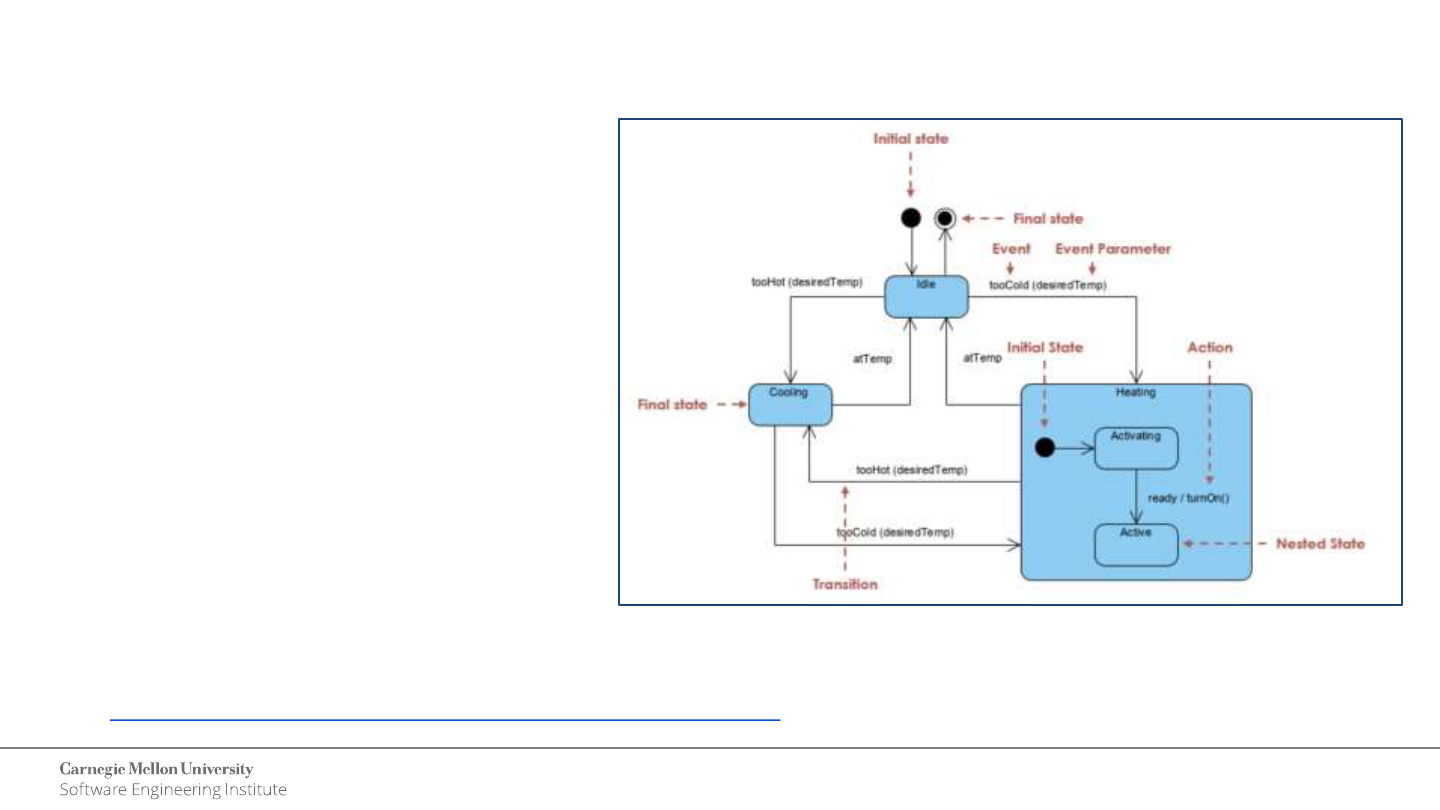
UML State Machine Diagram
Source: https://www.visual-paradigm.com/guide/uml-unified-modeling-language/about-state-diagrams/
A State Machine is a behavior that
specifies the sequences of states an
object goes through during its
lifetime in response to events,
together with its responses to those
events.
State Machine Diagram consists of
states, transitions, events, and
activities. They are especially
important in modeling the behavior
of an interface, class, or
collaboration.

9
Digital Modeling Training
© 2023 Carnegie Mellon University
[DISTRIBUTION STATEMENT A] This material has been approved for public release
and unlimited distribution. Please see Copyright notice for non-US Government use and
distribution.
UML Sequence Diagram
The Sequence diagram is a type of
Interaction diagram that focuses on
the Message interchange between
various Lifelines.
A Sequence diagram shows the
interaction information with an
emphasis on the time sequence.
The diagram has two dimensions: the
vertical axis represents time. And
the horizontal axis represents the
participating objects.
Source: https://docs.nomagic.com/display/MD190/Sequence+diagram, https://www.edrawmax.com/article/sequence-diagram-example.html

10
Digital Modeling Training
© 2023 Carnegie Mellon University
[DISTRIBUTION STATEMENT A] This material has been approved for public release
and unlimited distribution. Please see Copyright notice for non-US Government use and
distribution.
Digital Modeling Training
Section 2: Systems Viewpoint
Overview

11
Digital Modeling Training
© 2023 Carnegie Mellon University
[DISTRIBUTION STATEMENT A] This material has been approved for public release
and unlimited distribution. Please see Copyright notice for non-US Government use and
distribution.
Systems Viewpoint
“The DoDAF-described Models within the Systems Viewpoint describes systems and
interconnections providing for, or supporting, DoD functions.
DoD functions include both warfighting and business functions.
The Systems Models associate systems resources to the operational and capability
requirements.
These systems resources support the operational activities and facilitate the exchange of
information.
The Systems DoDAF-described Models are available for support of legacy systems.
As architectures are updated, they should transition from Systems to Services and utilize the
models within the Services Viewpoint.”
[DoDAF V2.0 Volume II]
Source: https://docs.nomagic.com/display/UPDM2P190SP4/Systems+viewpoint

12
Digital Modeling Training
© 2023 Carnegie Mellon University
[DISTRIBUTION STATEMENT A] This material has been approved for public release
and unlimited distribution. Please see Copyright notice for non-US Government use and
distribution.
Process Guide
13
Digital Modeling Training
© 2023 Carnegie Mellon University
[DISTRIBUTION STATEMENT A] This material has been approved for public release
and unlimited distribution. Please see Copyright notice for non-US Government use and
distribution.
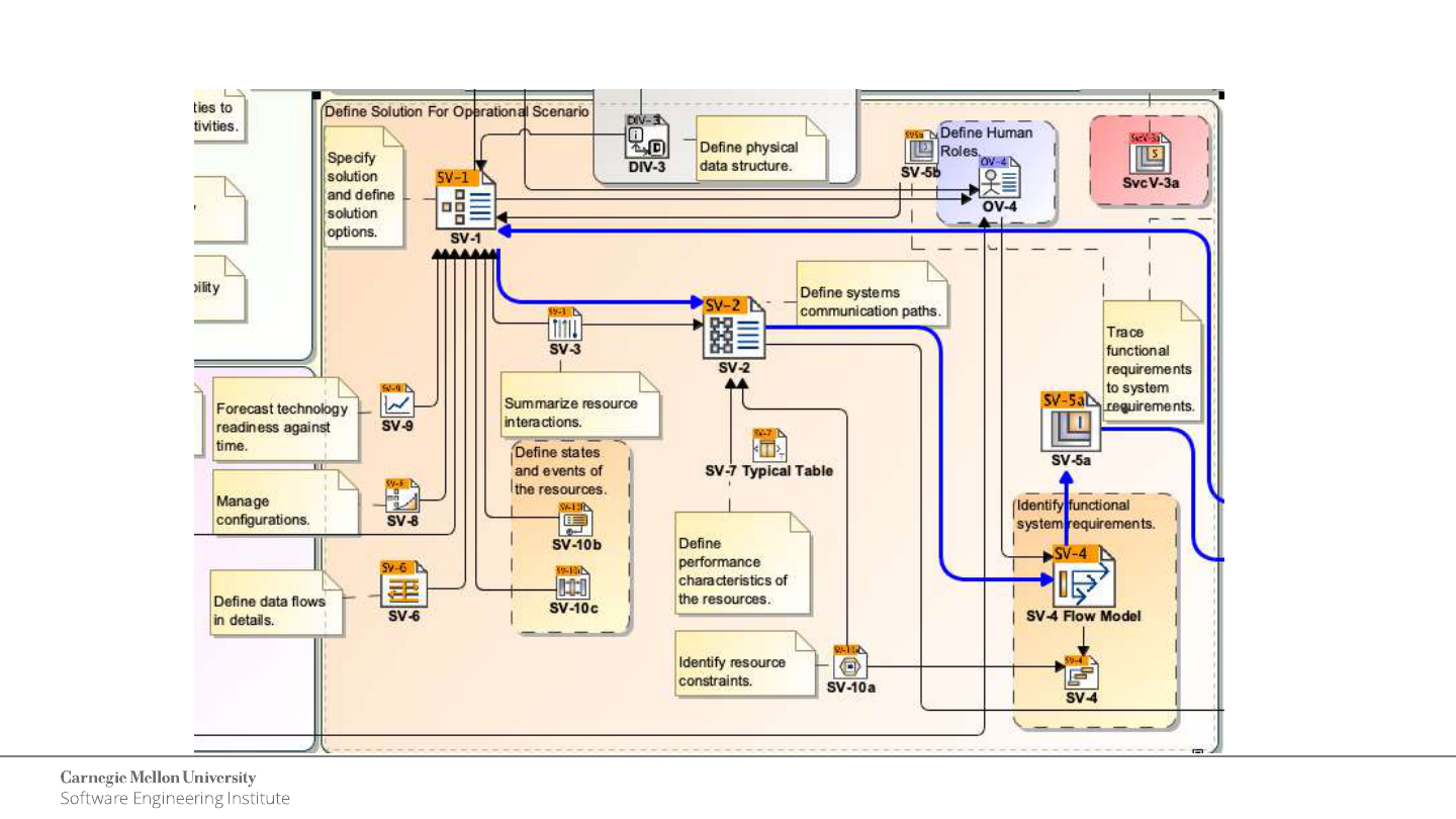
Process Guide – Systems Viewpoint

14
Digital Modeling Training
© 2023 Carnegie Mellon University
[DISTRIBUTION STATEMENT A] This material has been approved for public release
and unlimited distribution. Please see Copyright notice for non-US Government use and
distribution.
DoDAF to SysML Mapping
Source: “Model Based Systems Engineering and Systems Modeling Language”, DoDAFPlenary, January 5,2012

15
Digital Modeling Training
© 2023 Carnegie Mellon University
[DISTRIBUTION STATEMENT A] This material has been approved for public release
and unlimited distribution. Please see Copyright notice for non-US Government use and
distribution.
SV-1 Systems Interface Description
The SV-1 addresses the composition and interaction of Systems.
For DoDAF V2.0, the SV-1 incorporates the human elements as types of Performers - Organizations and
Personnel Types.
The SV-1 links together the operational and systems architecture models by depicting how Resources are
structured and interact to realize the logical architecture specified in an OV-2 Operational Resource Flow
Description.
SV-1 can be represented using:
• SV-1 diagram is based on the UML Class diagram.
• SV-1 diagram is based on the UML Composite Structure diagram.
• UML Class diagram.
• UML Composite Structure Diagram.
• SysML Block Definition Diagram.
• SysML Internal Block diagram.
Source: https://docs.nomagic.com/display/UPDM2P190SP4/SV-1+Systems+Interface+Description

16
Digital Modeling Training
© 2023 Carnegie Mellon University
[DISTRIBUTION STATEMENT A] This material has been approved for public release
and unlimited distribution. Please see Copyright notice for non-US Government use and
distribution.
SV-1 Diagram
Source: https://docs.nomagic.com/display/UPDM2P190SP4/SV-1+Systems+Interface+Description

17
Digital Modeling Training
© 2023 Carnegie Mellon University
[DISTRIBUTION STATEMENT A] This material has been approved for public release
and unlimited distribution. Please see Copyright notice for non-US Government use and
distribution.
SV-2 Systems Resource Flow Description
SV-2 specifies the System Resource Flows between Systems and may also list the
protocol stacks used in connections.
SV-2 DoDAF-described Model is used to give a precise specification of a connection
between Systems. This may be an existing connection or a specification for a connection
that is to be made.
SV-2 can be represented using:
• SV-2 diagram is based on the UML Class diagram.
• SV-2 diagram is based on the UML Composite Structure diagram.
• UML Class Diagram.
• UML Composite Structure Diagram.
• SysML Block Definition Diagram.
• SysML Internal Block Diagram.
Source: https://docs.nomagic.com/display/UPDM2P190SP4/SV-2+Systems+Internal+Resource+Flow+Description

18
Digital Modeling Training
© 2023 Carnegie Mellon University
[DISTRIBUTION STATEMENT A] This material has been approved for public release
and unlimited distribution. Please see Copyright notice for non-US Government use and
distribution.
SV-2 Diagram
Source: https://docs.nomagic.com/display/UPDM2P190SP4/SV-2+Systems+Internal+Resource+Flow+Description

19
Digital Modeling Training
© 2023 Carnegie Mellon University
[DISTRIBUTION STATEMENT A] This material has been approved for public release
and unlimited distribution. Please see Copyright notice for non-US Government use and
distribution.
SV-3 Systems-Systems Matrix
SV-3 enables a quick overview of all the system resource interactions specified in one or
more SV-1 Systems Interface Description models.
Source: https://docs.nomagic.com/display/UPDM2P190SP4/SV-3+Systems-Systems+Matrix

20
Digital Modeling Training
© 2023 Carnegie Mellon University
[DISTRIBUTION STATEMENT A] This material has been approved for public release
and unlimited distribution. Please see Copyright notice for non-US Government use and
distribution.
SV-4 Systems Function Description
The SV-4 addresses human and system functionality.
A SV-4 diagram for System Function hierarchies. This diagram is based on the UML Class
diagram.
Source: https://docs.nomagic.com/display/UPDM2P190SP4/SV-4+Systems+Functionality+Description

21
Digital Modeling Training
© 2023 Carnegie Mellon University
[DISTRIBUTION STATEMENT A] This material has been approved for public release
and unlimited distribution. Please see Copyright notice for non-US Government use and
distribution.
SV-4 Systems Function Flow Description
An SV-4 diagram for System Function flows. This diagram is based on the UML Activity
diagram.
Source: https://docs.nomagic.com/display/UPDM2P190SP4/SV-4+Systems+Functionality+Description

22
Digital Modeling Training
© 2023 Carnegie Mellon University
[DISTRIBUTION STATEMENT A] This material has been approved for public release
and unlimited distribution. Please see Copyright notice for non-US Government use and
distribution.
SV-10b Systems State Transition Description
The SV-10b is a graphical method of describing a
resource (or system function) response to various
events by changing its state.
The diagram basically represents the sets of
events to which the resources in the Activities
respond (by taking an action to move to a new
state) as a function of its current state.
Each transition specifies an event and an action.
SV-10b can be represented using a UML State
Machine diagram.
Source: https://docs.nomagic.com/display/UPDM2P190SP4/SV-10b+Systems+State+Transition+Description

23
Digital Modeling Training
© 2023 Carnegie Mellon University
[DISTRIBUTION STATEMENT A] This material has been approved for public release
and unlimited distribution. Please see Copyright notice for non-US Government use and
distribution.
SV-10c Systems Event-Based Description
The SV-10c provides a time-
ordered examination of the
interactions between functional
resources.
Each event-trace diagram should
have an accompanying
description that defines the
particular scenario or situation.
SV-10c can be represented using a
UML Sequence Diagram.
Source: https://docs.nomagic.com/display/UPDM2P190SP4/SV-10c+Systems+Event-Trace+Description

24
Digital Modeling Training
© 2023 Carnegie Mellon University
[DISTRIBUTION STATEMENT A] This material has been approved for public release
and unlimited distribution. Please see Copyright notice for non-US Government use and
distribution.
Requirements Traceability

25
Digital Modeling Training
© 2023 Carnegie Mellon University
[DISTRIBUTION STATEMENT A] This material has been approved for public release
and unlimited distribution. Please see Copyright notice for non-US Government use and
distribution.
Block Interactions

26
Digital Modeling Training
© 2023 Carnegie Mellon University
[DISTRIBUTION STATEMENT A] This material has been approved for public release
and unlimited distribution. Please see Copyright notice for non-US Government use and
distribution.
Behavior Allocation

27
Digital Modeling Training
© 2023 Carnegie Mellon University
[DISTRIBUTION STATEMENT A] This material has been approved for public release
and unlimited distribution. Please see Copyright notice for non-US Government use and
distribution.
Digital Modeling Training
Section 3: Demo in the model

28
Digital Modeling Training
© 2023 Carnegie Mellon University
[DISTRIBUTION STATEMENT A] This material has been approved for public release
and unlimited distribution. Please see Copyright notice for non-US Government use and
distribution.
