
Turbo 310R
X-Plane user guide

This software is an artistic representation
of the subject matter.
Any similarities to any commercial product, equipment, ve-
hicle, device or other, present within this artistic represen-
tation does not constitute or imply an endorsement (by, or
of) the manufacturer(s) and/or trademark holder(s) of that
which may be deemed similar.
This software, including any and all components and con-
tent, © 2018 Military Visualizations Inc. All Rights Reserved.
No replication, reduction, reverse engineering or unauthor-
ized addition to the software, either in whole or in part, is
permitted in any form without the express written permis-
sion of Military Visualizations Inc.
By installing this software, you are hereby agreeing to the
above terms and conditions. Any breach of the above EULA
will result in litigation, removal of license and/or forfeiture of
continued support.
Any inquiries regarding academic or other professional use
of this software should be directed via e-mail to info@milviz.
com.

Turbo 310R User Guide
Main Index
Introduction 1
Product Features 2
System Requirements 3
Installation Instructions 4
Uninstalling 7
Updating 7
Product Support 7
Turbocharging the 310R 8
Using the T310R Aircraft Menu 10
Rain Eects for Windows 11
Managing the Fuel System 12
Managing the Electrical System 13
Tutorial: Starting the Turbo 310R 14
Aircraft Specications 20
Recommended Settings & Speeds 20
Aircraft Limitations 21
Credits 22

Turbo 310R User Guide
Welcome!
This User Guide has been prepared to help you
get started with your new Turbo 310R for X-Plane.
It contains useful information about your Turbo
310R’s equipment, operating procedures, and
performance. It also contains instructions for in-
stallation and updating. We recommend that you
take some time to read through this guide from
cover to cover, and to refer to it as needed.
Our interest in your simulation activity has not
ceased with your purchase of the MilViz Turbo
310R. Worldwide, the Military Visualizations sta
stands ready to assist and serve. For technical
support, please post a request on our Turbo 310R
X-Plane support forum. Our dedicated and tal-
ented sta is ready to help you.
For forum access please email oisin@milviz.com
with your proof of purchase and your preferred or
existing forum username.
Bringing the 310R to X-Plane
This isn’t the rst version of the 310R to wear the
MilViz label. The original version of the MilViz 310R
was released way back in 2010 in Microsoft Flight
Simulator X, well known not only for it’s accurate
portrayal of the iconic twin but also for the care-
fully tuned and realistic ight model.
In the spring of 2018 we released the 310R Redux,
for FSX and Prepar3d. This version was a com-
plete overhaul of the original, with enhanced and
updated systems programming, an updated vir-
tual cockpit, new external textures, and a brand
new soundset. In other words, pretty much ev-
erything required in order to bring this aircraft up
to current standards.
In bringing the 310R into the X-Plane world, we’ve
retained the same excellent standards that we’re
know for, while taking advantage of all of the
modern technology available to us in X-Plane 11.
We’re happy to be here, and we’re very happy that
you could join us. Thanks and enjoy the ride!
Page 1

Turbo 310R User Guide
Product Features
> Designed for X-Plane 11
» Optimized for X-Plane 11 engine and handling behavior
» Inclusion of PBR materials and textures
» Advanced FMOD sounds inside and out
> High Quality Textures & Modeling
» Physical Based Rendering (PBR) materials and textures for superb
real-time reections and shine
» Exterior and interior rendered with exacting detail and precision
» High resolution, beautiful textures with realistic weathering eects
» Smoothly animated parts inside and out
> Realistic Simulation of the Turbo 310R
» Behavior designed to closely simulate the real world
» Authentic turbo performance and handling
» Realistic fuel load and tank capacities
» Realistic weight & balance
> Advanced Autopilot System
» Autopilot mimics real world behavior, requiring hands-on operation
» Simulation of VOR station ‘Cone of Confusion’ when approaching
VOR station, requiring monitoring and switching from NAV to HDG
to maintain proper course
» Authentic servo behavior reecting realistic speed and accuracy
> GPS Conguration Options
» FPS friendly X-Plane GNS 530 & GNS 430 included by default
» Includes support for RealityXP’s GTN 750* & 650* integrated into
the 3D cockpit
> Custom Aircraft Panel
» In-game menu panel allows for display of ground elements,
switching liveries and changing the GPS displays
* RealityXP products not included; may not be available for all operating systems
Page 2

Turbo 310R User Guide
X-Plane 11
All operating systems which are supported by the
X-Plane 11 platform. At the time of publication, this
includes:
• OS X: OS X 10.10 or newer
• Windows: Windows 7, 8, or 10, 64-bit
• Linux (While any distribution which successfully
runs X-Plane 11 should be capable of operating this
aircraft, distribution specic issues with X-Plane
11 that may causes issues with this aircraft are not
supported.)
Intel Core i3, i5, or i7 CPU with 2 or more cores,
or AMD equivalent. (Recommended: Intel Core
i5 6600K at 3.5 ghz or faster.)
DirectX 11-capable video card from NVIDIA, AMD or In-
tel with at least 1 GB VRAM. (Recommended: DirectX
12-capable video card from NVIDIA, AMD or Intel with
at least 4 GB VRAM, GeForce GTX 1070 or better or
similar from AMD.)
8 GB RAM (Recommended: 16-24 GB RAM or more.)
1.5 GB or greater free hard drive space.
Joystick, yoke, or other gaming controller (a means of
controlling the aircraft rudder, either with twist joy-
stick function or dedicated pedals, is additionally rec-
ommended).
Please note that an active internet connection is re-
quired for successful activation of this product.
System Requirements
The following requirements apply as a
minimum to successfully install, con-
gure and operate the MilViz Turbo
310R for X-Plane.
(Please note that these requirements
represent the minimum required; your
choice of scenery, location, and simu-
lator settings may place additional
demands on your simulation platform
that may ultimately aect your simu-
lation experience.)
Supported Platforms:
Supported Operating Systems:
Processor (CPU):
Video Card (GPU):
System Memory (RAM):
Hard Drive:
Gaming Controller:
Internet Connection:
Page 3

Turbo 310R User Guide
Beginning Installation
After purchase, you will have been given a link
or an option to download a compressed le. This
compressed le contains all of the folders and
les for the MilViz Turbo 310R for X-Plane.
Using a le compression utility of your choice, de-
compress this le to a location or folder of your
choosing.
2
Identifying Files to Copy
Within this newly decompressed folder, you will
nd a sub-folder containing both les and fold-
ers.
You’ll know that you have identied the correct
folder when the contents resemble the below im-
age.
This folder containing the below les is the air-
craft folder that needs to be placed within the X-
Plane le structure.
Creating a Destination Folder
In the X-Plane 11 le structure, all aircraft are
placed within the ‘X-Plane 11\Aircraft’ folder, gen-
erally in developer specic folders. This structure
helps to organize your aircraft collection.
While it is largely up to the end user on how they
wish to organize their aircraft, we recommend
creating a sub-folder within the ‘X-Plane 11\Air-
craft’ folder titled ‘MilViz’.
Installation Instructions
1 3
Page 4

Turbo 310R User Guide
Copying the Aircraft
You should now have a folder structure that re-
sembles the following:
‘X-Plane 11\Aircraft\MilViz’
Copy the aircraft folder you identied in Step 2
into this newly created MilViz folder. Done cor-
rectly, it should closely resemble the following
image.
Verify Installation
Once the aircraft folder is installed correctly,
launch X-Plane 11.
On the left side of the Flight Conguration UI
screen, you should be able to nd your new Turbo
310R.
You may now select it and start a ight (making
any other desired adjustments to starting loca-
tion & weather, of course).
Enter Serial Number
Note: Please ensure that your computer is
connected to the internet before continuing.
At time of purchase, you should also have been
given a serial number for your aircraft. This se-
rial number is used to register your aircraft, and is
tied to your individual purchase.
On the rst launch of the aircraft, a window will
automatically show, asking for the serial number.
Enter the number you received and press the ‘Ac-
tivate’ button to continue.
Installation Instructions (continued)
4 5 6
Page 5

Turbo 310R User Guide
Verify Activation
After clicking on the ‘Activate’ button, a dialog
should display in green text which conrms the
successful activation of the aircraft.
It also prompts you to reload the aircraft to com-
plete the activation process.
Reload Aircraft
To reload the aircraft, go to the Developers tab
in the upper system menu, and from there, scroll
down to ‘Reload the Current Aircraft’. Click on this
choice.
You may note that the simulator may seem to
momentarily freeze, this is normal behavior while
the simulator reloads the aircraft.
Go Fly!
Once your aircraft has successfully reloaded, the
installation and activation process is complete.
Enjoy your ights!
Installation Instructions (continued)
7 8 9
Page 6

Turbo 310R User Guide
In the event that you are notied of an update to
the MilViz Turbo 310R, it is highly recommended
that you completely uninstall the previous ver-
sion before you install the newly updated version.
This will ensure that the correct versions of any
changed les are present.
The MilViz Turbo 310R may be un-installed very
simply by deleting the aircraft folder that you
manually copied into the X-Plane 11 le structure.
Note: Prior to uninstalling the aircraft, please be
sure to back up any customized les or custom
liveries you have installed if you wish to keep
them.
UpdatingUninstalling Product Support
We are deeply committed to the satisfaction of
our customers. If you encounter any issues with
your product or require assistance, or just have a
general question, we encourage you to visit our
forums at http://milviz.com/forum/.
Support forums for our individual products are
restricted to owners of that product. To regis-
ter for a specic support forum, please contact
[email protected] for registration information and
details. Please note that proof of purchase will be
required.
Page 7

Turbo 310R User Guide
Turbocharging the 310R
One of the primary dierences between this air-
craft and the version that we have previously
published (for Flight Simulator X and Prepar3D)
is a bit of a big one: as the name implies, the Tu r-
bo 310R is equipped with turbocharged engines.
Both engines are equipped with a turbocharger
and related components; this allows the aircraft
to maintain rated power to 16,000 feet. The en-
gines behave like normally aspirated engines
would, with some diering engine characteris-
tics. As such, it’s worthwhile to explain some of
the things aected by turbocharging, as well as
note some of the correct procedures to be fol-
lowed.
Referring to the diagram on this page, it’s use-
ful to follow the path of induction air through the
engine up to being expelled as exhaust gases.
First, engine induction air is taken in through
the Ram Air Inlet (1), passing through a lter into
the Compressor (2), where the air is then com-
pressed. This compressed, pressurized air then
passes into the engine cylinders via the Induc-
tion Manifold (3) where, mixed with fuel, it is
burned, exiting the engine cylinders via the Ex-
haust Manifold (4). The exhaust gases provide
driving power for the Turbine (5) which in turn
drives the Compressor.
The power created by the turbine would allow
the engine to exceed the maximum 32.0 inches
Hg. manifold pressure, so therefore a Waste Gate
(6) is used so that excess exhaust gases can be
expelled prior to passing through the turbine.
In studying this path of induction air through the
engine, it makes sense that anything which af-
fects the ow of induction air into the compres-
sor, or exhaust gases into the turbine, will also af-
fect the speed of the turbocharger system.
Now, any change in the ow of induction air will
have no eect if the waste gate is open, because
Page 8
(1)Ram aiR inlet
induction aiR FilteR
(2)compRessoR
(5)tuRbine
main
exhaust
(6)Waste
Gate
thRottle
ValVe
(3)induction
maniFold
(4)exhaust
maniFold
ambient enGine
induction aiR
pRessuRized enGine
induction aiR
enGine exhaust aiR
mechanical actuation
Turbo Systems Diagram
for the Turbo 310R
the waste gate automatically serves to hold the
compressor discharge pressure constant. This
occurs below 16,000 feet with full throttle and
RPM. Above 16,000 feet, the waste gate is op-
erated by the turbo system to limit the manifold
pressure appropriately, at approximately 2.2
times the ambient air pressure.

Turbo 310R User Guide
This automatic control of the waste gate by the turbo system will provide,
approximately, the placarded manifold pressure during single engine climb,
however all engine climbs at higher speeds or with closed cowl aps may re-
quire some adjustments to the throttle to maintain the proper manifold pres-
sure.
When the waste gate is fully closed, any change in turbocharger speed will
equal a change in engine operation. Anything that results in an increase or
decrease of turbine speed will cause an increase or decrease in manifold
pressure.
Manifold Pressure Variation vs. Altitude
As noted previously, at full throttle the turbocharger is capable of maintaining
the maximum allowable 32.0 inches Hg. manifold pressure up to 16,000 feet.
The RPM range for maintaining the maximum allowable manifold pressure is
2500 - 2700 RPM; if a lower RPM range is selected for a cruise climb such as
2300 - 2400 RPM, the manifold pressure may start to drop before 16,000 feet.
The turbo system controller does not include a pressure compensated waste
gate and therefore only operates automatically at full throttle. If a lower mani-
fold pressure is selected by the pilot, the throttle will require manual advances
to maintain the selected manifold pressure as the aircraft climbs.
Manifold Pressure Variation vs. Airspeed
When the aircraft is operated at full throttle at altitudes below 16,000 feet,
the waste gate is open, therefore changes in airspeed have little eect on the
manifold pressure.
At high altitudes, once the waste gate is closed, dierences in airspeed will
have a small, but noticeable, eect on manifold pressure.
Fuel Flow Variations vs. Manifold Pressure
This is one area where we are forced to deviate from real world behavior due
to a limitation within the X-Plane platform. Proper behavior is that fuel pump
output and fuel ow is regulated by engine speed and compressor discharge
pressure. The practical (real world) end result is that fuel ow adjustments by
the pilot are minimized greatly, reduced to small initial adjustments on takeo
or climb-out for the proper rich setting, lean-out in cruise, and return to full
rich for approach and landing.
However, X-Plane does not model this behavior correctly, instead choosing to
model ambient pressure only; this causes the turbocharged engine to behave
as a normally aspirated engine would in regards to fuel ow.
As such, as the aircraft climbs, the fuel levers will need to be managed by the
pilot in order to lean the fuel mixture so as to allow the engines to achieve
rated power and proper climb rates.
So - during the climb it is advised that the pilot should strive to maintain an
EGT of 1050° F by progressively leaning the fuel mixture, before leaning for
cruise power once at altitude.
Momentary Overboost Of Manifold Pressure
Under certain circumstances, such as rapid throttle movement, it is possi-
ble that the engine can be overboosted above the maximum allowable 32.0
inches Hg. manifold pressure. This could occur during the takeo roll or dur-
ing a change in full throttle operation while in ight. Slight, but momentary,
overboosting is not considered detrimental to the engine, but can usually be
controlled by slower throttle movements.
Altitude Operation
A turbocharged aircraft is capable of climbing faster and higher than a nor-
mally aspirated aircraft can, as such, the pilot should be aware of the possibil-
ity of fuel vaporization being encountered.
It is recommended that the auxiliary fuel boost pump switches be turned ON
when climbing to altitudes above 12,000 feet. In addition, the fuel pumps
should be left ON for several minutes after cruise in level ight has been es-
tablished.
Page 9

Turbo 310R User Guide
Using the T310R Aircraft Menu
The MilViz Turbo 310R includes a custom aircraft
menu panel which is accessible once the aircraft
is loaded. From this menu, it’s possible to perform
the following actions:
> Remove / Attach external features
> Change Aircraft Liveries
> Switch between GPS options
The menu panel may be opened (or closed) by uti-
lizing the X-Plane Menu Bar located at the top of
the screen, and choosing “Plugins > MilViz T310R
> Show/Hide Options”.
Clicking on the images of the chocks or the ‘Re-
move Before Flight’ ag allows you to hide or
show those respective features on the aircraft.
The next section allows you to switch aircraft liv-
eries on the y by clicking the arrows to the left or
right of the aircraft image.
The GPS options allow you to switch between the
stock X-Plane GNS 530/430 and the RealityXP
GTN 750/650 variants (not included).
To switch, click the image shown for either Nav
1 or Nav 2. The changes will immediately be re-
ected in the aircraft.
IMPORTANT: When transitioning between the
Reality XP GTN 750 and the stock X-Plane GNS
530, be sure to turn the GTN 750 OFF in the pl-
ugins menu. This is found at ‘Plugins>Reality XP
GTN> GTN1’.
Page 10

Turbo 310R User Guide
Rain Eects for Windows
The MilViz Turbo 310R includes a plugin which
adds rain eects to all windows.
Rain will accumulate when the aircraft is parked,
will be aected by wind while moving or ying,
and will realistically aect the appearance of
anything viewed through the windows.
These eects add an improved sense of realism
Page 11
and immersion while ying through inclement
weather; instead of seeing rain falling around
you, rain is now something directly aecting the
aircraft itself.
The plugin which adds these eects is compat-
ible with Windows and Mac. If using Linux, the
aircraft will still work, but the rain eects will be
missing.
This plugin requires the latest VCC distributable
from Microsoft. If it is not installed on your sys-
tem, it can be found at: https://support.micro-
soft.com/en-us/help/2977003/the-latest-sup-
ported-visual-c-downloads

Turbo 310R User Guide
Managing the Fuel System
The fuel system in the MilViz Turbo 310R is intended to provide a very high
delity experience and closely replicates actual use.
The T310R is equipped with two main fuel tanks, often referred to as ‘wingtip’
or ‘tip’ tanks. Each tank has a usable capacity of 50 gallons. In addition, there
are also two auxiliary fuel tanks, each with a usable capacity of 31.5 gallons.
The total amount of usable fuel available to the pilot is 163 gallons.
Each engine is typically fed by the tank on that respective side, but the air-
plane also features the capability to crossfeed the fuel from the main tank on
the opposite side from the engine. Note that it is not possible to crossfeed fuel
from the auxiliary fuel tanks.
Fuel Controls
The MilViz T310R features a pair of fuel switches and placards located im-
mediately aft of the pedestal, between the front seats. The left fuel switch
controls the fuel ow for the left engine, and the right fuel switch controls the
fuel for the right engine.
The handles of the switches are rotated by the pilot in order to select a desired
position as outlined on the placard below the switch and indicated by the ta-
pered end of the switch handle. In the MilViz T310R for X-Plane, the desired
tank can be switched to by clicking on the placard area with the LEFT MOUSE
BUTTON.
Fuel Gauge
The fuel gauge featured on the T310R is a dual needle type, with the left nee-
dle corresponding to the left tanks and the right needle corresponding to the
right tanks. The gauge is graduated in gallons of fuel remaining on the blue
arc, and pounds of fuel remaining on the white arc.
The fuel gauge automatically shows the usable fuel remaining on the tank
selected by the fuel control for that engine. If the main fuel tank is selected by
the fuel control switch, the gauge will display the remaining usable fuel for the
main fuel tank. If the auxiliary fuel tank is selected by the fuel control switch,
the gauge will display the remaining usable fuel for the auxiliary tank.
The switch immediately below the fuel
gauge is a three position momentary
switch that is spring loaded to the
center position.
To temporarily display the fuel quan-
tity remaining in the main tanks, move
the mouse over the upper portion of
the switch (an up arrow will display)
then click and hold the switch with the
LEFT MOUSE BUTTON. To temporarily
display the fuel quantity in the auxil-
iary tanks, repeat the process, except
over the lower portion of the switch (a
down arrow will display).
The indicator lamps to either side of
the switch will illuminate when the pi-
lot has selected the auxiliary fuel tank
for the associated engine. Warning
lamps on the center area of the panel
will illuminate to notify the pilot of low
fuel quantity in the selected tank.
All lamps are of the push-to-test type.
Page 12

Turbo 310R User Guide
Managing the Electrical System
The electrical system in the Turbo 310R is designed to respond in a believable
manner in comparison with the real aircraft. There are a few exceptions in that
the circuit breakers, although modeled, are not operable, nor are the emer-
gency alternator eld switches and the emergency avionics power switch
(these being located on the lower right side of the circuit breaker panel).
Electrical power in the T310R is supplied by a 28-volt, negative-ground, direct
current system powered by alternators on each engine. A 24-volt battery is
located in the left wing outboard of the engine nacelle.
Warning of low system voltage is provided by warning lamps on the instrument
panel, next to the voltammeter. The lamps will illuminate when the bus volt-
age decreases below 25 volts (approximately). These lights can sometimes
illuminate when the engine is idling at an RPM insucient to provide optimal
alternator power output. The lamps are push-to-test, and can be tested by
clicking them with the LEFT MOUSE BUTTON.
Independent alternator switches and a separate master battery switch is pro-
vided as a means of checking for a malfunctioning alternator circuit and to
permit that circuit to be turned o. When an engine is not running, the switch
for that alternator should be turned OFF.
The master battery switch and the alternator switches are toggled upwards
(ON) and downwards (OFF) by clicking the switch with the LEFT MOUSE BUT-
TON.
Amperage / Voltage Indicator
A voltammeter is located on the instrument panel directly above the pedestal,
located between landing gear controls and the wing aps switch. This gauge
provides for monitoring of alternator current output, battery charge or dis-
charge rate and aircraft bus voltage.
An AMP METER SELECT switch, located to the left of the voltammeter indica-
tor, has labelled indications for L ALT, R ALT, BAT, and VOLT. By positioning this
switch to L ALT, R ALT or BAT position, the respective alternator or battery am-
perage can be monitored. By positioning the switch to the VOLT position, the
electrical system bus voltage can be monitored.
To position the switch, move the mouse over the rotary switch. Movement
to one side or the other will cause a clockwise or counter-clockwise arrow to
display; click the LEFT MOUSE BUTTON to rotate the switch in the respective
direction.
When measuring the amperage draw for the alternators or the battery, refer-
ence the top white section of the gauge. When measuring the voltage draw,
reference the bottom blue section of the gauge.
In addition to the voltammeter and the amp meter select switch, the warning
lights for low system voltage are positioned in this location.
Page 13

Turbo 310R User Guide
Tutorial: Starting the Turbo 310R
For this portion of the T310R user guide, we’ll
present a step-by-step walkthrough of how to
take the Turbo 310R from a cold and dark state
all the way up to being ready for taxi and takeo.
The T310R cabin is an easy place in which to nd
your way around. For a twin, the controls are well
laid out and not overly complex. This makes the
T310R an ideal airplane both for those who desire
a relaxing ight in an elegant aircraft, or for those
learning the ins and outs of ying a twin.
The instrumentation installed in the MilViz T310R
panel is quite standard and should be familiar to
the majority of simulation pilots.
Equipped with dual yokes, the T310R can be own
from either the pilot’s or the copilot’s position.
However, the left hand yoke does feature addi-
tional controls for the autopilot which the right
hand yoke does not have. In addition, the majori-
ty of the traditional ight instruments are located
on the left hand panel in front of the pilot, where
as the right hand panel is composed primarily of
the engine instrumentation.
Although the engines and the underlying sys-
tems in the T310R are realistic in nature, there is
no wear n’ tear simulation included, nor are there
any custom failures beyond what is a default part
of the X-Plane platform.
Aside from the specications and limitations
we’ve listed elsewhere within this user guide, our
primary advice is simply to pay attention to the
limitations indicated on the instrumentation, pri-
marily the airspeed indicator, the manifold pres-
sure gauge and the RPM gauge.
Have fun and keep the blue side up!
Page 14

Turbo 310R User Guide
Preight Actions
1) Adjust fuel quantities and weight as desired for ight
> Adjustments are made through the Flight Conguration UI
a) When selecting the aircraft, press the “Customize” button
b) Next, press the “Weight, Balance & Fuel” button
c) Adjust as desired
> Tanks 1 & 2 (the main tip tanks) are lled before aux tanks
> The usable C.G. range is from -1.5” (forward) to +2.8” (aft)
1-B
1-A
1-C
2) Remove wheel chocks and covers
> This action can be done through a custom menu panel
> This panel is opened through the top UI menu bar
> Choose “Plugins > MilViz T310R > Show/Hide Options”
2
Page 15

Turbo 310R User Guide
Before Starting Engines
1) Set Parking Brake
> Hold the left mouse button, pull the lever out to set
2) Switch Fuel Selectors to Main Tanks
> Left click on the desired placard area to turn the selectors
3) Set Throttle, Propeller & Mixture levers
a) Set Mixture levers fully rich (forward)
b) Set Propeller levers fully forward
c) Set Throttle levers open approximately one inch
4) Turn on Battery and Alternator Switches
> The lower switch panel is located directly below the yoke
> For easier access, the yoke may be hidden from view
> To hide the yoke, left click on the yoke shaft
1
2
43
Page 16

Turbo 310R User Guide
Before Starting Engines (continued)
5) Set lighting switches and dials as required
> Toggle switches ON/OFF with the left mouse button
> Rotate dials to adjust brightness with the mouse wheel
6) Set Altimeter to correct barometric pressure or elevation
> Use the adjustment knob at the bottom left of the altimeter
> Rotate the mouse wheel when over the adjustment knob
7) Open left and right Cowl Flaps
> Hold the left mouse button, pull or push control handles
5
6
7
Page 17
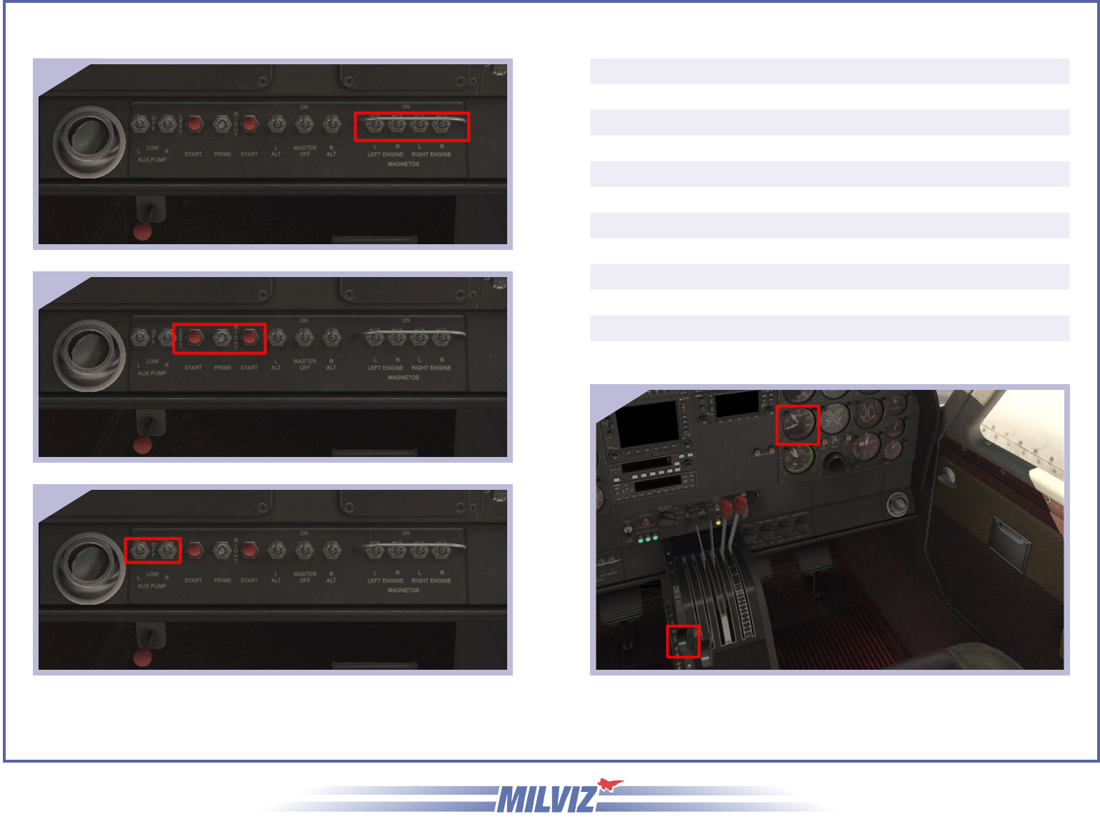
Turbo 310R User Guide
Starting Engines
(left engine is started rst, then right engine)
1) Turn on Magneto Switches
> Toggle switches ON with the left mouse button
2) Start Engine
a) Press Start button for desired engine
> Click the button using the left mouse button
b) Engage the Primer left or right, depending on engine
> Click and hold the primer switch and drag to left or right
3) Turn Auxiliary Fuel Pump switch to LOW
> Toggle switch to LOW with the left mouse button
4) Set Throttle lever to obtain 800 to 1000 RPM
(repeat steps 1 through 4 for right engine)
1
2
3
4
Page 18

Turbo 310R User Guide
Before Taxi
1) Turn on Avionics Master Switch
> Toggle switch ON with the left mouse button
2) Turn on and set Avionics as desired
3) Release Parking Brake
> Brakes will release by pressing the toe brakes
> Brakes may also be released by using the control handle
1
2
3
You’re cleared for takeo, enjoy your ight!
Page 19

Turbo 310R User Guide
Aircraft Specications
Number of Engines 2
Engine Model Number: TSIO-520-BB
Engine Type: Turbocharged, fuel injected, di-
rect drive, air-cooled, horizontally
opposed, six cylinder, 520 cubic-
inch displacement.
Horsepower: 285 rated horsepower at 2700
RPM and 32.0 inches Hg. mani-
fold pressure to the critical alti-
tude of 16,000 feet.
Propellers: 2, 3-blade, 6’ 6” diameter, con-
stant speed, full feathering, non-
reversible hydraulically actuated.
Maximum Takeo Weight: 5500 lbs
Maximum Landing Weight: 5400 lbs
Maximum Zero Fuel Weight: 5015 lbs
Standard Empty Weight: 3467 lbs
Maximum Useful Load: 2068 lbs
Main Fuel Tanks - Usable 100 U.S. Gallons (total)
Auxiliary Fuel Tanks - Usable 63 U.S. Gallons (total)
Total Wing Area: 179 square feet
Wing Loading: 30.73 lbs per square foot
Power Loading: 9.65 lbs per horsepower
Normal Takeo: 2700 RPM, Full Throttle, Flaps 0° Raise nosewheel at 80 KIAS, Lift-o at 92 KIAS (5500 lbs Max Weight)
Max Performance Takeo: 2700 RPM, Full Throttle, Flaps 15° Raise nosewheel at 70 KIAS, Lift-o at 82 KIAS (5500 lbs Max Weight)
Best Angle-of-Climb Speed (S.L.): 81 KIAS (at 5500 lbs Max Weight)
Best Rate-of-Climb Speed (S.L.): 105 KIAS (at 5500 lbs Max Weight)
Cruise Climb: 2350 RPM, 29 In. Hg. 115 to 140 KIAS
Maximum Climb: 2700 RPM, Full Throttle below
16,000 feet, Max allowable M.P.
above 16,000 feet.
105 KIAS
Cruise: 2100 to 2350 RPM and 15.0 to 29.0
In. Hg. or 2200 to 2300 RPM and
15.0 to 30.0 In. Hg.
Minimum Multi-Engine Approach
Speed:
93 KIAS (at 5400 lbs Max Weight)
Recommended Settings & Speeds
Page 20

Turbo 310R User Guide
Aircraft Limitations
Engine Limitations
Altitude (Feet) Allowable
Manifold
Pressure
(In. Hg.)
Engine
RPM
Brake
Horse-
power
S.L. to 16,000 feet 32.0 2700 285
18,000 30.7 2700 268
20,000 29.0 2700 246
22,000 26.4 2700 222
24,000 24.3 2700 198
26,000 22.2 2700 176
28,000 20.2 2700 155
30,000 18.5 2700 136
32,000 17.0 2700 117
Operational Limitations
Maneuvering Speed VA (knots) 148 KIAS Do not make abrupt or sudden control movements above this speed.
Maximum Flap Extended Speed VFE (Knots) 15° 158 KIAS Do not exceed this speed at this ap setting.
Maximum Flap Extended Speed VFE (Knots) 35° 139 KIAS Do not exceed this speed at this ap setting.
Maximum Gear Operating Speed VLO (Knots) 138 KIAS Do not operate the landing gear above this speed.
Maximum Gear Extended Speed VLE (Knots) 138 KIAS Do not extend the landing gear above this speed.
Minimum Controllable Airspeed VMCA (Knots) 80 KIAS This is the minimum speed at which the aircraft is controllable with one engine
inoperative and a 5° bank towards the operative engine
One Engine Inoperative Best Rate-of-Climb Speed Vy
(Knots)
106 KIAS The speed delivering the greatest gain in altitude in the shortest time with one
engine inoperative at sea level, standard day conditions and level ight
Never Exceed Speed VNE (Knots) 223 KIAS Do not exceed this speed in any type of operation
Maximum Cruising Speed VNO (Knots) 181 KIAS Do not exceed this speed except in smooth air and with caution
Page 21

MilViz CT310R (XP) Team
Alan Shafto
Armando Alva
Daniela Rodriguez Careri
Colin Pearson
Oisin Little
Jim Stewart
Modeling & Textures
3DReach
Testers
OzWookiee
Clinton M. Smith
Stephen Power
RonB
Mike Cameron
Sergio “Raptor” Sanchez
BagoBonez
Monica L. Duerr
John F. Wharton Jr.
Ryan Butterworth
Steve “ Slayer” McNitt
Rain Eects
Saso Kiselkov Rain Eects
by Cooper LeComp (AFM Simulation)
Credits
