
for the PROMATIC-100
™
Key Machine
USER’S MANUAL
Exclusively
Offering
Three
Cutting
Modes
• Manual
• Semi-
Automatic
• Automatic
800-896-7890

2
Hy-Ko Products Company
330•467•7446 800•896•7890 Fax: 330•467•7442 E-Mail: [email protected] www.hykokeys.com
Important Information for Future Reference
Thank you for your recent purchase of our quality-made PROMATIC-100
™
Key Machine.
Please complete the following information log for reference if customer support is needed:
Hy-Ko
®
PROMATIC-100
™
Key Machine
Serial Number:
(Located on the left side of the machine)
Date Put into Service
If you would like to order a Hy-Ko Key Replacement Catalog, please contact Customer Support Services
(See information below).
Phone: 1-800-896-7890
8am – 6pm EST, Monday thru Friday
Fax: 330-467-7442
(24 hours a day, seven days a week)
E-Mail: [email protected]
Mailing Address: Hy-Ko Products Company
60 Meadow Lane
Northfield, OH 44067-1415
Customer Support Services
For Customer and/or Technical Support, please contact us by:
Read this manual first.
© 2010 Hy-Ko Products Company. All rights reserved.

3
Hy-Ko Products Company 330•467•7446 800•896•7890 Fax: 330•467•7442 E-Mail: [email protected] www.hykokeys.com
Important Safety Information 4
Promatic-100 Packaging 5
Portable Shop Vacuum Option 6
How to Connect a Portable Shop Vacuum
Testing After Delivery 7
Duplicating Keys 7-15
The Basic Parts of a Key
Jaw Clamping Guide
Selecting the Correct Jaw Setting
Aligning Key in the Jaws
Shoulder Gauging
Tip Gauging
Three Operating Modes for Cutting Keys 16-21
Manual Operation
Semi-Automatic Operation
Automatic Operation
Deburring Newly Cut Keys
Operating Do’s and Don’ts
Maintenance Tips for More Accurate Duplication
How to Replace the Cutter 22-25
Calibration 26-32
Carriage Stop Calibration
How to Determine the Need for a Carriage Stop Adjustment
Carriage Stop Adjustment Instructions
Spacing Calibration
How to Determine the Need for a Spacing Adjustment
Spacing Adjustment Instructions
Depth Calibration
How to Determine the Need for a Depth Adjustment
Depth Adjustment Instructions
How to Replace the Deburring Brush 33
Troubleshooting Guide 35-42
Warranty 43
All trademarks and tradenames are the property of their respective owners.
Table of Contents

4
Hy-Ko Products Company 330•467•7446 800•896•7890 Fax: 330•467•7442 E-Mail: [email protected] www.hykokeys.com
Important Safety Information
SAFETY DO’s:
• DO wear the safety glasses supplied with the key
machine or other safety glasses when operating the
key cutting equipment.
• DO make sure the machine is off when inserting
or removing keys.
• DO wear clothing that protects against potential
flying metal chips during key cutting or key
deburring. The chips can cause injuries.
• DO ensure that customers or fellow employees are
clear of the machine during operation or key
deburring. Potential flying metal chips can
cause injuries.
• DO ensure that personal grooming and work
clothing contribute to safe operation of the
key machine.
• DO check local and state ordinances regarding age
restrictions on operating certain types of equip-
ment, which may include electrically powered key
cutting machines.
• DO pull back long hair.
SAFETY DON’Ts:
• DO NOT modify or remove any of the safety devices
on the key cutting machine.
• DO NOT touch moving parts during key machine
operation other than those so designated in this
manual.
• DO NOT use the key machine for any other pur-
pose than for cutting keys.
ELECTRICAL DO’s:
The Promatic-100 Key Machine uses 120 volt AC,
15 amps, 60 Hz of electrical current. The main power
cord has a three-prong grounded plug. The main
power cord also has an equipment-grounding
conductor.
• DO call a qualified repair technician if electrical
problems arise.
• DO use three-wire extension cords (if necessary)
with three-prong grounding plugs and three-prong
outlets.
ELECTRICAL DON’Ts:
• DO NOT modify the three-prong plug to fit a
two-prong outlet.
• DO NOT insert the machine’s plug into a
non-grounded outlet.
• DO NOT use the machine if the main power cord
needs repair.
• DO NOT locate or run the machine in damp or
wet environments.

5
Hy-Ko Products Company 330•467•7446 800•896•7890 Fax: 330•467•7442 E-Mail: [email protected] www.hykokeys.com
Promatic-100 Packaging
Packing your Promatic-100 Key Machine
The Promatic-100 Key Machine is packed in a two-piece solid-foam packaging. The key machine accessories such
as safety glasses, allen wrenches for calibration, carriage handle knob and literature are located in the compart-
ments on the top side of the upper packaging.
Note: Keep your box and packaging!
It is highly recommended that you keep the box and
packaging in the event that you will need to ship your
key machine back to Hy-Ko Products Company for
repairs or refurbishment sometime in the future.
Shipping the Promatic-100 in something other than
the packaging that it came in can cause damage dur-
ing shipment that is not covered under the warranty.
Below is how your Promatic-100 Key Machine
should be before placing the solid-foam upper
packaging in the box.
When removing
key machine, lift
from this point
Gauge fork in the
down position
Carriage handle in
the vertical position
with knob removed
When removing
key machine, lift
from this point
Promatic-100 Key Machine sitting on
solid-foam packaging in the box
Safety glasses and
carriage handle knob
are in this compartment
Chip tray, allen
wrenches, key mat
and literature are in
this compartment
Solid-foam upper
packaging
Solid-foam lower
packaging
Promatic-100 box
Promatic-100 key
machine

6
Hy-Ko Products Company 330•467•7446 800•896•7890 Fax: 330•467•7442 E-Mail: [email protected] www.hykokeys.com
Portable Shop Vacuum Option
How to Connect a Portable Shop Vacuum
The Promatic-100 Key Machine is shipped ready for connection to an optional portable shop vacuum with a
1-1/4˝ suction hose to remove metal chips generated by the key cutting process.
To connect:
1) The Promatic-100 Key Machine is shipped ready for
connection to an optional portable shop vacuum
with a 1-1/4” suction hose to remove metal chips
generated by the key cutting process.
2) Insert the three-prong plug of the portable shop
vacuum into the three-prong outlet located on the
back of the key machine and marked “Vacuum
Power Supply.”
Note: Make sure the power switch on the vacuum
is in the “On” position. Now, power will be con-
trolled through the switch marked “Vacuum” on
the front of the machine.
To clean up stray metal chips:
1) With the main power on and the carriage in the
locked-down position, remove the suction hose
from the opening on top of the cutter block
housing.
2) Push the switch marked “Vacuum” located on the front switch panel of the machine to turn on the vacuum.
3) Remove any stray metal chips with the suction hose.
4) Reinsert the suction hose end into the opening on top of the cutter block housing.
5) Push the switch marked “Vacuum” to turn off the vacuum.
How to set up without the portable shop vacuum feature:
If a portable shop vacuum is NOT going to be used with the Promatic-100 Key Machine, the hole plug on the
bottom of the cutter block housing needs to be inserted in the hole where the vacuum hose would go. This will
redirect the metal chips into the chip tray.
Tool needed:
Any screwdriver can be used to remove the plastic plug from its factory position.
hose attaches to unit here

7
Hy-Ko Products Company 330•467•7446 800•896•7890 Fax: 330•467•7442 E-Mail: [email protected] www.hykokeys.com
Hole plug removal instructions:
1) Locate the plastic plug directly UNDER the cutter
inside the cutter block housing.
2) Using a screwdriver, gently push the hole plug
down through the chute.
3) Insert the hole plug in the hole on the back of
the cutter block housing where the vacuum hose
would go.
To restore the portable shop vacuum connection
feature, reverse the above procedure.
2
Head or bow
Shoulder stop
Millings or grooves
Blade
Tip
Testing After Delivery
Testing alignment of your new key machine (recommended)
Your new Promatic-100 Key Machine was factory-aligned, but it is wise to test the alignment in case of rough
handling during shipment. To do so, use a “quality” test padlock key and duplicate a blank key with the jaws set
in the “Standard” setting (see Jaw Clamping Guide section) and follow the alignment and cutting instructions in
this manual. If the key does not open the padlock and the machine is out of alignment, follow the instructions in
the sections on adjusting for carriage stop, spacing and depth.
Duplicating Keys
The basic parts of a key
Be familiar with the various parts of the key. This will help you identify the right key blank for your customer.

8
Hy-Ko Products Company 330•467•7446 800•896•7890 Fax: 330•467•7442 E-Mail: [email protected] www.hykokeys.com
Jaw Clamping Guide
The Promatic-100 Key Machine is equipped with a handy “Jaw Clamping Guide” for the selection of the correct
jaw for cutting a duplicate key. It is conveniently located on the top of the cutter housing.
As the guide explains, there are four basic jaw settings for cutting keys:
Standard Jaw Setting – for most cylinder
keys, such as house keys, single-sided
automotive keys and padlock keys. These
keys may have one or two shoulders.
Narrow Jaw Setting – for narrow width
keys that need to sit a little higher in
the jaw.
Standard Jaw Setting Narrow Jaw Setting
Wide Jaw Setting – for wide blade keys
that need to sit a little deeper in the jaw
such as older Ford and similar type keys.
Wide Jaw Setting
“X” Jaw Setting – for most double-sided
automotive keys, such as GM and foreign car
keys. This setting is specifically for keys that
must be secured by the center groove.
“X” Jaw Setting
For a more detailed explanation of the jaw settings, please see the next section.

9
Hy-Ko Products Company 330•467•7446 800•896•7890 Fax: 330•467•7442 E-Mail: [email protected] www.hykokeys.com
Standard Jaw Setting
The Standard Jaw Setting allows most averaged-sized keys to sit in the jaws at the proper depth so that all the
cuts on the customer’s key are visible. This will allow the tracer to follow the path of the key so the cutter can
make the proper cuts in the blank.
Notice the key is
seated on the bottom
of the key blade and
at the proper depth
to expose the cuts
Standard Jaw Setting
(this side facing the cutter)
KW1 key seated in the Standard Jaw Setting
(see close up view above)
Top Jaw
Bottom Jaw
Narrow Jaw Setting
The Narrow Jaw Setting allows the smaller-sized keys, where the blades are narrower, to sit in the jaws at the
proper depth so that all the cuts on the customer’s key are visible. This will allow the tracer to follow the path of
the key so the cutter can make the proper cuts in the blank.
Notice the key is
seated on the bottom
of the key blade and
at the proper depth
to expose the cuts
Narrow Jaw Setting
(this side facing the cutter)
M1 key seated in the Narrow Jaw Setting
(see close up view above)
Top Jaw
Bottom Jaw

10
Hy-Ko Products Company 330•467•7446 800•896•7890 Fax: 330•467•7442 E-Mail: [email protected] www.hykokeys.com
Wide Jaw Setting
The Wide Jaw Setting allows the larger-sized keys, where the blades are much wider, to sit in the jaws at the
proper depth so that all the cuts on the customer’s key are visible. This will allow the tracer to follow the path of
the key so the cutter can make the proper cuts in the blank.
Notice the key is seated
against the inside of the
milling on the bottom
corner of the top jaw
Wide Jaw Setting
(this side facing the cutter)
H60 key seated in the Wide Jaw Setting
(see close up view above)
Top Jaw
Bottom Jaw
“X” Jaw Setting
The “X” Jaw Setting allows the double-sided automotive keys that contain a center groove to sit in the jaws at the
proper depth so that all the cuts on the customer’s key are visible. This will also allow the customer’s key to stay
properly aligned in comparison to the key blank that is to be cut in the other jaw.
Notice the center
grooves of the key
are centered over
each other allowing
both halves of the
“X” Jaw Setting to
be utilized
“X” Jaw Setting
(this side facing the cutter)
B86 key seated in the “X” Jaw Setting
(see close up view above)
Top Jaw
Bottom Jaw
Note: There are
three variations to
holding a key in the
“X” Jaw Setting.
Continue on to see
more ways to prop-
erly hold a key in
the “X” Jaw Setting.

11
Hy-Ko Products Company 330•467•7446 800•896•7890 Fax: 330•467•7442 E-Mail: [email protected] www.hykokeys.com
Notice the center
grooves of the key
are offset from one
side to the other.
Only the bottom
groove, being
farthest away from
the cutter, is utilized
“X” Jaw Setting
(this side facing the cutter)
TR40 key seated in the “X” Jaw Setting
(see close up view above)
Top Jaw
Bottom Jaw
“X” Jaw Setting (continued)
Notice the center
grooves of the
key are offset
from one side to
the other. Only
the top groove,
being farthest
away from the
cutter, is utilized
“X” Jaw Setting
(this side facing the cutter)
DA31 key seated in the “X” Jaw Setting
(see close up view above)
Top Jaw
Bottom Jaw
“X” Jaw Setting (continued)

12
Hy-Ko Products Company 330•467•7446 800•896•7890 Fax: 330•467•7442 E-Mail: [email protected] www.hykokeys.com
“X” Jaw Setting (continued)
When using the “X” Jaw Setting, you may notice that some keys tilt as they are being clamped down on as shown
in the example below. If this happens, loosen the jaw just slightly so that the key can be moved but not enough so
that it will fall out (approximately 1/4 – 1/2 turn). While holding onto the key to keep it straight, re-tighten the jaw.
Top Jaw
Bottom Jaw
Top Jaw
Bottom Jaw
When using the “X” Jaw Setting, and you have a key that has center grooves that are offset from one side to the
other, as shown in the example below, it is very important to make sure that you utilize the correct groove other-
wise the key will sit in the jaw too deep.
Top Jaw
Bottom Jaw
Top Jaw
Bottom Jaw
By utilizing the
center groove on
the top side of the
key, it sits too deep
in the jaw to be
able to cut the key
By utilizing the
center groove on
the bottom side of
the key, you will
be able to properly
cut the key

13
Hy-Ko Products Company 330•467•7446 800•896•7890 Fax: 330•467•7442 E-Mail: [email protected] www.hykokeys.com
The Jaw Clamping Guide covers most types of keys, but there are exceptions, such as deep cut keys which may
require a different setting. Use your best judgment in selecting a jaw setting for keys that do not specifically fall
in the basic categories.
For double-sided keys, the cuts are usually the same on both sides of the key. However, when cutting these keys,
we do recommend rotating both keys to cut the opposite side of the blank. Sometimes, there are variances in the
customer’s key even if it is the original. If the customer’s key is not rotated when the blank is rotated to cut the
opposite side, there is a possibility that the side of the customer’s key that is being duplicated on to both sides of
the new key blank may be the side with the bigger variance. The doubling of this variance could cause the key
not to work in the customer’s ignition or lock.
Selecting the correct jaw setting
The right jaw holds the key blank that is going to be cut. The left jaw holds the customer’s key to be duplicated.
1) Make sure the carriage is in the locked-down position.
2) Turn the wing nut on the left jaw counterclockwise
approximately four revolutions to loosen the jaw.
3) Rotate the jaw so that the desired setting is on top.
Note: It is not necessary to lift up on the jaws to
rotate them. If they will not rotate, turn the wing
nut counterclockwise one more revolution until
you can rotate the jaw. Be careful not to turn the
wing nut counterclockwise too many times as the
top jaw will lift completely off the bottom jaw. If
this happens, manually guide the top jaw back
down onto the bottom jaw as you slowly turn the
wing nut clockwise.
4) Repeat Steps 2 and 3 for the right jaw.
Note: The jaw settings
MUST MATCH for you to be
able to properly duplicate a
key blank.
3

14
Hy-Ko Products Company 330•467•7446 800•896•7890 Fax: 330•467•7442 E-Mail: [email protected] www.hykokeys.com
Aligning Keys in the Jaws
Note: If the key blank has a UPC-coded label affixed to it, just fold part of the label back onto the bow to expose
the blade. Then proceed to Step 1.
There are two ways of aligning keys based on different key types:
1) Shoulder gauging
2) Tip gauging – (for those keys that do not have shoulders)
For Shoulder Gauging
1) Insert the key blank to be cut into the right jaw.
2) Lightly tighten the wing nut clockwise to hold it in
place, making sure the key is seated flat in the jaw.
3) Place the customer’s key in the left jaw.
4) Lightly tighten the wing nut clockwise to hold it in
place, making sure the key is seated flat in the jaw.
5) Move the carriage to the middle of the carriage rod.
6) Lower the gauge fork until the gauge inserts are
resting on the keys.
7) Loosen the wing nut on the right jaw and slide the
key blank in the jaw so that the shoulder of the key
blank rests against the gauge insert on the gauge fork. Make sure the key blank is still seated flat in the jaw
(there should NOT be any space between the shoulder of the key and the insert on the gauge fork).
8) Now fully tighten the wing nut on the right jaw.
9) Slide the customer’s key in the left jaw until the shoulder of the key rests against the gauge insert
(make sure the shoulder of the key blank is still against the other gauge insert).
10) Raise the gauge fork back to the “up” position.
Now you are ready to cut your key
See the section “Three Operating Modes for Cutting Keys”
9 7

15
Hy-Ko Products Company 330•467•7446 800•896•7890 Fax: 330•467•7442 E-Mail: [email protected] www.hykokeys.com
For Tip Gauging
1) Insert the key blank to be cut into the right jaw so
that the tip of the key does not protrude past the
right edge of the jaw.
2) Lightly tighten the wing nut clockwise to hold it in
place, making sure the key is seated flat in the jaw.
3) Place the customer’s key in the left jaw so that the
tip of the key does not protrude past the right edge
of the jaw.
4) Lightly tighten the wing nut clockwise to hold it in
place, making sure the key is seated flat in the jaw.
5) Move the carriage all the way to the left by pushing
down on the carriage rod handle.
6) Lower the gauge fork until the gauge inserts are
resting on the keys.
7) Slide the gauge fork along the gauge fork rod all the way to the right so that the gauge inserts rest against
the right side of the jaws.
8) Loosen the wing nut for the key blank to be cut just enough to be able to gently slide it until the tip of the
key just touches the gauge insert.
9) Now fully tighten the wing nut on the right jaw.
10) Loosen the wing nut for the customer’s key just enough to be able to gently slide it until the tip of the key
just touches the gauge insert.
11) Now fully tighten the wing nut on the jeft jaw.
12) Raise the gauge fork back to the “up” position.
Now you are ready to cut your key
See the section “Three Operating Modes for Cutting Keys”
10

16
Hy-Ko Products Company 330•467•7446 800•896•7890 Fax: 330•467•7442 E-Mail: [email protected] www.hykokeys.com
Three Operating Modes for Cutting Keys
The Promatic-100 Key Machine is the most versatile key machine on the market today. Keys can be cut manually,
semi-automatically or automatically. Following are instructions on how to cut keys in each mode.
Manual Mode
Automatic Mode
Semi-automatic Mode

17
Hy-Ko Products Company 330•467•7446 800•896•7890 Fax: 330•467•7442 E-Mail: [email protected] www.hykokeys.com
Manual Operation
Before proceeding to manually cut a key, read the
information provided on the Jaw Clamping Guide, and
follow the instructions in selecting the jaw setting and
aligning keys in the jaws.
1) Make sure that the key machine is in the “On”
position and the customer’s key and the key blank
to be cut are already properly gauged in the jaws
before continuing.
2) Manually raise the carriage by unlocking it using
the trigger.
Note: Once you have squeezed the trigger enough
to unlock it so the carriage can be raised, you can
let go of the trigger and just hold the handle on
the front of the carriage.
3) Bring the carriage up with your right hand. At the
same time use your left hand to move the carriage
left or right using the carriage handle on the left.
As you bring the carriage up, the cutter and brush
will begin to run.
Note: You want to position the customer’s key so
that the tracer touches the key between the
shoulder and the first cut or just before the first
cut if it does not have a shoulder. Never actually
touch the shoulder!
4) Begin cutting the key by applying steady pressure
with your right hand and using your left hand to
move the carriage left slowly by pulling down on
the carriage handle.
5) When tracing is complete, let the carriage return
to the locked down position. The cutter and brush
will automatically shut off.
6) Remove the keys from the jaws.
Now you are ready to deburr your key
See the section “Deburring Newly Cut Keys”
1
2
3
3
When power is “On”, the red
light will be illuminated

18
Hy-Ko Products Company 330•467•7446 800•896•7890 Fax: 330•467•7442 E-Mail: [email protected] www.hykokeys.com
Semi-Automatic Operation
Before proceeding to semi-automatically cut a key, read
the information provided on the Jaw Clamping Guide, and
follow the instructions in selecting the jaw setting and
aligning keys in the jaws.
1) Make sure that the key machine is in the “On” position
and the customer’s key and the key blank to be cut are
already properly gauged in the jaws before continuing.
2) Move the carriage all the way to the left by pushing
down on the carriage handle to the left.
3) Raise the carriage by unlocking it using the trigger.
Fully squeeze the trigger to allow the roller bearing
to go under the pressure plate.
Now you are ready to deburr your key
See the section “Deburring Newly Cut Keys”
1
5
When power is “On”, the red
light will be illuminated
4) Guide the roller bearing under the pressure plate
while keeping the carriage pulled back slightly so the
keys do not touch the cutter and tracer. As you bring
the carriage up, the cutter and brush will begin to run.
Note: You want to position the customer’s key so that
the tracer touches the key between the shoulder and
the first cut or just before the first cut if it does not
have a shoulder. Never actually touch the shoulder!
5) Begin cutting the key by using your left hand to move
the carriage left slowly by pulling down on the carriage
handle. When the carriage is all the way to the left it
will automatically drop back down to the locked down
position and the cutter and brush will shut off.
6) When tracing is complete, let the carriage return to
the locked down position.
7) Remove the keys from the jaws.
3
3

19
Hy-Ko Products Company 330•467•7446 800•896•7890 Fax: 330•467•7442 E-Mail: [email protected] www.hykokeys.com
Automatic Operation
Before proceeding to automatically cut a key, read the
information provided on the Jaw Clamping Guide, and
follow the instructions in selecting the jaw setting and
aligning keys in the jaws.
1) Make sure that the key machine is in the “On” position
and the customer’s key and the key blank to be cut are
already properly gauged in the jaws before continuing.
2) Move the carriage all the way to the left by pushing
down on the carriage handle.
3) Raise the carriage by unlocking it using the trigger.
Fully squeeze the trigger to allow the roller bearing to
go under the pressure plate.
Now you are ready to deburr your key
See the section “Deburring Newly Cut Keys”
1
5
When power is “On”, the red
light will be illuminated
4) Guide the roller bearing under the pressure plate
while keeping the carriage pulled back slightly so the
keys do not touch the cutter and tracer. As you bring
the carriage up, the cutter and brush will begin to
run.
Note: You want to position the customer’s key so that
the tracer touches the key between the shoulder and
the first cut or just before the first cut if it does not
have a shoulder. Never actually touch the shoulder!
5) Begin cutting the key by pressing the “Auto Start”
switch on the front switch panel. When the carriage is
all the way to the left it will automatically drop back
down to the locked down position and the cutter and
brush will shut off.
6) Remove the keys from the jaws.
3
3

20
Hy-Ko Products Company 330•467•7446 800•896•7890 Fax: 330•467•7442 E-Mail: [email protected] www.hykokeys.com
Deburring Newly Cut Keys
Deburring a newly cut key is often required. It is a
simple procedure on the Promatic-100 Key Machine.
1) Make sure that the key machine is in the “On”
position.
2) Push and HOLD in the switch marked “Brush”
on the front switch panel.
Note: DO NOT jog the switch.
3) While firmly holding the key, deburr the blank by
gently running the key across the brush.
4) Once the key is deburred, release the “Brush”
switch.
1
When power is “On”, the red
light will be illuminated
3
By brushing the key above the centerline of
the brush wheel and having the cuts on the
key facing down, you will be less likely to
have the key pulled out of your hand and
drawn down inside the brush cover.

21
Hy-Ko Products Company 330•467•7446 800•896•7890 Fax: 330•467•7442 E-Mail: [email protected] www.hykokeys.com
Operating Do’s and Don’ts
1) DO use only nominal hand pressure to tighten the wing nuts on the jaws. DO NOT use pliers or other tools
for tightening for this will eventually damage the wing nuts, if not the jaws themselves.
2) DO protect the cutter from foreign objects, instruments or tools that could chip or otherwise damage the
cutter teeth, thereby making the cutter ineffective in key duplication.
3) DO NOT touch the shoulder of a key blank to the tracer. This will result in the shoulder of the key blank
touching the side of the cutter wheel. In the cutting operation, the cutter wheel will shave off a bit of the
shoulder which will throw off the spacing. The new key blank may not work depending on how much of the
shoulder has been shaved off.
4) DO NOT run the jaw into the cutter. This dulls the cutter and reduces cutter life.
5) DO NOT use extreme force when raising the carriage up manually. This can cause the key blank to bang into
the cutter, possibly damaging the cutter.
6) DO NOT allow the keys to slam into the cutter and tracer when operating the key machine in the, spring
loaded, semi-automatic or automatic modes.
7) DO NOT apply heavy pressure when manually cutting duplicate keys. This will increase cutter wear.
8) DO NOT cut two or more duplicate keys (one on top of the other) at the same time. This will result in
inaccurate cuts and will increase jaw and cutter wear.
Maintenance Tips for More Accurate
Duplication
1) Jaws – Routinely clean the jaws so that no metal
chips accumulate. Both keys need to lie flat across
the entire length of each jaw to make an accurate
duplicate key.
2) Carriage Shaft – Keep free of metal chips so that
it moves smoothly, especially important during
the cutting operation.
3) Handle – Lubricate for smooth operation. (semi-
anually)
4) Deburring Brush – Routinely clean to prevent
metal chip buildup within the bristles.
1
2

22
Hy-Ko Products Company 330•467•7446 800•896•7890 Fax: 330•467•7442 E-Mail: [email protected] www.hykokeys.com
How to Replace the Cutter
There is no warranty on the cutter. Therefore it should be treated with care. It will dull with usage, though cut-
ting keys in the automatic mode will contribute to longer life because the cutting feed and speed are controlled.
There are signals indicating it is time to replace the cutter.
Time – a dull cutter takes longer to make cuts in the key blank. (when operating in the manual or
semi-automatic modes)
Lack of Cuts – a dull cutter will just skim across the key in the automatic mode. By applying more pressure
to the carriage in the manual or semi-automatic mode you can get the cutter to cut the key.
It may seem like the carriage spring is not applying enough tension on the carriage but it
most likely is a dull cutter.
Sound – a dull cutter emits a shrill sound as it runs across a key blank.
Burrs – a dull cutter rolls metal away rather than cutting it away, causing a buildup of metal burrs on
the underside of the key. The heavier the buildup, the duller the cutter.
Tools Needed for Cutter Replacement
9/64˝ allen wrench 1/2˝ open-ended wrench
5/32˝ allen wrench 3/4˝ box wrench
Cutter Replacement Instructions
Note: FOR SAFETY, MAKE SURE THE MAIN
POWER IS OFF OR UNPLUG THE MACHINE
FROM ITS POWER SOURCE.
1) Using a 9/64˝ allen wrench, loosen – but DO NOT
remove – the two screws holding the cutter cover
to the cutter housing.
2) Remove the cutter cover by sliding it towards you.
3) Using a 5/32˝ allen wrench, remove the screw
attaching the brush guard assembly to the
machine housing.
1
3
1
2

23
Hy-Ko Products Company 330•467•7446 800•896•7890 Fax: 330•467•7442 E-Mail: [email protected] www.hykokeys.com
4) Remove the brush guard assembly.
5) Press the carriage handle down to move the
carriage as far to the left as it will go.
4
5
6) The cutter nut holding the cutter in place must be
loosened. It is a left-handed thread. To do so:
a) Position the 3/4˝ box wrench on the
cutter nut.
b) Position the 1/2˝ open-ended wrench on
the flat surfaces of the spindle closest to the
pulley.
c) Simultaneously, raise the 3/4˝ box wrench up
until the cutter housing stops it and push the
1/2˝ open-ended wrench towards the back of
the machine until the cutter nut loosens.
7) Remove the cutter nut, outer washer, cutter and
the inner washer.
Note: The outer and inner washers are identical
and interchangeable.
a
b

24
Hy-Ko Products Company 330•467•7446 800•896•7890 Fax: 330•467•7442 E-Mail: [email protected] www.hykokeys.com
Tip: If the cutter doesn’t just slide off,
you can usually “walk” the cutter off
by using your thumbs. Put one thumb
behind the cutter from the front of the
cutter housing and put the other
thumb behind the cutter from the
back by going through the vacuum
attachment hole.
8) Clean the cutter shaft with a soft bristle brush or
a rag, removing all dirt and debris.
9) Wipe off the two washers with a clean, soft cloth.
Insert one of the washers back on the cutter shaft.
10) Wipe the new cutter with a clean, soft cloth. Place
the new cutter on the spindle so that the side with
the arrows is facing to the left of the machine.
Gently snug the cutter up against the washer.
11) Insert the second washer and gently snug it up
against the new cutter.
12) Apply the cutter nut. Remember that it is a left-
handed thread. To securely tighten the cutter nut:
a) Position the 3/4˝ box wrench on the cutter nut.
b) Position the 1/2˝ open-ended wrench on the
flat surfaces of the spindle closest to the pulley.
c) Push the 1/2” open-ended wrench down
towards the front of the machine. The 3/4” box
wrench will stop on the front lip of the cutter
housing. Make sure that the nut is tight
before proceeding.
10

25
Hy-Ko Products Company 330•467•7446 800•896•7890 Fax: 330•467•7442 E-Mail: [email protected] www.hykokeys.com
13) Slide the cutter cover back onto the cutter housing.
14) Using a 9/64” allen wrench, tighten the two screws
to secure the cutter cover to the cutter housing.
15) Replace the brush guard assembly.
16) Using a 5/32” allen wrench, tighten the screw to
secure the brush guard assembly to the key
machine.
13
14
14
Now you are ready to calibrate your key machine
See the section “Calibration”
15
16

26
Hy-Ko Products Company 330•467•7446 800•896•7890 Fax: 330•467•7442 E-Mail: [email protected] www.hykokeys.com
Calibration
Calibrating your key machine will not only ensure that you are duplicating keys that will work for the customer,
it also helps to prolong the life of your key machine.
There are three areas to check to make ensure that your key machine is properly calibrated.
1. Carriage Stop
2. Spacing
3. Depth
When checking the calibration of your key machine, it should be done in order shown above.
Carriage Stop Calibration
The carriage stop is a dead-stop that keeps the right jaw from running into the cutter in the event a very short
key is in the jaw or there are no keys in the jaws. The carriage stop does not determine the depth on the key.
It is only there as a safety to keep the right jaw and the cutter from getting damaged.
Tools Needed for Cutter Replacement
11/32” open-ended wrench
Business card with a plain back side
Removal of Plastic Eye Guard
Note: FOR SAFETY, MAKE SURE THE MAIN
POWER IS OFF OR UNPLUG THE MACHINE
FROM ITS POWER SOURCE.
To better access the carriage stop during checking and
adjustment, the plastic eye guard mounted across the
jaws can be removed.
1) Remove the wing nuts on the left and right jaws
by turning them counterclockwise. Be careful as
the jaws are spring-loaded and they might pop off
when you take the wing nuts off.
2) Remove the washer, bearing and washer from both
carriage studs.
3) Remove the plastic eye guard.
4) Place the washer, bearing and washer back on the
carriage studs. Be sure to keep them in that order.
You may need to push down on the top jaw to be
able to place them on the studs.
5) Screw the wing nuts back on the carriage studs.
cutter eye
guard
washer
bearing
washer
wing nut
carriage stop
27
Hy-Ko Products Company 330•467•7446 800•896•7890 Fax: 330•467•7442 E-Mail: [email protected] www.hykokeys.com
How to Determine the Need for a Carriage Stop Adjustment
To determine the need for a carriage stop adjustment, take a business card and tear it in half lengthwise.
Make sure the business card has a plain white backing on it.
1) Manually raise the carriage by unlocking it using the trigger.
Note: Once you have squeezed the trigger enough to unlock
it so the carriage can be raised, you can let go of the trigger
and just hold the handle on the front of the carriage.
2) Position the right jaw directly in front of the cutter while
placing the torn business card in between with the blank side
facing the cutter.
2
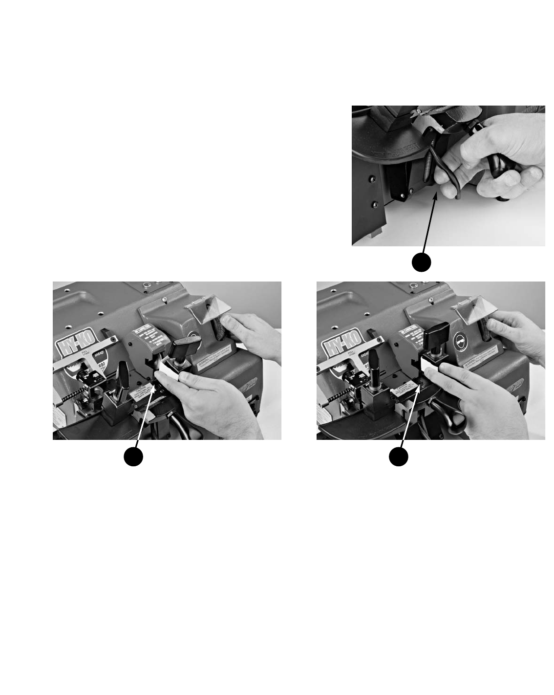
3) With your right hand, rotate the deburring brush up toward the back of the machine. The brush is mounted
on the same spindle as the cutter. Therefore, rotating the brush rotates the cutter.
4) To determine if an adjustment is necessary:
a) If the business card remains stationary as you rotate the cutter and brush up and only a light mark or no
mark is left on the back of the business card then NO adjustment is needed.
b) If the business card wants to move up as you rotate the cutter and brush up or there are individual teeth
marks in the back of the business card then the carriage stop is too close to the cutter and needs to be
adjusted outward.
c) If the business card wants to freely drop while you are rotating the cutter and brush up then the carriage
stop is too far away from the cutter and needs to be adjusted inward.
5) Lower the carriage back down to the locked down position.
1
3

28
Hy-Ko Products Company 330•467•7446 800•896•7890 Fax: 330•467•7442 E-Mail: [email protected] www.hykokeys.com
Carriage Stop Adjustment Instructions
1) Using an 11/32˝ open-ended wrench, loosen the
locking nut on the carriage stop screw by turning it
counterclockwise.
2) If the carriage is too close to the cutter, manually
turn the carriage stop screw counterclockwise to
increase the space between the right jaw and the cutter.
If the carriage is too far away from the cutter,
manually turn the carriage stop screw clockwise to
decrease the space between the right jaw and the cutter.
3) Using the 11/32˝ open-ended wrench, tighten the
locking nut of the carriage stop screw by turning it
clockwise to hold the screw in the desired position.
4) Repeat the steps in “How to Determine the Need for a Carriage Stop Adjustment” to see if more adjustments
are needed.
Spacing Calibration
The spacing is the distance, left-to-right between the cutter
and the tracer. This distance must match the distance of
the gauge fork inserts which are fixed and used to properly
space the keys. Since the gauge fork inserts and the cutter
are in fixed positions, the spacing is adjusted by moving the
tracer left or right as needed.
Spacing needs to be adjusted when a new cutter is installed
as well as periodically if a high volume of keys are duplicat-
ed on the machine.
Tools Needed for Spacing Calibration
3/16˝ allen wrench
How to Determine the Need for a
Spacing Adjustment
Note: FOR SAFETY, MAKE SURE THE MAIN
POWER IS OFF OR UNPLUG THE MACHINE
FROM ITS POWER SOURCE.
1) Select the standard jaw setting and align two identical
KW1 key blanks, upside down, in the jaws by their tips.
By putting the keys in upside down the tips will be
above the face of the jaw allowing it to be gauged by
that feature.
1
Spacing locking
screw
Spacing adjustment
dial

29
Hy-Ko Products Company 330•467•7446 800•896•7890 Fax: 330•467•7442 E-Mail: [email protected] www.hykokeys.com
5) To determine if an adjustment is necessary:
a) If you hear the cutter just touching the tip of the key blank in the right jaw and it is making a very slight
pinging sound only for a small portion of a full revolution while rotating the deburring brush up towards
the back of the machine, then NO adjustment is needed.
b) If you hear a heavy grinding sound on the tip of the key blank in the right jaw while rotating the debur-
ring brush up towards the back of the machine, then the spacing needs to be adjusted.
c) If you hear nothing at all when rotating the deburring brush up towards the back of the machine, then
the spacing needs to be adjusted.
Spacing Adjustment Instructions
1) Lower the carriage back down to the locked
down position.
2) Using a 3/16˝ allen wrench, loosen the screw on
top of the tower assembly. Just break it loose.
DO NOT remove the screw.
2) Make sure that the carriage is as far left as it will go and that the gauge fork is in the “up” position.
3) Raise the carriage until the tip of the key blank in the left jaw touches the flat, left side of the tracer.
Use your left hand on the jaw to maintain this contact.
4) While holding the keys in the jaws up to the tracer and cutter, rotate the deburring brush up toward the back
of the machine. The brush is mounted on the same spindle as the cutter. Therefore, rotating the brush rotates
the cutter.
3 4
2

30
Hy-Ko Products Company 330•467•7446 800•896•7890 Fax: 330•467•7442 E-Mail: [email protected] www.hykokeys.com
3) If a heavy grinding sound was heard, turn the spacing
adjustment dial clockwise. This will move the tracer to
the LEFT, farther away from the cutter.
If no sound was heard, turn the spacing adjustment
dial counterclockwise. This will move the tracer to the
RIGHT, closer to the cutter.
Note: It is recommended to only rotate the dial no
more than 2-4 marks on the dial at a time before
re-checking.
4) After making the adjustment, tighten the screw on top
of the tower assembly using the 3/16˝ allen wrench.
5) Go back to the section on “How to Determine the
Need for a Spacing Adjustment” to see if you need to
make any further adjustments.
Depth Calibration
The depth is the distance, in-and-out, that the tracer is
compared to the cutter. This distance must match to have
keys cut to the proper depth. The depth is adjusted by
moving the tracer in or out as needed.
Depth needs to be adjusted when a new cutter is installed
as well as periodically if a high volume of keys are dupli-
cated on the machine. Depth is the most likely adjustment
that will be needed as keys are cut. As a cutter is used it
wears and will get smaller in diameter. The tracer will
have to be moved to compensate for this.
Tools Needed for Spacing Calibration
1/8˝ allen wrench
How to Determine the Need for a
Depth Adjustment
Note: FOR SAFETY, MAKE SURE THE MAIN
POWER IS OFF OR UNPLUG THE MACHINE
FROM ITS POWER SOURCE.
1) Select the standard jaw setting and place two identical
KW1 key blanks, as you would normally, in the jaws.
The keys do not need to be gauged by the gauge fork,
as long as they are in relatively similar positions in
the jaws.
1
Depth
locking screw
Depth adjustment
dial
Spacing adjustment
dial

31
Hy-Ko Products Company 330•467•7446 800•896•7890 Fax: 330•467•7442 E-Mail: [email protected] www.hykokeys.com
2) Move the carriage all the way to the left by pushing down on the carriage handle to the left.
3) Raise the carriage by unlocking it using the trigger. Fully squeeze the trigger to allow the roller bearing to go
under the pressure plate.
4) Guide the roller bearing under the pressure plate
while keeping the carriage pulled back slightly so
the keys do not touch the cutter and tracer.
Note: You want to position the key in the left jaw
so that the tracer touches the key close to, but
not touching the shoulder. An exact position
is not necessary. You will be checking along
different parts of the key.
3
3
5) Since the keys in the carriage are being held up to
the tracer and cutter there is no reason to hold it.
Use your right hand to rotate the deburring brush
up toward the back of the machine. The brush is
mounted on the same spindle as the cutter.
Therefore, rotating the brush rotates the cutter.
4
5

32
Hy-Ko Products Company 330•467•7446 800•896•7890 Fax: 330•467•7442 E-Mail: [email protected] www.hykokeys.com
6) To determine if an adjustment is necessary:
a) If you hear the cutter just touching the edge of the key blank in the right jaw and it is making a very
slight pinging sound only for a small portion of a full revolution while rotating the deburring brush up
towards the back of the machine, then NO adjustment is needed.
b) If you hear a heavy grinding sound on the edge of the key blank in the right jaw while rotating the debur-
ring brush up towards the back of the machine, then the spacing needs to be adjusted.
c) If you hear nothing at all when rotating the deburring brush up towards the back of the machine, then
the spacing needs to be adjusted.
7) To check in another spot on the key, pull back
slightly on the carriage just enough so that the
keys are not touching the cutter and tracer. Use
the carriage handle on the left to then move to a
new spot on the keys for checking.
Note: It is always good to check on two or three
spots along the blade of the key. If you there is a
noticeable difference when checking, such as one
spot has a heavy grinding and another spot there
is no sound, then check to make sure that the
keys are seated flat in the jaws and that the jaws
are seated properly on the jaw seat.
Depth Adjustment Instructions
1) Lower the carriage back down to the locked down
position.
2) Using a 1/8˝ allen wrench, loosen the screw on the
left side of the tower assembly. Just break it loose.
DO NOT remove the screw.
3) If a heavy grinding sound was heard, turn the
depth adjustment dial to the right. This will move
the tracer farther OUT of the tower assembly
which in turn will move the key in the right jaw
farther away from the cutter.
If no sound was heard, turn the depth adjustment
dial to the left. This will move the tracer farther
IN the tower assembly, which in turn will move
the key in the right jaw closer to the cutter.
Note: It is recommended to only rotate the dial
no more than 2-4 marks on the dial at a time
before re-checking.
7
2
3

33
Hy-Ko Products Company 330•467•7446 800•896•7890 Fax: 330•467•7442 E-Mail: [email protected] www.hykokeys.com
4) After making the adjustment, tighten the screw on top of the tower assembly using the 3/16˝ allen wrench.
5) Go back to the section on “How to Determine the Need for a Depth Adjustment” to see if you need to make
any further adjustments.
Testing for Calibration Accuracy
To ensure that the adjustments made to the machine are accurate, the following steps are advised.
1) Locate a new, “quality” padlock key and make a duplicate key of the original key following the instructions
in this manual.
Note: For this test, duplicating the key in the automatic mode is preferred since the feed and speed are
controlled.
2) Insert the newly cut key in the lock to ensure it works. It should operate smoothly with no hesitation.
Note: If the first key did not work, try cutting another key. The calibration may be OK. The key may have
been miscut due to gauging. Take your time to properly gauge the key and try again.
How to Replace the Deburring Brush
There is no warranty on the deburring brush. Therefore it should be treated with care just like the cutter. It will
wear down with usage. A newly cut key only needs a “light brushing”. Pressing harder will only cause the brush
to wear down quicker. When the bristles extend only 1/4˝ from the hub, it is time to replace the brush.
Tools Needed for Spacing Calibration
5/32˝ allen wrench
1/2˝ open-ended wrench – qty. 2
Deburring Brush Replacement Instructions
Note: FOR SAFETY, MAKE SURE THE MAIN
POWER IS OFF OR UNPLUG THE MACHINE
FROM ITS POWER SOURCE.
1) Using a 5/32˝ allen wrench, remove the screw
attaching the brush guard assembly to the
machine housing.
1

34
Hy-Ko Products Company 330•467•7446 800•896•7890 Fax: 330•467•7442 E-Mail: [email protected] www.hykokeys.com
2) Remove the brush guard assembly.
3) Position the 1/2˝ open-ended wrench on the flat
surfaces of the spindle closest to the brush. Keep
pressure on it by pushing to the back to keep it
from turning.
4) Position the other 1/2˝ open-ended wrench on the
brush bolt and turn it counterclockwise to loosen it.
5) Manually unscrew the brush bolt and remove
the bolt and washer.
6) Remove and discard the worn brush.
7) Install the new brush. It does not matter which way
it goes on. Then replace the washer and the brush bolt.
8) Use the two 1/2˝ open-ended wrenches to securely tighten the brush bolt.
9) Replace the brush guard assembly.
10) Using a 5/32˝ allen wrench, tighten the screw to secure the brush guard assembly to the key machine.
9
10
2
4
3
Washer
Deburring Brush
Brush
bolt

35
Hy-Ko Products Company 330•467•7446 800•896•7890 Fax: 330•467•7442 E-Mail: [email protected] www.hykokeys.com
Troubleshooting Guide
The following are possible issues and solutions that may or may not be relevant to your situation. For further
assistance, please contact Customer Service.
ISSUE: The cutter and brush run constantly when the main power is on. The only way to stop the cutter
and brush is to turn the main power off.
SOLUTION: The brush switch needs to be replaced. It is a momentary (spring-loaded) switch that is fused in the
‘ON’ position which makes the key machine think that someone is constantly pressing the switch.
Sometimes it will feel sticky or sluggish and will not spring back to the ‘OFF’ position. This is
because shavings or dirt could have built up behind the switch. It is part number KZ-MP0038. It is
very easy to replace the switch out in the field. Just remove the 4 screws on the front switch panel
and carefully pull out the panel to expose the back of the switches. Disconnect the old brush switch
making sure to remember the order of the wires. Pop out the old switch by pressing the tabs and
then snap in the new switch. Replace the wires in the correct order. Finally, mount the switch plate
back onto the key machine.
KZ-MP0038 - Brush switch

36
Hy-Ko Products Company 330•467•7446 800•896•7890 Fax: 330•467•7442 E-Mail: [email protected] www.hykokeys.com
Troubleshooting Guide
ISSUE: When bringing up the carriage to cut a key the vacuum turns on but the cutter and brush will not
turn. Also, pressing the brush switch does not turn on the cutter and brush. The machine does
have power to the unit shown by the red light on top when the main power button is on.
SOLUTION: This is due to someone “cold starting” the machine. Someone has brought a key up against the
cutter and then turned on the main power. The thermal overload switch has been popped on the
main motor. They need to remove the white plastic cap on the back of the machine and press the
rubber button inside the machine. It can be very hard to push in sometimes. The back end of a
Sharpie pen or something else blunt may help. The more that the switch is popped the harder it
will be to reset eventually causing the motor to burn up. The thermal overload switch is sometimes
confused with the breaker on the back panel. That is only for when there is no power at all to the
machine. If there is power to the machine, the red light will be illuminated on the top of the
machine when the main power is on.
When standing in front of the key machine, the motor reset button is located around the back-left side. It is not
on the back switch plate where the vacuum plugs in and the power cord enters the machine. That is the location
of a 15 amp breaker.
Remove the white cap Motor reset button

37
Hy-Ko Products Company 330•467•7446 800•896•7890 Fax: 330•467•7442 E-Mail: [email protected] www.hykokeys.com
Troubleshooting Guide
ISSUE: The jaws keep sticking and won’t come apart. They have to get a screwdriver to pry them apart.
This is caused by someone opening up the jaws too much so that the top and bottom jaws are
completely apart on the jaw assembly. Then when they try to tighten them back down they are not
completely aligned and as the jaws are aligned by the pressure of tightening down, a small burr is
created as the top jaw fits over the bottom jaw.
SOLUTION: Pry apart the jaws using one or two screwdrivers. Once they are apart take a small file and file the
four edges as noted on the following drawing which can be faxed to the customer. Just go over the
edges lightly to take off any slight burr that may be there. Wipe the jaws completely clean and put
a very light coat of white lithium grease on the inside walls of the top jaws. Re-assemble the jaws.

38
Hy-Ko Products Company 330•467•7446 800•896•7890 Fax: 330•467•7442 E-Mail: [email protected] www.hykokeys.com
Troubleshooting Guide
ISSUE: The machine seems to have lost tension when cutting a key. The cutter just skims across the key
and does not go all the way down into the cuts. It will cut fine in manual and semi-automatic
mode, but not automatic.
SOLUTION: The cutter is probably very dull. The reason it works in manual and semi-automatic modes is
because the person is applying extra pressure on the carriage to compensate for the dull cutter.
They should put on a new cutter and re-calibrate the machine. If the cutter is fairly new it probably
hit the jaw causing it to become dull prematurely. A new cutter will have to be put on with
particular attention paid to the carriage stop adjustment. It is extremely rare that the carriage
spring (KZ-MP0174) has lost tension. If they say that they can get it to cut a key in manual or
semi-automatic mode by applying more pressure, then it is the cutter that needs to be replaced.
Carriage spring at rest Carriage spring engagedPROMATIC-100 Cutter
Part No. KMC8

39
Hy-Ko Products Company 330•467•7446 800•896•7890 Fax: 330•467•7442 E-Mail: [email protected] www.hykokeys.com
Troubleshooting Guide
ISSUE: The customer can hear the cam motor running but it doesn’t push the carriage over to the left.
This issue can be determined by noticing that the green light on top of the key machine stays on
and the cam does not move the carriage over at all.
SOLUTION: The gear in the cam motor is stripped not allowing the cam to turn. The cam motor assembly will
have to be replaced. The part number is KZ-SA0008. This probably occurred when the carriage
handle on the left of the machine was blocked from going down as the carriage moved to the left.
This put pressure on the cam and ultimately stripped the cam motor gear. The cam motor assem-
bly is located just behind the front switch plate. Flip the machine up on its back side. Take the
bottom cover off the machine using a 9/64˝ allen wrench and disconnect the white plug between the
blue and yellow wires leading to the cam motor from the wiring harness. Remove the two flat-head
hex screws on the outside, right-hand side of the machine using a 3/32˝ allen wrench. The assem-
bly will come out completely. It may help to remove the four screws on the front switch plate and
allow it to come forward, out of the machine to give more room for removing the old cam motor
assembly and installing the new one.
White plug to disconnect Cam Motor Assy.
Part No. KZ-SA0008
Mounting screws
Front switch plate
Cam motor
assembly

40
Hy-Ko Products Company 330•467•7446 800•896•7890 Fax: 330•467•7442 E-Mail: [email protected] www.hykokeys.com
Troubleshooting Guide
ISSUE: The cam motor keeps spinning constantly when the machine is turned on causing it to push the
carriage over to the left. To get it to stop they have to turn the machine off at the end of the cam
cycle so they can start the next key without the cam being in the way. This issue can be determined
by noticing that the green light on top of the key machine stays on and the cam is spinning causing
it to get in the way of the carriage.
SOLUTION: The microswitch is out of adjustment. They can adjust the microswitch easily by first removing the
cam motor assembly. To do this, move the carriage all the way to the left, unplug the machine and
then flip it up on its back. Take the bottom cover off the machine using a 9/64˝ allen wrench and
disconnect the white plug between the blue and yellow wires leading to the cam motor from the
wiring harness. Remove the two flat-head hex screws on the outside, right-hand side of the
machine using a 3/32˝ allen wrench. The assembly will come out completely. It may help to
remove the four screws on the front switch plate and allow it to come forward, out of the machine
to give more room for removing the old cam motor assembly and installing the new one. Use a
needle-nose pliars and carefully bend the roller arm slightly up towards the cam. When you rotate
the cam around the microswitch it will click when it is just over halfway up the hill of the cam
which is the end of the cycle. You can test it by plugging it in and running it before putting it back
in the machine. Do this by holding onto the main assembly bracket so as not to interfere with the
rotating cam while it is running.
Hill on cam
ALSO REFER TO
PICTURES ON
PREVIOUS ISSUE
Bend roller arm
up slightly

41
Hy-Ko Products Company 330•467•7446 800•896•7890 Fax: 330•467•7442 E-Mail: [email protected] www.hykokeys.com
Troubleshooting Guide
ISSUE: After cutting a key in automatic or semi-automatic mode the key machine does not stop running.
However, it will turn off when brought down after cutting a key in manual mode.
SOLUTION: When standing in front of the key machine, the motor reset button is located around the back-left
side. It is not on the back switch plate where the vacuum plugs in and the power cord enters the
machine. That is the location of a 15 amp breaker.
Back view Front view
Possible point
of contact
interference
Possible point
of contact
interference
ISSUE: After cutting a key in automatic mode, the carriage will not move back to the right so they can set
up to cut another key.
SOLUTION: The main power may have been turned off before the cam motor finished going back to its home
position. While watching the green light on top of the key machine, turn the main power on. The
green light will probably turn on for a second or two before going back out. Once it goes out, the
carriage should be able to go back to the right so they can cut another key.
Turn the main power back on while… …watching for the green light

42
Hy-Ko Products Company 330•467•7446 800•896•7890 Fax: 330•467•7442 E-Mail: [email protected] www.hykokeys.com
Troubleshooting Guide
ISSUE: If you notice that when the carriage is down and you move it left or right, with the handle at the
left, the carriage will jump or make a weird noise. It doesn’t travel smoothly.
SOLUTION: The carriage has a rubber bumper on the back side of it towards the bottom. This is dragging on
the wall of the key machine casting. There is nothing wrong with it. If they want to move more
smoothly, bring the carriage up just a little bit and the rubber bumper will not be touching anymore.
ISSUE: The trigger broke off and needs to be replaced.
SOLUTION: You must remove the portion that is in the left in the cam block. You can do this by removing the
front plate on the carriage. To get the carriage up, as if you were going to start it in the automatic
cycle, pull up on the nut. Once the roller bearing is under the pressure plate, you can unscrew the
nut and remove what is left of the trigger. Once you remove the what is left of the trigger you can
temporarily use a 1/4-20 bolt until the new trigger arrives. The part number for the new trigger is
KZ-MP0138 and the nut to lock it down is KZ-MP0142.
KZ-MP0142
Nut
KZ-MP0138
Trigger
Rubber bumper
located on back
side of carriage

43
Hy-Ko Products Company 330•467•7446 800•896•7890 Fax: 330•467•7442 E-Mail: [email protected] www.hykokeys.com
Express Limited Warranty-U.S. only
The express limited warranty set forth below is given by Hy-Ko Products Company (Hy-Ko) with respect to the Hy-Ko
brand key machine that you have purchased, when purchased and used in the United States. The product that you have
purchased is the only product to which this warranty card and the limited warranty provided by Hy-Ko and stated on the
card apply.
Your product, when delivered to you in new condition in its original container, is expressly warranted against defects in
materials and workmanship as follows: for a period of 18 months from the date of original purchase, defective parts or a
defective product returned to a Hy-Ko repair facility, upon inspection, will be exchanged for new or comparable rebuilt
parts, or a refurbished product, as determined by the Hy-Ko repair facility. Warranty repair or replacement shall not
extend the original warranty period of the defective product. This express limited warranty does not cover any supplies
or accessories, as to which there shall be no warranty or replacement.
This express limited warranty covers defects encountered in normal use of the product, and does not apply in the follow-
ing cases:
(a) Loss of or damage to the product due to abuse, mishandling, improper packing by you, alteration, accident, electrical
current fluctuations, failure to follow operating and maintenance operations prescribed in Hy-Ko’s key machine manual,
or service performed by someone other than a Hy-Ko repair facility.
(b) Use of parts or supplies (other than those sold by Hy-Ko) that cause damage to the product or cause abnormally
frequent service calls or service problems.
(c) If the product has had its serial number or dating altered or removed.
NO IMPLIED WARRANTY, INCLUDING ANY IMPLIED WARRANTY OF MERCHANTABILITY OR FITNESS FOR A
PARTICULAR PURPOSE, APPLIES TO THE PRODUCT AFTER THE APPLICABLE PERIOD OF THE EXPRESS LIMITED
WARRANTY STATED ABOVE, AND NO OTHER EXPRESS WARRANTY OR GUARANTY, EXCEPT AS MENTIONED ABOVE,
GIVEN BY ANY PERSON OR ENTITY WITH RESPECT TO THE PRODUCT SHALL BIND HY-KO. (SOME STATES DO
NOT ALLOW LIMITATIONS ON HOW LONG AN IMPLIED WARRANTY LASTS, SO THE ABOVE LIMITATION MAY NOT
APPLY TO YOU.) HY-KO SHALL NOT BE LIABLE FOR LOSS OF REVENUES OR PROFITS, INCONVENIENCE,
EXPENSE FOR SUBSTITUTE EQUIPMENT OR SERVICE, STORAGE CHARGES, OR ANY OTHER SPECIAL, INCIDENTAL
OR CONSEQUENTIAL DAMAGES CAUSED BY THE USE OR MISUSE OF, OR INABILITY TO USE THE PRODUCT,
REGARDLESS OF THE LEGAL THEORY ON WHICH THE CLAIM WAS BASED, AND EVEN IF HY-KO WAS ADVISED OF
THE POSSIBILITY OF SUCH DAMAGES, IN NO EVENT SHALL RECOVERY OF ANY KIND AGAINST HY-KO BE
GREATER IN AMOUNT THAN THE PURCHASE PRICE OF THE PRODUCT SOLD BY HY-KO WHICH CAUSED THE
ALLEGED DAMAGE.
WITHOUT LIMITING THE FOREGOING, YOU ASSUME ALL RISK AND LIABILITY FOR THE LOSS, DAMAGE OR INJURY
TO YOU AND YOUR PROPERTY AND TO OTHERS AND THEIR PROPERTY ARISING OUT OF USE OR MISUSE OF, OR
INABILITY TO USE THE PRODUCT NOT CAUSED DIRECTLY BY THE NEGLIGENCE OF HY-KO. (SOME STATES DO
NOT ALLOW THE EXCLUSION OR LIMITATION OF INCIDENTAL OR CONSEQUENTIAL DAMAGES, SO THE ABOVE
EXCLUSION OR LIMITATION MAY NOT APPLY TO YOU.) THIS LIMITED WARRANTY SHALL NOT EXTEND TO
ANYONE OTHER THAN THE ORIGINAL PURCHASER OF THE PRODUCT.

Hy-Ko Products Company
800-896-7890
KZ-MP0161 0310
