
DOT HS 812 513 December 2018
Aftermarket Safety Device
Driver Vehicle Interface
Guidance Development

i
Technical Report Documentation Page
1. Report No.
DOT HS 812 513
2. Government Accession No.
3. Recipient’s Catalog No.
4. Title and Subtitle
Aftermarket Safety Device Driver Vehicle Interface Guidance Development
Draft Final Report
5. Report Date
December 2018
6. Performing Organization Code
7. Author(s)
Neil Lerner, Dawn Marshall, Timothy Brown, Jeremiah Singer, Zachary
Calo
8. Performing Organization Report
9. Performing Organization Name and Address
Westat
1600 Research Boulevard
Rockville, Maryland 20850-3129
10. Work Unit No. (TRAIS)
11. Contract or Grant No.
DTNH2211R00237L/0015
12. Sponsoring Agency Name and Address
United States Department of Transportation
National Highway Traffic Safety Administration
1200 New Jersey Ave., SE
Washington, DC 20590
13. Type of Report and Period Covered
Draft final report / Sept. 2015 – May
2017
14. Sponsoring Agency Code
15. Supplementary Notes
Christian Jerome (COTR/TO)
16. Abstract
Connected vehicle technology allows equipped vehicles to communicate their position and movement with other
equipped vehicles, enabling the provision of safety warnings for a variety of potential collision scenarios. CV devices
can be installed as original equipment in new vehicles, but they can also be installed in existing vehicles as
aftermarket safety devices (ASDs). ASDs can help to accelerate the rate of CV technology adoption, which is
important for CV functionality, but they also raise distinct questions about interface considerations and the potential
need for access to vehicle onboard data. This study addressed these questions through a series of research tasks. An
information search and review found that ASD development is still in an early stage and there is little consensus
regarding what ASDs are likely to look like when they become available to the public. There is also disagreement
regarding the need for access to onboard CAN bus data and professional installation. An analytical task was
conducted to identify the data elements that might not be available to an ASD without a data connection to the
vehicle itself. Results showed that lack of access to vehicle data could limit the data available toASDs in a number of
ways, and that two elements required for all CV devices (transmission state and steering wheel angle) are not
inherently available to an ASD without a vehicle data connection. Following the analytical review, researchers
developed three mock prototype ASD systems representing a range of design approaches for use in subsequent
experiments. Level 1 was auditory only. Level 2 had an auditory warning with a small visual display device located
on the vehicle dashboard that indicted threat direction. Level 3 represented a vehicle-integrated system with light bars
located around the perimeter of the vehicles that flashed to indicate threat direction. A driving simulator experiment
focused on driver response to collision warnings found that participants generally responded quickly to ASD
warnings, and in some collision scenarios, the Level 3 interface led to faster responding than the other two interfaces.
17. Key Words
18. Distribution Statement
No restrictions. This document is available to the public
through the National Technical Information Service,
www.ntis.gov.
19. Security Classif. (of this report)
Unclassified
20. Security Classif. (of this page)
Unclassified
21. No. of Pages
121
22. Price
N/A
Form DOT F 1700.7 Reproduction of completed page authorized.
ii
Table of Contents
List of Figures v
List of Tables vii
List of Acronyms ........................................................................................................................ viii
Executive Summary ..................................................................................................................... ix
1. Introduction ........................................................................................................ 1
1.1 Background ..................................................................................................................... 1
1.2 Objectives ........................................................................................................................ 2
2. Information Search and Review ....................................................................... 3
2.1 Overview of Connected Vehicle Approaches Considered in Review ........................ 3
2.2 Methods for Search and Review ................................................................................... 5
2.3 Aftermarket Device Products and Features ................................................................ 7
2.4 Connected Vehicle DVI Research and Design ............................................................. 9
2.4.1 ASD DVIs ................................................................................................................................ 10
2.4.2 General DVI Considerations for CV ........................................................................................ 13
2.5 Aftermarket Safety Device Industry Trends ............................................................. 18
2.6 Challenges and Knowledge Gaps ................................................................................ 19
3. Relation to Onboard Data Sources ................................................................. 25
3.1 Key Onboard Variables ............................................................................................... 25
3.2 System Performance Aspects and Associated Behavioral Outcomes ...................... 25
3.3 Mapping of Onboard Variables to System Performance Aspects ........................... 26
4. Driving simulator study ................................................................................... 36
4.1 Hypotheses .................................................................................................................... 36
4.2 Method........................................................................................................................... 36
4.2.1 Safety Applications .................................................................................................................. 36
4.2.2 ASD DVIs ................................................................................................................................ 37
iii
4.2.3 Apparatus ................................................................................................................................. 40
4.2.4 CV Safety Applications ............................................................................................................ 41
4.2.5 Presence of Onboard Data ........................................................................................................ 42
4.2.6 Driving Scenarios ..................................................................................................................... 42
4.2.7 Practice Drive ........................................................................................................................... 43
4.2.8 Study Drives ............................................................................................................................. 43
4.2.9 Sampling and Participant Recruitment ..................................................................................... 43
4.2.10 Independent Variables ............................................................................................................ 44
4.2.11 Dependent Measures .............................................................................................................. 44
4.2.12 Experimental Procedure ......................................................................................................... 46
4.2.13 Debrief.................................................................................................................................... 46
4.2.14 Data Handling ........................................................................................................................ 46
4.2.15 Data Analysis and Statistical Modeling ................................................................................. 47
4.2.16 Alert Suppression Using Vehicle Onboard Data .................................................................... 47
4.3 Intersection Movement Assist Scenario ..................................................................... 48
4.3.1 Specific Method ....................................................................................................................... 48
4.3.2 Results ...................................................................................................................................... 50
4.4 Left Turn Assist Scenario ............................................................................................ 57
4.4.1 Specific Method ....................................................................................................................... 57
4.4.2 Results ...................................................................................................................................... 61
4.5 EEBL Scenario ............................................................................................................. 68
4.5.1 Specific Method ....................................................................................................................... 68
4.5.2 Results ...................................................................................................................................... 71
4.6 Driving Simulator Study Summary ............................................................................ 75
5. General Discussion and Limitations............................................................... 80
5.1 General Discussion ....................................................................................................... 80
5.2 Study Limitations ......................................................................................................... 81
References 83
Appendix A: Simulator Experiment Phone Screening ...................................................... A-1
Appendix B: Simulator Experiment Informed Consent ................................................... B-1
Appendix C: Simulator Experiment Demographic and Driving Questionnaire ............ C-1
iv
Appendix D: Simulator Experiment Post Drive Questionnaire ....................................... D-1
Appendix E: Simulator Experiment Wellness Survey ...................................................... E-1
Appendix F: Simulator Experiment Realism Survey ........................................................ F-1
Appendix G: Simulator Experiment Debriefing Statement .............................................. G-1
v
List of Figures
Figure 1. Illustration of ASD components (from Cohda Wireless, 2015) ...................................... 8
Figure 2. Directional visual icons ................................................................................................. 38
Figure 3. Level 2 (audio-visual) display on simulator dash to right of steering wheel ................ 38
Figure 4. Level 3 (integrated display) with “left” warning displayed .......................................... 39
Figure 5. Reference for alert display in cab model ....................................................................... 40
Figure 6. miniSim driving simulator ............................................................................................. 41
Figure 7. Timing of IMA scenario ................................................................................................ 48
Figure 8. IMA scenario at point when incursion vehicle becomes visible ................................... 49
Figure 9. Accelerator pedal release time from visible for IMA event .......................................... 51
Figure 10. Brake response time from visible for IMA event ........................................................ 52
Figure 11. Steering response time from visible for IMA event .................................................... 53
Figure 12. First response time from visible for IMA event .......................................................... 54
Figure 13. “Did you know what sort of event the warning was trying to alert you to before you
saw the other vehicle?” for IMA event ......................................................................................... 55
Figure 14. “How easily and quickly could you interpret this warning?” for IMA event ............. 55
Figure 15. “How useful was the warning to you in this situation?” for IMA event ..................... 56
Figure 16. “How distracting was this warning?” for IMA event .................................................. 56
Figure 17. “Would you pay to have this type of system installed in your vehicle?” for
IMA event ..................................................................................................................................... 57
Figure 18. “If yes, how much (in dollars)?” for IMA event ......................................................... 57
Figure 19. Timing of LTA scenario .............................................................................................. 58
Figure 20. LTA scenario at point when alert is issued ................................................................. 59
Figure 21. LTA scenario at point where incursion vehicle becomes visible ................................ 60
Figure 22. Accelerator pedal release time from visible for LTA event ........................................ 62
Figure 23. Brake application response time from visible for LTA event ..................................... 63
Figure 24. Steering response time from visible for LTA event .................................................... 64
Figure 25. First response time from visible for LTA event .......................................................... 65
Figure 26. “Did you know what sort of event the warning was trying to alert you to before you
saw the other vehicle?” for LTA event ......................................................................................... 66
Figure 27. “How easily and quickly could you interpret this warning?” for LTA event ............. 66
vi
Figure 28. “How useful was the warning to you in this situation?” for LTA event ..................... 67
Figure 29. “How distracting was this warning?” for LTA event .................................................. 67
Figure 30. “Would you pay to have this type of system installed in your vehicle?” for
LTA event ..................................................................................................................................... 68
Figure 31. “If yes, how much (in dollars)?” for LTA event ......................................................... 68
Figure 32. Diagram of EEBL scenario ......................................................................................... 69
Figure 33. Timing of EEBL scenario ............................................................................................ 69
Figure 34. EEBL scenario when alert is issued ............................................................................ 70
Figure 35. Accelerator pedal release time for EEBL event .......................................................... 71
Figure 36. Brake response time from visible for EEBL ............................................................... 72
Figure 37. “Did you know what sort of event the warning was trying to alert you to before you
saw the other vehicle?” for EEBL event ....................................................................................... 73
Figure 38. “How easily and quickly could you interpret this warning?” for EEBL event ........... 73
Figure 39. “How useful was the warning to you in this situation?” for EEBL event ................... 74
Figure 40. “How distracting was this warning?” for EEBL event ................................................ 74
Figure 41. “Would you pay to have this type of system installed in your vehicle?” for
EEBL event ................................................................................................................................... 75
Figure 42. “If yes, how much (in dollars)?” for EEBL event ....................................................... 75
vii
List of Tables
Table 1. Aftermarket device types (from Harding et al., 2014) ...................................................... 5
Table 2. On board variable categories and subcategories ............................................................. 25
Table 3. Mapping of behavioral effects to system performance limitations ................................. 28
Table 4. Mapping of onboard data elements to CV system performance aspects for IMA and
LTA applications .......................................................................................................................... 30
Table 5. Experimental conditions ................................................................................................. 41
Table 6. Implications of onboard data when present .................................................................... 42
Table 7. CV warning presentation conditions............................................................................... 42
Table 8. Participant distribution across experimental conditions ................................................. 44
Table 9. Dependent measures ....................................................................................................... 45
Table 10. Dependent variables for each event .............................................................................. 47
Table 11. Participant gender for each ASD DVI level for the IMA scenario ............................... 49
Table 12. Crashes for each display type in the IMA event ........................................................... 50
Table 13. Number of accelerator pedal release responses by display type for IMA event ........... 50
Table 14. Number of brake responses by display type for IMA event ......................................... 51
Table 15. Number of steering responses by display type for IMA event ..................................... 52
Table 16. Number of accelerator pedal application responses by display type for IMA event .... 53
Table 17. Number of first responses by display type for IMA event ........................................... 54
Table 18. Participant gender for each ASD DVI level for the LTA scenario ............................... 60
Table 19. Crashes for each display type in the LTA event ........................................................... 61
Table 20. Number of accelerator pedal release responses by display type for LTA event ........... 61
Table 21. Number of brake responses by display type for LTA event ......................................... 62
Table 22. Number of steering responses by display type for LTA event ..................................... 63
Table 23. Number of accelerator pedal application responses by display type for LTA event .... 64
Table 24. Number of first responses by display type for LTA event ........................................... 65
Table 25. Participant gender for each ASD DVI level for the EEBL scenario ............................ 70
Table 26. Crashes for each display type in the EEBL event ......................................................... 71
Table 27. Total number of collisions for each event and interface ............................................... 77
viii
List of Acronyms
AAM: Alliance of Automobile Manufactures
ASD: Aftermarket safety device
BSM: Basic safety message
BSW: Blind spot warning
CCC: Car Connectivity Consortium
CV: Connected Vehicle
CVRIA: Connected Vehicle Reference Implementation Architecture
DNPW: Do not pass warning
DSRC: Dedicated short range communication
DVI: Driver-vehicle interface
EEBL: Emergency electronic brake light
FCW: Forward collision warning
HFCV: Human Factors for Connected Vehicles
HUD: Head up display
IMA: Intersection movement assist
LCW: Lane change warning
LTA: Left turn assist
NHTSA: National Highway Traffic Safety Administration
OBU: On board unit
OEM: Original equipment manufacturer
RSD: Retrofit safety device
TEOD: Time eyes on display
USDOT: United States Department of Transportation
V2I: Vehicle to infrastructure
V2V: Vehicle to vehicle
V2X: Vehicle to everything
VAD: Vehicle awareness devices

ix
Executive Summary
Introduction
Connected Vehicle (CV) technology enables rapid wireless communications among individual
vehicles, the transportation infrastructure, and other entities. A key application of CV technology
is the communication of safety messages to drivers when potential conflicts between vehicles are
emerging. CV technology removes the limitations of being able to detect emerging threat
situations solely from onboard sensors and can detect potential conflicts without direct line-of-
sight between vehicles. CV technology has great potential to reduce the types of collisions that
cause the most deaths on U.S. highways (Harding et al., 2014), but certain implementation
factors are necessary to ensure successful deployment. First, because vehicle-to-vehicle (V2V)
communication requires both vehicles to be CV-equipped, a substantial number of CV devices
must be deployed. Without substantial fleet penetration, it will be rare that potentially conflicting
vehicles will both be CV-equipped and able to communicate to one another. Second, the CV
interface must provide accurate and timely information that helps drives to take appropriate
action to avoid collisions.
CV devices use dedicated short-range communication (DSRC) technology to provide short- to
medium-range communication between vehicles and other road entities. The core data set
communicated via DSRC for safety functions is known as the basic safety message (BSM), and
is specified in SAE J2735. The BSM contains two parts. Part 1 consists of variables related to
vehicle position (longitude, latitude, etc.), vehicle motion (speed, heading, acceleration, etc.), and
vehicle size (length width). Part 2 consists of vehicle safety flags (ABS activation, wiper status,
hard braing, etc.) All CV devices must include all Part 1 elements, but Part 2 elements may vary
by vehicle model.
While the above issues are applicable to CV technology in general, they are especially relevant
to aftermarket safety devices (ASDs). ASDs are CV devices that are installed in vehicles that do
not include CV as original equipment. ASDs can help to enhance the efficacy of CV
communications by increasing the rate of CV technology adoption and fleet penetration to higher
levels than can be achieved by the sale of new vehicles alone.
Harding et al. (2014) define three types of aftermarket CV devices:
1. Vehicle awareness devices (VAD) are stand-alone devices that connect to the vehicle only
for power. They do not have a user interface; they only provide the BSM to other
vehicles.
2. Self-contained ASDs are like VADs, but also receive BSMs from other vehicles to
support safety applications for the driver of the equipped vehicle.
3. Retrofit safety devices (RSD) are similar to self-contained ASDs, but require a connection
to the vehicle’s data bus to incorporate onboard vehicle data.
Self-contained ASDs (heretofore referred to simply as ASDs) are the focus of this project. While
ASDs are likely to be an important part of the initial rollout of CV technology, they also have
some distinct issues that must be addressed. For example, ASDs have limited access to onboard
vehicle data relative to original equipment manufacturer (OEM) CV systems and retrofit
systems, and the lack of vehicle data might influence the functionality of ASDs. ASDs might
also have different interface characteristics and capabilities than an integrated OEM system.

x
Ultimately, ASDs will provide the greatest safety benefit if they are plentiful, function reliably
for a wide range of V2V safety applications, and use driver-vehicle interfaces (DVIs) that
promote rapid and proper responses to warnings without causing distraction, confusion, or
frustration.
The purpose of this project was to increase understanding of ASD human factors issues,
including identifying limitations and gauging the effectiveness of the ASD driver vehicle
interface. The objectives as stated in the contract Statement of Work were:
• Support the Human Factors Connected Vehicle (HFCV) research program by conducting
research that will examine the ASD DVI in the areas of human factors, systems design,
and system performance. Some of the research results will feed into the next generation
HFCV Principles, which is the primary product of the HFCV Program.
• Increase understanding of human factors issues, including identifying limitations and
gauging the effectiveness of the ASD DVI.
• Obtain data and results to support NHTSA’s HFCV program.
In order to achieve the project objectives, the following sequence of project activities was
implemented.
• Focused review of literature related to DVI, with particular interest in aftermarket
products
• Identification and description of available and planned product information, from
manufacturer web sites and others sources
• Interviews with industry experts
• Analytic assessment of potential functional impact if certain data elements are not
available to an ASD (i.e., no connection to vehicle data bus).
• Development of research plans to address key issues identified in the review and analysis
• Implementation and conduct of simulator experiment
Information Search and Review
This project included a range of tasks to investigate issues related to ASD interfaces. The initial
research task was an information search and review that included a review of literature, products,
and ASD design concepts. This task also included contacts with experts and technology
developers working on ASD hardware and interfaces. The review found that ASDs are still early
in development, and the few systems that have been developed are in experimental or prototype
form. The review of literature, products, and industry expert contacts indicated that there was no
clear trend or consensus in terms of expectations for future development of ASDs. Experts also
disagreed regarding whether or not ASDs would require professional installation and connection
to the vehicle’s onboard data for adequate functionality and performance.
Relation to Onboard Data Sources
As noted above, there is a debate among CV developers and researchers regarding whether an
ASD can perform adequately if installed as a stand-alone device, without access to the vehicle’s
onboard data via the CAN bus. The research team conducted an analytic task to determine the

xi
types of data that might or might not be available to an ASD, depending on the implementation
model, and the potential implications of these data types’ availability or unavailability. The
objective of this task was to identify the various types of data that may or may not be available to
an ASD from the device itself or from the vehicle, then determine the potential effects of a lack
or impairment of that data type on ASD capability or performance, or driver behavior. The full
set of CV data elements specified in SAE J2735 was used as a starting point. The high-level
categories of onboard information type were Vehicle State, Roadway/Environment State, Driver
State, Driver Intention, and External Object Detection. For each data element, the research team
considered the potential effect of its unavailability on ASD capability or performance. The
categories of potential ASD performance decrement were Resolution and Precision, System
Redundancy/Complement, Predict Conflict/Hazard, Adapt Warning Algorithm, Adapt Warning
Display, and Message Priority. This analytic task specifically considered the effects of data
element availability on intersection movement assist (IMA) and left turn assist (LTA). Both of
these applications help to predict conflicts and potential collisions in potentially complex
scenarios. Therefore, they serve as good case studies of the potential detrimental effects of
unavailable data elements.
Seven members of the project team reviewed the matrix of data elements and potential
performance decrement categories and indicated for each cell whether ASD performance or
driver behavior might be adversely affected if the variable is not available. Results showed that
lack of ASD access to vehicle CAN bus data could potentially have detrimental effects on ASD
performance and driver behavior across a wide range of variables. It is also important to note that
two required components of the BSM Part 1 (transmission state and steering wheel angle) are not
available to an ASD without access to vehicle status information.
Research Plan and Prototype ASDs
Following the information search and review, the research team developed a research plan for a
simulator experiment focused on driver response to imminent vehicle threats. This experiment
compared prototype ASD systems that differ in interface and integration characteristics. The
three levels of ASD system were designed based on information gathered in the search and
review task. Level 1 was an auditory-only ASD based on systems used in the Ann Arbor Safety
Pilot (Gilbert, 2012). Level 2 included the same auditory signal as Level 1, but with the
additional of a small visual display atop the center console that indicated the direction of a
potential conflict. Level 3 represented a retrofit system that used light bars around the perimeter
of the vehicle to indicate the direction of a vehicle threat. Level 3 had the same auditory signal as
the other two systems, but the sound was played through the vehicle speakers with sound either
coming from the left speakers, right speakers, or all speakers to provide an additional cue to the
direction of the threat. In the simulator experiment, the Level 3 system also simulated access to
vehicle CAN bus data to allow warnings algorithms to be adapted based on current vehicle
dynamics (e.g., warnings could be suppressed if driver is already taking an evasive maneuver).
The experiment compared the three ASD systems for various CV applications across a set of
driving scenarios. The experiment emphasized intersection-related applications (intersection
movement assist, left turn assist), but included other applications as well (emergency electronic
brake light, blind spot/lane change warning).

xii
Driving Simulator Experiment
The driving simulator experiment used a between-subjects design with the independent
variables: three CV applications (Intersection Movement Assist, Left Turn Assist, Emergency
Electronic Brake Light) in appropriate potential collision situations, three levels of ASD
interface (audio only, audio-visual, integrated), and access to onboard vehicle information
present or not present to allow CV alert suppression if the driver was already responding to the
collision situation. The simulator experiment placed drivers in potential crash situations that
were not possible in an on-road study. Dependent measures included driver response measures:
accelerator pedal release time from incursion vehicle visible, brake response time from incursion
vehicle visible, steering response time from incursion vehicle visible, accelerator pedal
application time from incursion vehicle visible; the outcome measure collisions; as well as driver
comprehension and perceived benefits and acceptability. One-hundred and eight participants in
good general health between the ages of 25 and 55 years old, balanced by gender across
experimental conditions, completed the study procedures. Each participant experienced only one
crash scenario ensuring an unprimed response to the alert and event. In order to collect
uninfluenced data on participants’ comprehension of the alert, no training on the warning
systems was provided. The NADS ¼ cab miniSim was used for data collection.
The focus of this effort was to determine whether the types of displays expected in aftermarket
systems elicit different responses from driver than OEM-installed systems. The audio only and
audio-visual represent the potential aftermarket display types, while the integrated display
represents an OEM-installed system. A no-alert condition was not included, as comparison to the
integrated display is of interest rather than comparison to a no-alert baseline.
Driver response time varied with the three ASD interfaces and the three CV applications. The
integrated display performed best in the IMA event. In the EEBL event the audio-visual and
integrated displays performed best. Audio only and integrated displays performed best in the
LTA event. The performance of the integrated display for the IMA and EEBL applications
suggests ASDs may be less effective than OEM installed systems in certain events. For event
outcome (crashes), when the direction of threat was clear and no driving maneuver was in
progress at time of alert such as EEBL events, there was neither a benefit nor dis-benefit
associated with any of the displays. Yet when direction of threat was unclear and no maneuver
was in progress (IMA), there was a benefit associated with the integrated display, which included
threat direction information. However, when a maneuver was in progress and threat direction
was unclear (LTA), there was a dis-benefit associated with the integrated display. The EEBL
event was the only CV application for which participants responded they understood to what the
warning was alerting them, that the warning was easily and quickly understood, and useful.
No instances of alert suppression occurred during this study meaning that no drivers were
responding to the potential collision at the time of alert from the CV application. This finding
suggests that the designed crash threat scenarios allowed the ASDs to warn the participants
before they were aware of potential collisions and thus provided them the chance to respond to
the threat. This finding also suggests, however, that a wider range of collision threat scenarios,
and perhaps more naturalistic, longitudinal research would be necessary to study the impact of
nuisance warnings and investigate the potential benefits of warning adaptation and suppression.
These potential benefits and the impact of nuisance warnings may only emerge after extended
use of a CV system under normal driving conditions.

xiii
Conclusions
ASDs are still in the early stages of development and there is no consensus regarding what final
products will look like once they are available to consumers. Experts also disagree about the
fundamental requirements of ASDs, including whether access to vehicle onboard data is required
for adequate functionality and whether professional installation of devices will be necessary.
The experiment described here addressed critical issues regarding ASD interface and vehicle
integration, using three prototype interfaces based on existing concepts. Results show that there
were some differences in response times between interfaces, but these differences were
dependent on collision scenario and some analyses lacked adequate cell counts to make
statistical comparisons.
1
1. Introduction
1.1 Background
This report describes the activities and findings of the National Highway Traffic Safety
Administration (NHTSA) project “Aftermarket Safety Device Driver Vehicle Interface Guidance
Development.” It addresses human factors considerations for the driver-vehicle interface (DVI)
associated with potential aftermarket safety device (ASD) products for Connected Vehicle (CV)
applications.
CV technology enables networked wireless communications among individual vehicles, the
transportation infrastructure, and other entities, such as pedestrians or passenger personal
communication devices. Vehicles equipped with CV capabilities would be aware of the locations
and trajectories of other equipped vehicles in the vicinity. Drivers could therefore be notified of
potential dangerous conflict situations, such as someone about to run a red light as they near an
intersection. The CV concept provides a potentially very significant increment in crash
avoidance technology. It removes the limitations of being able to detect emerging threat
situations solely from onboard sensors and provides a means of projecting the actions of a range
of other roadway users in the vicinity of the driver’s vehicle, without line-of-sight requirements.
The U.S. Department of Transportation has been conducting research on this concept for over a
decade and the technology has matured substantially. The Connected Vehicle Safety Pilot Model
Deployment demonstrated the relatively successful ability of vehicles to transmit and receive
appropriate information. However, while the ability to transmit, receive, and process signals
from other vehicles (V2V), as well as from infrastructure (V2I) or other roadway users and
elements (V2X), is advanced, this is not sufficient for insuring that the driver will be capable of
using this information so that drivers can respond more rapidly, appropriately, and consistently.
Furthermore, the system must not introduce problems due to distraction, workload, or confusion.
In projecting the benefits of V2V safety applications, one needs to consider both the
effectiveness of the safety applications and the extent of fleet penetration (C
i
, communication
rate) of the communication technology (Harding et al., 2014). The effectiveness of a V2V-based
safety application measures the direct and immediate benefit to a driver in terms of detection and
avoidance of imminent threats by that application. However, fleet penetration must reach critical
levels before the application can achieve a high enough C
i
to make the system effective.
Aftermarket device such as those communicating a Basic Safety Message (BSM) “here I am”
may be use for accelerating C
i
. Other low cost, low capability ASD use not only can accelerating
C
i
but also provide safety benefit.
Given this, it is essential to develop an understanding of the requirements for the DVI for CV
devices. The displays (auditory, visual, haptic) must be adequately perceived and comprehended
and the systems of which they are components (set of functions, suite of displays, range of
messages, system operational concept) must promote appropriate responding. NHTSA has been
active in research dealing with CV interface features and operational concepts. However, most
research implicitly assumes an original equipment manufacturer (OEM) system, or at least a
fully-integrated device, which is the ideal. Practically, however, aftermarket products are not
likely to offer the same range of displays and operational features. In discussing the readiness of
V2V technology for application (Harding et al., 2014), NHTSA recognized the difficulty of
predicting the range of potential aftermarket equipment and drew a parallel with how other
2
functions that may be provided by the OEM (e.g., navigation) have become available in
dedicated aftermarket devices (e.g., navigation devices) and intelligent personal devices (e.g.,
smart phones, tablets). Such products may have inherent limitations associated with the driver
interface, such as message content, display modalities, display characteristics, and ability to
adapt algorithms to current vehicle status and driver actions.
Ideally, CV functionality would be fully integrated with existing vehicle safety and information
systems. This would allow use of OEM-provided display capabilities and avoid problems of
multiple alerts, message inconsistencies, and so forth. It would also allow full use of driver and
vehicle status information available from onboard sensors. Vehicle manufacturers are developing
such fully integrated CV capability. However, the potential benefits and problems with potential
ASDs that have more limited capabilities than OEM systems are not well understood. For
example, ASDs do not have inherent access to many vehicle-based data elements, including
elements of the BSM (e.g., transmission state, steering wheel angle, vehicle safety flags such as
ASD activation and wiper state). These limitations could potentially impair ASD capabilities or
performance. ASDs may also have different interfaces, such as a single auditory alert. A better
understanding of driver response to potential aftermarket products may provide support for the
acceptability of, and requirements or design features of, DVIs for ASDs across a range of
possible capabilities.
1.2 Objectives
This project included a sequence of activities in order to provide a better understanding of the
relationship of ASD CV DVI features with driver behavior and safety. The objectives as stated in
the contract Statement of Work were:
• Support the Human Factors Connected Vehicle (HFCV) research program by conducting
research that will examine the ASD DVI in the areas of human factors, systems design,
and system performance. Some of the research results will feed into the next generation
HFCV Principles, which is the primary product of the HFCV Program.
• Increase understanding of human factors issues, including identifying limitations and
gauging the effectiveness of the ASD DVI.
• Obtain data and results to support NHTSA’s HFCV program.
In order to achieve the project objectives, the following sequence of project activities was
implemented.
• Focused review of literature related to DVI, with particular interest in aftermarket
products
• Identification and description of available and planned product information, from
manufacturer web sites and others sources
• Interviews with industry experts
• Analytic assessment of potential functional impact of onboard data sources
• Development of research plans to address key issues identified in the review and analysis
• Implementation and conduct of simulator experiment
The subsequent sections of this report describe the technical work and findings of the project.
3
2. Information Search and Review
The information search was comprised of a literature review, an analysis of current products, and
interviews with experts in industry and relevant CV research. The intent was to derive a picture
of current product status and industry trends, identify key issues for aftermarket device
interfaces, and highlight important challenges and knowledge gaps.
In accordance with the goals of this project, the scope of this search and review primarily
focused on the convergence of aftermarket devices, V2V functions, safety information, and DVI.
Given that there is little information available in literature or practice that addresses all four of
these topics together, the review also drew from these topics individually where appropriate.
Although focused on V2V safety functions, other V2X features and non-safety messages were
considered because of the limited number of examples of V2V safety systems and because V2V
safety must be considered within a broader system context that includes a wide range of CV
applications and messages. The review did not focus on the technological underpinnings of CV
and CV devices, though technology was addressed to the extent that it affects device interface
and capabilities.
The methods and key findings of the search and review are summarized here. Full
documentation of the review effort is provided in an interim project report (Levi, Yahoodik,
Singer, Lerner, and Marshall, 2016).
2.1 Overview of Connected Vehicle Approaches Considered in Review
It is possible to envision a range of integration strategies for CV products that are not provided
by the vehicle manufacturer as original equipment. At one extreme, a product could be entirely
stand-alone, providing its own communications and data processing capabilities and conveying
messages to the driver using its own displays. Some may not even provide a display but rather
make use of displays such as smartphone screens or sounds. At the other extreme, products
might be OEM-approved and dealer-installed to ensure consistent installation parameters and to
allow connection with vehicle power, antenna, and data sources. Harding et al. (2014) first
distinguish V2V OEM devices from V2V aftermarket devices. The OEM device is:
“an electronic device built or integrated into a vehicle during vehicle production. An
integrated V2V system is connected to proprietary data busses and can provide highly
accurate information using in-vehicle information to generate the Basic Safety Message
(BSM). The integrated system both broadcasts and receives BSMs. In addition, it can
process the content of received messages to provide advisories and/or warnings to the
driver of the vehicle in which it is installed. Because the device is fully integrated into the
vehicle at the time of manufacture, vehicles with Integrated Safety Systems could
potentially provide haptic warnings to alert the driver (such as tightening the seat belt or
vibrating the driver’s seat) in addition to audio and visual warnings provided by the
aftermarket safety devices. It is expected that the equipment required for an integrated
OEM V2V system would consist of a general purpose processor and associated memory, a
radio transmitter and transceiver, antennas, interfaces to the vehicle’s sensors, and a GPS
receiver. Such integrated systems are capable of being reasonably combined with other
vehicle-resident crash avoidance systems to exploit the functionality of both types of
systems.”
4
Such an OEM device provides a standard against which aftermarket devices may be compared.
An aftermarket V2V device is one that provides:
“advisories and warnings to the driver of a vehicle similar to those provided by an OEM-
installed V2V device. These devices, however, may not be as fully integrated into the
vehicle as an OEM device, and the level of connection to the vehicle can vary based on the
type of aftermarket device itself. For example, a “self-contained” V2V aftermarket safety
device could only connect to a power source, and otherwise would operate independently
from the systems in the vehicle. Aftermarket V2V devices can be added to a vehicle at a
vehicle dealership, as well as by authorized dealers or installers of automotive equipment.
Some aftermarket V2V devices (e.g., cell phones with apps) are portable and can be
standalone units carried by the operator, the passenger, or pedestrians.”
Harding et al. then further define three subcategories of aftermarket devices: vehicle awareness
devices (VAD), ASD, and retrofit safety devices (RSD).
• A VAD simply transmits a BSM to other vehicles. It does not provide any messages to a
driver and has no driver interface. Therefore, VADs are not relevant to this project.
• An ASD has the ability to both receive and transmit data to nearby vehicles. It also
contains safety applications that can provide advisories or warnings to the driver.
Example applications might include, for example, forward collision warning (FCW) or
emergency electronic brake light (EEBL).
• Harding et al. describe the RSD as more fully integrated than the ASD: it connects to the
vehicle and receives information from the vehicle’s data bus to support operation of
various applications on the device…The advantage of RSDs, as compared to the other
types of aftermarket devices, is that they can potentially perform different or enhanced
safety applications or execute more sophisticated applications because they can access a
richer set of data (i.e., data from the vehicle CAN bus). For example, having information
on the turn signal status from the vehicle provides the device and application an
indication of possible driver intent to make a turn, which can help inform the Left Turn
Assist (LTA), Do Not Pass Warning (DNPW), Blind Spot/Lane Change Warning
(BSW/LCW) safety applications. Therefore, the RSD is the closest of all of the
aftermarket devices to a V2V device integrated into a new vehicle.
Using the Harding et al. (2014) categories, the systems types addressed in the present project are
ASD and RSD. However, within these subcategories there are still a range of approaches and
degrees of integration. OEM devices are not the direct focus of interest, but are relevant in
providing a benchmark against which aftermarket devices may be compared. Table 1, taken from
the Harding et al. report, summarizes the definition of categories as well as considerations of
installation and functionality. Note that Harding et al. indicate that all three aftermarket CV
device types require some degree of professional installation to ensure proper placement of the
DSRC antenna and system security, as well as an installer for the vehicle data connection, if
applicable.

5
Table 1. Aftermarket device types (from Harding et al., 2014)
The CV device definitions provided by Harding et al. also point to a potential dilemma for
ASDs. SAE J2735 specifies the data elements that comprise the BSM. The BSM Part 1 elements
are required. An ASD that has no connection to the vehicle’s CAN bus can provide most of those
Part 1 elements, but cannot inherently provide two required elements: steering wheel angle and
transmission state. Unless an ASD can provide those data elements, it is not clear that an ASD
can meet the data requirements to participate in the CV environment. Section 3 of this report
addresses in greater detail the data elements that may or may not be available in an ASD, and the
potential effects that this might have on system capabilities, functionality, and driver behavior.
2.2 Methods for Search and Review
The information search was comprised of three activities:
• a literature search for articles on CV driver interface, with particular interest in
aftermarket products;
• identification of available product information, from manufacturer web sites and other
sources;
• phone interviews with industry experts.
Findings from these three sources were then integrated in order to identify key issues and
knowledge gaps.
6
The keyword-based literature search focused on driver interface aspects of CV technologies.
Although there was particular interest in aftermarket products, we anticipated that there would be
little in the way of formal published research or analysis of aftermarket devices. Therefore, the
search also encompassed a review of major secondary source materials that dealt more generally
with the DVI for CV.
A systematic search was conducted on Google Scholar, Transportation Research Information
Services and IEEE Xplore as well in the general Google search engine. A variety of materials
were gathered including articles in peer-reviewed journals, presentations at conferences and
workshops, articles in popular magazines, and materials from company websites. In addition,
existing DVI guidelines and recommendations were compiled as reference materials.
Over 30 keywords were utilized in the literature search, which encompassed the following major
topics: CVs, ASDs, interface design, and warnings. The search primarily focused on materials
that included combinations of these keywords, as single keywords often generated irrelevant
literature. In addition, researchers searched for well-known CV pilot projects in the U.S. and
abroad. Over 100 documents were initially reviewed, and approximately 60 documents, some of
which were still in press or confidential, were deemed to have relevance to the current project
and were compiled in a catalog including details on the topics covered by each literature source.
The search for available CV product information was conducted via general searches on the
Google search engine as well as reviews of relevant company websites identified through other
sources. A matrix was compiled to assist in gathering detailed product information; ultimately, it
was evident that as there is limited information available on the details of the interface design.
The information gathered in the internet search was supplemented by further details provided by
conversations with industry experts.
Telephone interviews were conducted with knowledgeable representatives of companies active
in the CV market, trade organizations, and major research groups. An interview guide developed
by the research team was used to help ensure comprehensive exploration of key aspects,
including current and forthcoming products, differences among OEM and aftermarket products,
driver interface aspects, operational and functional aspects, guidelines or standards used in
interface design, and perceptions regarding key knowledge gaps and research needs. Per
agreement with the interviewees, in the treatment of the interview findings, there was no
attribution of comments to individuals.
A list was compiled of potential contacts based on the literature review and internet search. This
list was further supplemented by suggestions from NHTSA as well as by early interviewees.
Although a few of the targeted sources were not able to be contacted, industry cooperation, in
general, was high and supportive of this effort. Ultimately, interviews or relevant correspondence
were completed with 8 companies and 6 organizations in addition to various NHTSA staff. The
organizations contacted are listed below.
Companies:
• Autotalks
• Cohda Wireless
• Denso
• Kapsch TrafficCom, Inc.
• Panasonic
7
• Q-Free
• Qualcomm
• Savari
Trade and research organizations:
• Alliance of Automobile Manufacturers (AAM)
• CAMP Consortium
• Connected Vehicle Trade Association
• SAE Representatives:
• DSRC Technical Committee
• Standard - Onboard Minimum Performance Requirements for V2V Safety
Communications
• University of Michigan Transportation Research Institute
• Virginia Tech Transportation Institute
2.3 Aftermarket Device Products and Features
The review of ASD products in development or production occurred in November and December
of 2015. In review of product descriptions on company websites and in conversations with
industry representatives, information was gathered about both general features of ASD as well
specific products that have been or are in the process of development. A wide range of products
are being developed for ASD, with several different interfaces. A variety of technical guidelines
apply to : IEEE 802.11p -2010; IEEE 1609.2-2013; IEEE 1609.3-2010; IEEE 1609.4-2010; SAE
J2735; and SAE J2945.
There are a variety of ASD product designs. A review of information publicly available and
conversations with industry contacts point to different DVIs such as dashboard mounted
displays, modified rear-view mirrors that display LED warnings, infotainment-integrated
displays, head-up displays (HUD) auditory-only devices, and smartphone applications.
Complete details regarding the user interface of these aftermarket devices was usually not
available. Even when manufactures present demonstration videos to illustrate the capabilities of
their devices, the interface shown may function as a basic exemplar, not a final design. Some of
the industry contacts indicated that the designs are not final. According to some experts, the
interface is the domain of individual OEMs or Tier 1 suppliers. Because of the emphasis on
personalization, these details are often proprietary. Developers use DVI guidelines such as the
NHTSA Visual-Manual Driver Distraction Guidelines for In-Vehicle Electronic Devices
(NHTSA, 2013) as voluntary, if at all.
Based on internet search and interviews with industry contacts, the following systems were
identified:
• Arada Systems
o LocoMate
Dual DSRC Classic On Board Unit
o LocoMate mini 2 DSRC with External GPS and DSRC Antenna
o LocoMate Mirror Rearview Mirror for DSRC V2X Connected Car
• Cohda Wireless
o MK5-OBU
o MK4a-OBU

8
• Kapsch
o TS3306 OBU
• Qualcomm
o Qualcomm’s Snapdragon
• Savari
o MobiWAVE
Details about each of these systems, including specific safety applications, are provided in an
interim project report (Levi, Yahoodik, Singer, Lerner, and Marshall, 2016). Review of this
range of products and associated industry comment revealed information about typical system
components, development maturity, safety features, and the installation process.
Aftermarket devices generally consist of an onboard unit (OBU) and antennae. The OBU is the
piece of hardware that contains the chipset and processor. This unit connects to the Dedicated
Short Range Communications (DSRC) antenna(s) and the DVI. The device may also incorporate
GPS, Bluetooth, cellular data, and Wi-Fi. In general, the OBU and the DSRC antennas are
separate so that the antenna can be placed in a spot to optimize range. Figure 1, taken from Cohda
Wireless (2015), illustrates the different components likely to be included in an ASD. However,
some proposed designs, like Arada’s rear-view mirror product, combine the antenna and OBU
into one unit.
Figure 1. Illustration of ASD components (from Cohda Wireless, 2015)
A few companies have fully developed V2V DSRC technology, advertised as ready for use or
deployment. However, this statement does not mean that the product is ready to market. The
hardware and software may be developed, but for many companies, the DVI is not in a final
state. Some organizations indicated that they themselves do not plan to develop the DVI, but
9
instead are leaving those decisions to the OEMs or Tier 1 suppliers to which they are marketing
their technologies for vehicle integration.
Overall, advertised safety features were generally consistent among brands and products. Listed
below are the most common safety warnings for ASD and RSD devices:
• EEBL warning
• Forward collision warning
• Intersection movement assist (IMA) warning
• BSW
• LCW
• DNPW
• Control loss warning
• Pedestrian/bicycle alerts
• Curve speed warning
However, just because a hardware device has the capability of a safety feature does not mean
that the product will have the safety feature or that the DVI already presents that feature. Experts
emphasized that the safety features that will be present in the released products are largely
dependent on what the OEMs or DVI developers want to include. Safety features such as
collision avoidance, headlamp control, collision-imminent-automatic-braking, and adaptive
cruise control require input into the CAN bus to override an action. Therefore, these features will
likely not be feasible for an aftermarket device.
Because there are currently no fully developed aftermarket CV devices available on the market,
the installation process and the equipment needed for installation for the general public is not yet
mature. Businesses that were likely to install aftermarket systems generally did not distinguish
CV systems from other types of systems they install. This is likely due to extremely low market
penetration of the CV systems. In general, the businesses indicated that the primary guideline for
installation of any type of aftermarket device is the instructions provided by the manufacturers
and that these often vary between companies. The businesses are primarily familiar with
installation of the following aftermarket equipment: back-up cameras, proximity sensors, and
FCW systems (University of Iowa, 2015).
Several industry experts predicted that the DSRC antenna would have to be installed externally
for ASDs to ensure optimal accuracy, range, and signal quality. For some experts, there was
concern that the installation process and the cables needed to install the antennae would be
costly. During the University of Michigan Safety Pilot Model Deployment, GPS antennas were
installed on the top of the exterior of the car, with the DSRC antennas mounted either on the
package shelf in sedans or by using an interior glass mount unit for vans and crossovers (Gilbert,
2012). However, not all planned products use external antennas. For example, the Arada
LocoMate V2X Rearview Mirror incorporates a DSRC antenna into the rearview mirror itself.
2.4 Connected Vehicle DVI Research and Design
There has been limited formal research on ASD DVIs for CV applications. However, industry
experts are able to offer important insights regarding issues and potential limitations.
Furthermore, there is more substantial research on CV DVI needs in general. In this section, we
describe research and industry insight regarding ASDs, as well as more general CV DVI issues,
as relevant.
10
2.4.1 ASD DVIs
In the Safety Pilot Model Deployment in Ann Arbor Michigan, each ASD that was installed in
vehicles only provided an audible master warning to drivers with no visual or haptic feedback
(Gilbert, 2012). A special speaker was installed under the driver side knee bolster in the Safety
Pilot light vehicles equipped with [prototype] ASDs. The readiness of the DVI utilized in the
Safety Pilot was reviewed in a United States Department of Transpiration (USDOT) study by
Battelle that was conducted for each of the participating devices. The ASDs utilized in the Safety
Pilot did have some type of display, however it was determined by the research team that none of
them were ready for a model deployment. As presented in the Test Conductor Team Report:
“Most required some type of driver input, were high-theft items, or the display did not dim and
was too bright at night. In the end, the test conductor opted for a speaker-only DVI” (Bezzina
and Sayer, 2015).
In an in-vehicle, on-road study to compare driver performance across different types of CV
displays, three DVIs were presented to participants. The three types of displays were an
integrated display in the center console, a display fixed to the windshield, and an unmounted
mobile phone; the researchers indicate that these were selected to simulate the integrated, retrofit
and aftermarket systems that are likely to be offered by manufacturers to supported CV (Holmes
et al., 2014). These displays were not specifically designed for CV purposes; rather, available
devices emulated the future range of displays. Participants received similar applications on all
three displays as well as distraction tasks based on the scenarios utilized in a previous study
(Cooperative Intersection Collision Avoidance System to Prevent Violations (CICAS-V)
Project). The applications included a variety of categories such as imminent safety, non-
imminent safety, mobility, and weather. The presentation modes included both visual icons and
auditory warnings. The study review did not report whether there were differences in the volume
or intelligibility in the different displays. The research team found that the mobile [phone]
display yielded lower compliance ratings for the imminent safety alert as compared to the
integrated and fixed displays. However, analysis of the time eyes on display (TEOD) metric
pointed to significantly lower TEOD for the mobile [phone] display as compared to the fixed or
integrated display. Finally, memory recall in a post-trial questionnaire was lower for the
information presented on the mobile [phone] display as compared to the fixed and integrated
display. The research team suggests that the outcome of the study points to more effective
function of the integrated and fixed devices for the simple, emulated CV system applications in
the study as compared to an unfixed, mobile [phone] device (Holmes et al., 2014). Based on our
discussions with industry experts an ASD DVI may be more likely to have a fixed or mounted
position, rather than an unmounted device.
While CV technology may eventually be offered as standard equipment on new vehicle models,
ASDs will only be added to vehicles if consumers acquire and install them. Consumer demand
and acceptance will be important factors to ensure rapid adoption of CV. As reported in Harding
et al. (2014), the Safety Pilot Model Deployment experience shows mixed findings in terms of
consumer acceptance. While individuals who experienced CV demos in a clinic setting generally
praised the CV technology as useful, intuitive, and desirable, individuals who drove CV vehicles
longer-term during the model deployment had more mixed opinions. More than 40 percent of
these participants said that their least favorite aspect of the CV system was alerts that they
perceived to be incorrect, particularly for FCW, and these experiences negatively affected desire
to own a vehicle with CV technology. These findings clearly show that while CV technology is
11
desirable in general, the details of the implementation are critical to success. While there are
many aspects involved in minimizing incorrect or nuisance warnings, one that could be
particularly important is real-time adjustment of warning algorithms based on current driver,
vehicle, and roadway conditions. For example, an FCW may need to be issued earlier if the
driver is visually distracted in rainy conditions than if the driver is attentive in dry conditions.
While it may be possible to dynamically integrate many variables into OEM or retrofit ASD CV
systems, stand-alone ASDs could have limited access to such data. This could have
repercussions for the perceived appropriateness of warnings, and in turn, the acceptance and
desirability of ASD products. It should be noted that the Safety Pilot consumer acceptance
assessment was focused on safety systems, but it remains to be determined to what extent
consumers will like and want other features (i.e., mobility and sustainability applications).
A number of feasibility issues related to ASDs were raised by industry contacts. These relate to
issues of accuracy, functionality and acceptability. Regarding the accuracy of data due to the fact
that ASDs are not directly connected to the vehicle CAN bus, there are likely to be limitations in
the type of data utilized by the system to provide warnings to the driver. Without a CAN bus
connection, an ASD will not have direct access to two required BSM Part 1 data elements –
transmission state and steering wheel angle. Access to vehicle event flags in BSM Part 2 (e.g.,
ABS activation, headlamp status) will also be limited. In addition, an ASD may have more
limited information regarding the footprint and dimensions of the vehicle which is also likely to
affect the accuracy of the data. Antennae installation is likely to have an impact on the accuracy
of the data as well, and there were industry contacts that discussed the costs and complexity of
installing additional equipment including DSRC antennae on behalf of the ASDs. These issues
also affect the driver acceptability and interest in purchasing an ASD.
A number of industry contacts pointed to the difficulty of providing safety warnings and
messages in an effective DVI platform within an ASD. Some of the issues raised specifically
regarding the DVI were the difficulty in prioritizing messages as well as difficulty in making
sure the message is “heard” in a setting which may have conflicting information attracting the
attention of the driver. Experts point to the potential distraction from the driving task or overload
of DVI interaction demands on the driver. Similarly, the research team at Battelle points to the
difficulty of integrating aftermarket or nomadic systems. They indicate that, at this time, there is
no acknowledged protocol for integrating aftermarket or nomadic systems. In particular, there is
an issue with prioritization of messages that may be unreliable or undefined within an
aftermarket system (Campbell et al., 2016).
The functionality of the DVI for ASDs is also limited due to the modality capabilities in
provision of safety warnings. A number of different possible alert modalities for ASDs emerged
during conversations with V2V industry experts, however the design is limited somewhat by
what may be presented in an aftermarket setting. Auditory signals, including speech and tonal
warnings, are the simplest and arguably the easiest to implement (either coming from a
standalone device or fed into a car’s infotainment system). Simple, directional LED alerts can
offer a slightly more sophisticated warning system, allowing to driver to recognize what
direction the risk is coming from. Simple symbols displayed either on the dashboard or through a
secondary display, are another modality of warnings. These symbols would be able to offer
context regarding the imminent risk, allowing the driver to better understand the warning and
react to the risk. Haptic components are less likely to be included in an ASD, however there are
some exceptions, such as a haptic aftermarket steering wheel component (AT&T Steering
12
Wheel). The type of warning presented may also be influenced by the platform selected options
presented by industry contacts include mounted display via cellphone or tablet, rearview mirror
with an ASD component, Head Up Display in the windshield, or solely the use of auditory
speakers.
In developing CV applications in a smartphone setting, the DVI may be limited to current
existing commercial kits such as OSGi standard interface, a modular system and service platform
for Java programming utilized in applications such as mobile phones. In addition, the auditory
feedback is limited and may not be optimized because it is based on the existing platform. That
said, industry contacts indicated that there are currently tests underway that may result in better
optimization and allow for more differentiation within a cellular platform. In addition, a
smartphone application is viewed by some contacts as a reasonable method to provide safety
information to drivers due to the rapid and ongoing improvements in cellular technology and
capabilities.
As indicated earlier, one of the issues related to the development of CV is the potential increase
in distraction for drivers due in part to the wealth of information that may be provided as a result
of the new systems. In considering the development of DVIs for CV, in particular for ASDs,
there is a conflict between the interest in allowing innovation so that systems will provide more
useful information, but it is vital that these same systems will not overload the driver. In
addition, as industry contacts pointed out, if there is too much differentiation in the DVI across
systems, it may lead to increased confusion for users when they drive in different vehicles.
Despite these issues, a number of contacts indicated that a variety of ASDs are in development or
early stages of production for both the U.S. and European markets. In addition, several contacts
pointed to the potential for improved safety even with a less then optimum CV platform. Some
developers of ASDs indicated an interest in development of more suitable guidelines that will
promote safer DVI for these systems.
CV ASDs have the potential to reduce the number of crashes and increase safety. However,
safety itself may not be enough of a “selling point” to induce drivers to willingly buy and install
ASDs. According to several experts, one option to increase the attractiveness and value of ASDs
would be to combine the safety features with other useful applications. The Connected Vehicle
Reference Implementation Architecture (CVRIA) allows for a wide variety of applications
including those related to environment and sustainability (that are encouraged in the European
setting) as well as applications associated with mobility. Parking locators would be a benefit to
users, especially those who drive in urban areas. With the growing emphasis on sustainability
and reduction of carbon emissions, an application that would track these statistics could
encourage drivers to invest in ASDs. One of the industry contacts pointed out that an ASD may
provide services to passengers as well as to the driver, since certain applications in the CVRIA
may be directed to the passenger.
Combining these features with safety could help increase market saturation and acceptability
however, these additional elements are likely to influence the DVI as they will require inclusion
of additional information and warnings for the driver. These additional applications may also
result in greater differentiation across developers. Other methods raised as potential for increased
sales of ASDs include discounts provided by insurance companies as well as the promotion of
new regulations in the U.S., which will encourage rapid penetration of the V2V technology in
13
order to generate those benefits that are dependent on inclusion of the technology in a minimum
percent of the fleet.
2.4.2 General DVI Considerations for CV
CV ASDs are still in the early stages of development and no design guidance yet exists to
specifically address CV ASD interfaces. However, interface design considerations and guidance
may be drawn from other sources that more generally address CV interfaces or aftermarket
devices.
One of the strengths of CV is its potential to provide a great range of messages to the driver
regarding safety, mobility, and sustainability. The CVRIA currently lists 98 CV applications, 27
of which are V2V or V2I safety. The potential for a large number of messages about a range of
topics poses challenges for DVI design. These challenges are discussed below.
2.4.2.1 Message specificity and modality
Given the broad range of potential CV warning applications, it may not be feasible to provide a
unique warning for each warning application. For example, Campbell et al. (2016) suggest that
“If simple tones are used, no more than four distinct tones are used to discriminate between
warnings. If more than four warning applications exist in a vehicle, warnings would either need
to be provided in alternative ways (e.g., speech, visual) or multiple warning applications would
have to share the same auditory signal.” One limitation of using multiple warning signals is that
imminent crash warnings are typically rare events, and therefore drivers would not experience
the alerts often enough that they would learn to quickly interpret the meanings of tonal sounds.
While speech warnings can provide unambiguous context, these warnings may not be adequately
intelligible in loud environments and must be very brief to be heard in time to respond to an
imminent threat.
As an alternative to multiple auditory alerts, a single master warning signal could be used for all
warning applications. A master warning has the advantage of simplifying warning presentation,
but the meaning of the warning and the appropriate response might not be clear, especially if the
threat is not visually confirmable. This is possible since CV warning systems have the ability to
present warnings for imminent threats that may not be visually detectable by drivers at the time
of the warning. Examples might include EEBL, IMA, and DNPWs. Warnings of these sorts
differ from other warnings in that they must elicit an appropriate response in the absence of
direct visual cues to the nature of the threat. Drivers generally to not initiate a vehicle action in
response to a warning until they visually confirm its presence. In this case, a general warning
tone might not allow the driver to immediately identify the threat, but should prime faster
responding through elicitation of safety-relevant responses such as visual search and covering the
brake pedal.
Jenness et al. (in press) investigated driver responses to EEBL warnings in two on-road driving
experiments. In this experiment, there were three types of warning: 1) vehicle immediately ahead
brakes (FCW), vehicle two ahead brakes visible to driver (seen EEBL) and vehicle two ahead
brakes not visible to driver (unseen EEBL). In these scenarios, the “braking” vehicles’ brake
lights illuminated, but the vehicle did not actually decelerate for safety reasons. This experiment
showed that among the event scenarios, participants in the unseen EEBL scenario had the least
speed reduction and the slowest brake responses. This study also revealed a concerning finding –
14
many participants who experienced the unseen EEBL scenario responded to the warning by
looking away from the forward roadway, often to a display inside the vehicle. However, drivers
who had received training about the EEBL warning system before driving had more rapid
braking response and more appropriate visual scanning behaviors. These findings suggest that
driver response to visually unverifiable threats may be less rapid and less appropriate than for
seen threats, but that training and experience can improve performance.
While auditory signals are common for safety warnings, visual displays and haptic displays may
also be used. Haptic feedback such as seat belt pretensioning is also promising for use as an
imminent crash warning (Forkenbrock et al., 2011). HUDs have also been used in OEM warning
systems in combination with auditory signals. While such implementations are feasible in OEM
CV systems, they may not be feasible to implement, or may be challenging or costly to
implement, for ASDs.
2.4.2.2 Urgency coding
CV systems can provide information ranging from non-urgent convenience notifications to
urgent crash warnings. It is important that drivers quickly distinguish urgent warnings that
require immediate attention from less critical notifications. Campbell et al. provide guidance on
the topic of distinctiveness of warning messages:
The best available research on this topic suggests that this design goal can be met when:
• Auditory warnings use distinctive sounds that are easily distinguished from other
auditory signals.
• Vehicles that are equipped with more than one CWS [crash warning system] use auditory
signals that are distinguishable among CWS alerts, and are not confused with non-alert
sounds
• Auditory cautionary warning signals are distinctive from imminent warnings (although
the auditory modality is discouraged for cautionary warnings).
• If simple tones are used, no more than four distinct tones are used to discriminate
between warnings.
• Too many distinctive warnings are avoided, as this may confuse drivers. Strategies such
as functionally-grouped warnings may help minimize delayed reactions and driver
confusion.
2.4.2.3 System integration (sensor and DVI)
In a vehicle with CV capabilities, messages provided to the driver could originate from the CV
system, onboard OEM systems, portable aftermarket devices, or some combination of these. As
vehicle information environments become increasingly crowded with additional systems and
features, it is important to ensure that these systems and features are complementary rather than
conflicting, and helpful rather than distracting.
An experiment conducted by Lerner et al. (2014) investigated drivers’ responses to various
integration strategies of OEM and aftermarket devices in a “Wizard of Oz” procedure conducted
during closed course driving. The between-groups design compared OEM device only,
aftermarket device only, and three different system integration and message prioritization
strategies. Results showed that participants responded to warnings most quickly when only one
15
device was active, but that when both devices were active, greater levels of system integration
and message prioritization tended to lead to faster responding.
An experiment by Fitch, Bowman, & Llaneras (2014) investigated distracted drivers’ responses
to multiple alerts in a multiple-conflict event scenario during closed course driving. An event
was staged in which participants needed to swerve to avoid an object on the road ahead (FCW)
and then avoid a confederate vehicle during the swerve maneuver (LCW). Results indicated that
participants who received both warnings responded more quickly to the lateral threat than did
participant who only received the FCW. This suggests that closely proximal warnings for
different threats may not cause undue driver confusion or impair responses in complex harard
scenarios.
Campbell et al. (2016) describe an HFCV Integration Architecture developed by Doerzaph,
Sullivan, Bowman, & Angell (2013) that “governs delivery of information to the driver so that
safety-relevant messages are presented in a timely and effective manner.” The three processing
stages of this architecture are 1) synthesize inputs, 2) manage messages, and 3) present
information. The central component of the architecture is a “dynamic integrator” that functions
as a brain that controls delivery of CV messages, and possibly other messages, to the driver in a
prioritized way to ensure that the most urgent messages receive priority and to avoid overloading
the driver with too much information. Ideally, the dynamic integrator would also have
information about driver state and roadway environment to be able to adapt message delivery to
current conditions (e.g., provide warning earlier to visually distracted driver, withhold non-time
critical information during a complex driving maneuver).
Given the potential complexity of the CV information environment, it is important to have a
logical message prioritization scheme. The SAE J2395 Recommended Practice provides criteria
to determine message priority for presentation to the driver. Tutorial 2 in Campbell et al. (2016)
provides the evaluation criteria and subcategories for prioritization:
• “Safety Relevance: The degree to which the information affects the safe operation of the
vehicle.”
o Directly Relevant
o Indirectly/Somewhat Relevant
o Not Relevant
• “Operational Relevance: The degree to which the information increases the ease and
convenience of the driving task, for example, by decreasing travel time and the stress
associated with driving.”
o Highly Relevant
o Moderately Relevant
o Little or No Relevance/ Significance
• “Time Frame: The degree to which the information is time sensitive, that is, the
immediacy with which the information is required.”
o Emergency: 0-3s
o Immediate: 3-10s
o Near Term: 10-20s
o Preparatory: 20-120s
o Discretionary: >120s
16
SAE J2395, however, does not directly address the technical challenges in prioritizing non-
integrated systems such as ASDs. In addition to the technical challenges of integrating and
prioritizing messages from more than one sensor/information source, ASDs will raise challenges
in terms of how to present and potentially suppress temporally proximal messages of equivalent
priority from multiple systems.
2.4.2.4 Guidelines, standards, and performance assessment
While DVI design guidance specifically for CV systems is limited, performance guidelines for
in-vehicle systems can be applied to CV systems. NHTSA’s Visual-Manual Driver Distraction
Guidelines for In-Vehicle Electronic Devices (NHTSA, 2013) provides guidance for developers
of OEM systems regarding device interface, location, and performance (NHTSA, 2012). The
fundamental principles that serve as the basis for these voluntary guidelines include issues such
as:
• the driver's eyes should usually be looking at the road ahead;
• the driver should be able to keep at least one hand on the steering wheel while performing
a secondary task;
• the distraction induced by any secondary task performed while driving should not exceed
that associated with a baseline reference task (manual radio tuning);
• and the displays should be easy for the driver to see and content presented should be
easily discernible.
In addition, the guidelines propose that tasks or devices that are not suitable for use while driving
should be locked out. The protocols proposed by NHTSA for testing devices include use of a
driving simulator with eye glance measurement and occlusion tests (NHTSA 2012).
The AAM developed Driver Distraction Guidelines in 2002 together with driver distraction
experts, with the purpose of limiting driver distraction that is associated with the use of different
types of telematics devices. The current working version was issued in 2006 (Driver Focus-
Telematics Working Group, 2006). Alliance members and other companies have tested products
against the AAM guidelines and complied with them since. Key metrics used to test products
include:
1. “Single glance durations generally should not exceed 2 seconds”; and
2. “Task completion should require no more than 20 seconds of total glance time to the task
display(s) and controls.”
As an alternative to the glance metrics the benchmark manual radio tuning task is utilized. The
document addresses installation, information presentation, interaction with displays and controls,
system behavior, and provision of information about the system. The AAM has indicated that
their guidelines are utilized by most members and that the guidelines allow for DVI
differentiation.
While some standards have been developed for CV hardware, no standards currently exist for
CV DVI other than the general requirement for an auditory or visual warning interface provided
in the National ITS Architecture version 7.1: “The vehicle shall present information to the driver
in audible or visual forms without impairing the driver's ability to control the vehicle in a safe
manner.” One of the challenges for CV standards development is the number of standards
organizations involved in CV. The CVRIA is a framework that spans all standards development
17
and helps to ensure consistency and thoroughness in CV standards development. To date, the
existing CV standards have not addressed human factors aspects of DVI.
ASD developers and OEMs referenced various guidelines that they refer to when designing
interfaces. Developers, however, may not necessarily abide completely by any particular set of
guidelines both because they are non-binding and in some cases there are disparate views
regarding the proposed criteria. One set of guidelines referenced by industry contacts is the
NHTSA Visual-Manual Driver Distraction Guidelines for In-Vehicle Electronic Devices
(NHTSA, 2013), which include guidance on visual-manual tasks for embedded in-vehicle
devices. As indicated earlier, key performance goals recommended by NHTSA include
minimizing total task performance time, minimizing long glances, minimizing total glance time,
and minimizing task performance errors. The NHTSA guidelines are intended to be applied to
non-driving related tasks, such as infotainment and navigation system interactions, and therefore
do not directly apply to driving- and safety-related systems and warnings.
The AAM guidelines which were designed to minimize the potential for distraction during
visual-manual interaction with in-vehicle systems are intended to apply to portable aftermarket
devices as well as to embedded devices, to all systems or functions that are designed for use in a
motor vehicle (Driver Focus-Telematics Working Group, 2006). The AAM has voiced a concern
that there are currently more restrictive guidelines for OEMs, and this may lead to use of
portable aftermarket devices by drivers in the vehicle. At this time portable devices are not
subject to any federal guidelines, however it is important to note that with the publication of the
upcoming NHTSA guidelines for portable devices (Phase II) this issue may be resolved.
Another group that has developed driver distraction guidelines is the Car Connectivity
Consortium (CCC), which formed in 2011 and has 94 members representing OEMs as well as
telematics companies and other interested parties. The CCC promotes Mirrorlink, which is a
display protocol that allows drivers to mirror their smartphone interfaces on approved in-vehicle
displays. The concepts promoted by the CCC include:
• once the phone is connected, there is no need to touch or look at the phone
• vehicle controls allow the use of certified smartphone apps
The consortium guidelines are only available to members, and it is unclear how these guidelines
correlate with guidance from other sources (Young & Zhang, 2015). Since the CCC supports the
use of portable devices, it is feasible that their guidelines may be relevant to the development of
ASDs as well.
The NHTSA document Human Factors Guidance for Driver Vehicle Interfaces (Campbell et al.,
2016) provides detailed human factors design assistance. There are specific sections in the
document that are relevant for developers of ASDs, including a section on system integration
which provides guidance to developers on how information and messages from multiple sources
may be provided to the driver in such a way that the distraction is minimal and safety-relevant
messages are delivered in a beneficial manner. One of the relevant resources on system
integration is the SAE standard J2395 (Recommended Practice for prioritizing messages and
information presented to the driver) which focuses on the methods and scheme to present higher
priority messages to the driver. In addition, the document presents a tutorial on the HFCV
Integration Architecture model, which may also serve to be useful for ASD developers. This is a
model for an integrated system which governs the delivery of different types of information to
the driver, including both safety and non-safety messages via a message manager component, so
18
that the information is presented in the most effective manner. Expert contacts indicated that this
type of software, including a threat detection engine that reviews incoming messages from
neighboring vehicles and translates the messages into the appropriate warning for the vehicle, is
a key component in CV platforms.
2.5 Aftermarket Safety Device Industry Trends
There are many opinions regarding the future trends for ASDs. Harding et al. (2014) point out
that it is difficult to predict the future range of ASDs, but the devices that may be made available
on the market are likely to span a variety of forms and functions similar to the developments in
navigation devices and applications. A number of industry contacts indicated that one method to
increase the share of vehicles with CV technology is by increasing sales of ASDs so that the
V2V devices will be effective earlier on. This is largely due to the need for expanded penetration
of V2V technology in the fleet in order to accrue the potential benefits, once regulations are in
place. Therefore, if regulation requires CV deployment to take place in a short time frame, it will
be important for the OEMs to accommodate consumers quickly and this may encourage the
development of both retrofit devices and ASDs in order to realize benefits of the V2V
technology. Alternatively, there were industry contacts that indicated that ASDs are not likely to
develop further due to limitations, including antennae and accuracy requirements, the type of
information ASDs will be capable of providing, and the difficulty marketing ASDs. In addition,
the role of Tier 1 Suppliers and OEMs in developing CV technologies is progressing rapidly and
may result in further limiting the market share for ASDs.
One major question is whether smartphones will be deemed viable as CV ASD interfaces. Most
drivers already own smartphones, and the devices include an array of technologies that can be
put to use for sensor and warning purposes (e.g., speaker, visual display, vibration, GPS,
cameras, and more). If drivers were able to use their smartphones as ASD interfaces, they might
be more willing to adopt the technology due to substantially decreased cost, ease of acquisition,
and familiarity with their own device. Some CV technology developers are already creating CV
applications that can be run on smartphones. It is still undetermined, however, whether
smartphones have adequate data security and interface characteristics for CV applications.
There are several issues related to deployment of ASDs that are unknown and are likely to affect
viability according to Bishop (2012):
• Vendor willingness to sell
• Customer willingness to buy
• Point of sale - traditional retail outlets or new models
• Potential and model for retrofit equipment
In focus groups, to provide information and recommendations for garnering consumer interest to
purchase ASDs, a number of issues were raised by participants (Chan, 2012). The participants
recommended that ASD platforms allow for tailored product features that would meet customer
needs (e.g., inclusion of comfort and convenience functions along with safety functions).
Participants pointed to the need for lower costs, therefore a package that includes both the safety
functions and the convenience and comfort features would be ideal. Participants also indicated
that distribution channels that allow for easy access to both purchase and installation is
important, preferably through current aftermarket retail channels. Finally, the focus group
19
participants indicated that insurance incentives are a positive catalyst for rapid deployment of
ASDs and can help counterbalance the desire to limit expenses.
A variety of industry representatives will have a role in promoting and supplying CV technology.
In speaking to industry contacts, it is clear that many companies offer services to multiple clients
and that there is competition between them. OEM and Tier 1 suppliers are progressing in
developing CV technologies. In some cases, V2V technology is already available (e.g., 2017
Cadillac CTS) while other industry contacts indicated that the pace is slower with a focus on
developing a new DVI that will suit the more complex information that will be provided to
drivers in CV. In addition to these traditional players, there are a variety of companies that are
providing software and hardware to support V2V technology. There is overlap in roles, with
some companies providing similar products to various markets – for example, there may be a
single company that provides software to an OEM, Tier 1 supplier, and to ASD manufacturers.
Similarly companies may be involved in development of more than one of the types of
aftermarket categories, including VAD, RSDs, and ASDs. These companies range in size, scope
and previous experience in the realm of vehicle safety. There were industry contacts that made it
clear that some decisions on DVI and production of CV technology, including ASDs, is on hold
until NHTSA provides further guidance and the regulatory path is clearly understood.
2.6 Challenges and Knowledge Gaps
One objective of the review was to identify the gaps in knowledge and research regarding ASDs
for V2V applications. The review began with the knowledge that ASDs for V2V are a relatively
new concept and that there is little direct research or practical experience with these devices to
serve as a basis for design assistance or guidance for their development. Despite limited
implementation experience, it is clear that ASDs have a variety of inherent or potential
differences relative to OEM systems. There are also numerous strategies to implement ASDs,
which can affect available applications, modalities, algorithms, and other aspects of user
experience. The implementation considerations, challenges, and knowledge gaps related to ASDs
for V2V applications are described below. While some of these general issues are relevant to
OEM DVIs or other applications, there are aspects that may be of particular concern for ASDs.
These issues are organized under the topics of display, alert modality, system integration and
functionality, and user acceptability.
2.6.1 Display
• Interface Approach: In the past, new features have tended to be added to vehicles slowly
over many years, and the evolution of in-vehicle displays and interfaces has tended to be
gradual and iterative. The addition of CV to vehicles with the dozens of applications
available provides an opportunity for interface developers to “start from scratch” and
develop new interfaces suited to the CV environment. This approach could potentially be
more easily adopted by ASD developers who are already starting from scratch, as they
develop new devices and interfaces, than by OEMs and their suppliers who are beginning
with existing cockpit interfaces as a starting point. OEMs may also be constrained by the
need for compatibility with other vehicle systems and by a development pipeline that is
often looking years into the future.
• Device location: The potential location of ASDs in the vehicle may be limited by the
availability of free space. Many vehicles have little space available where a device
brought into the vehicle would not obscure or interfere with another vehicle device or
20
airbag. Many States have laws forbidding the placement of devices on windshields. Some
display locations might be subject to sun glare. The ASD would also need to be secured
in a place in the vehicle that is considered safe in the event of a crash. After these
considerations, there may not be many options for placement where the device would be
relatively close to the driver’s forward field of view. This is less of a concern for devices
that have no visual or manual-interactive component. Given the differences between
various vehicle makes and models, no single prescriptive installation instruction would
work for all vehicles. Unless the device is professionally installed, the driver would have
the responsibility to place the device in an appropriate location.
• System status indication: Drivers should be aware of the status of warning systems in
their vehicles. They should know whether the feature is on and whether it is active. In a
laboratory experiment reported in Lerner, Jenness, Robinson, Brown, Baldwin, &
Llaneras (2011), results showed that in vehicles with onboard safety systems such as
FCW, LDW, and BSW, participants were often unable to tell whether these safety
features were currently turned on and operating properly. ASD systems may pose
particular challenges. For instance, portable ASDs may require physical connections for
data and/or power, or may require a wireless connection such as Bluetooth or Wi-Fi. If
these connections are not made, systems may not work as expected. In some instances, a
battery-powered device might run on battery power, but shut down when the battery dies.
In some cases, users might have the ability to customize which features are active, but
might not remember their most recent settings. Therefore, it may be important to consider
system status indication as part of the interface when developing DVIs for ASDs.
2.6.2 Alert Modalities
• Visual: ASDs face some challenges when designing visual displays. For example, some
ASDs may be unable to present certain types of visual displays such as HUDs, or may be
unable to present visual information in more than one location (e.g., to present directional
indicators). While these features are not impossible to implement, they are more
challenging for ASDs than for OEM devices. Ideally, a visual display would be designed
in consideration of its exact installation location, but that might not be the case for ASDs
that have no single intended location. One potential advantage of visual displays for
ASDs is that they can provide information that might not be easily conveyed in other
modes, which could be particularly useful for messages other than imminent warnings.
• Auditory: While ASDs have the potential to make use of a vehicle’s sound system via an
AUX cable, Bluetooth connection, or other means, this connection is not guaranteed. Not
all existing vehicles provide a means to connect an external device to the sound system.
Without this connection, an ASD would likely be limited to a single, relatively low
fidelity and low volume speaker. This limitation would preclude the ability to present
directional sound indications. The ASD would also not have the capability to mute the
radio to present alerts. The loudness and quality of the sound would also be at least
somewhat dependent on the location of the device/speaker. Under these conditions, voice
messages could potentially suffer from poor intelligibility.
• Haptic: Haptic messages have shown promise for the communication of in-vehicle
messages. Examples include seat pan vibration, seat belt pretensioning, steering wheel
vibration, pedal vibration, and pedal force feedback. Implementing particular forms of
haptic feedback in ASDs may be challenging, if not impossible, depending on the device
21
and the installation method. A professionally installed system with access to OEM
vehicle data could theoretically take advantage of existing in-vehicle haptic features, but
in vehicles without these features, or without professional installation, ASDs would have
to provide their own tactile stimuli For example, while steering wheel vibration may be
possible in an aftermarket device, it is also likely to be expensive and complicated to
install.
• Multimodal displays: Given the potentially complex information environment in a
DSRC-equipped vehicle, multimodal displays may prove to have benefits in the provision
of redundant or complementary information. Research on display modality should
consider multimodal approaches.
• Warning differentiation: When determining whether to provide differentiation between
warnings, the solution can fall between two extremes: provide a single master warning
for all imminent threats or provide a unique warning for each threat. In the middle of the
spectrum, other options could include multiple “classes” of warning (e.g., one for forward
threats, one for lateral threats, etc.), or a single auditory alarm paired with a more specific
visual display. ASDs have some unique considerations when making this decision. First,
the warning approach should minimize confusions with other vehicle warnings and
systems. Second, ASDs could potentially have fewer options for warning than OEM
systems (e.g., no haptic or visual interface, only a single speaker).
2.6.3 System Integration and Functionality
• Access to CAN bus data: Whether or not an ASD has access to CAN bus data can have an
important influence on how the device operates. The CAN bus is essentially the “brain”
of the vehicle in lieu of a host computer, incorporating data from a wide variety of
vehicle systems. ASD access to CAN bus data can enable an ASD to become a part of a
central message prioritization scheme. It can also provide a substantial amount of
supplementary information to influence the approach to warnings. For example, warning
algorithms could be adjusted depending on whether the driver is already braking, if roads
are wet, if the turn signal is on, and so forth. Given that warnings that are perceived to be
unnecessary are a major impediment to consumer demand for vehicle warning systems,
the ability to adjust warning algorithms in real time based on current conditions could
significantly improve driver perceptions. Of course, implementing CAN bus data
properly to maximize safety and the perceived accuracy of warnings is itself a challenge.
Even if an ASD does not have access to CAN bus data, however, it is not necessarily
“blind” to relevant information that could be used to supplement warning algorithms.
ASDs potentially can include GPS, accelerometers, driver face cameras, microphones,
and other sensors that can provide some indication of driver and vehicle state. Unless the
ASD is using an existing device such as a smartphone that contains these features, adding
extra sensors is likely to increase device cost, which could have implications for rate of
adoption.
• ASD retrofit installation: In practical terms, an ASD is only likely to have access to CAN
bus data if the device is approved by an OEM and installed by the dealership or other
certified installer. This itself is a challenge because the OEM would have to provide the
device with CAN bus codes, which are typically confidential. This might lead to a
scenario in which the only ASDs with access to CAN codes are developed by OEMs and
their suppliers for retrofit installation. Given that CAN codes differ between vehicle
22
models, and even some trim levels within a given model year, each ASD would need to
be configured for the specific vehicle it which it will be installed. Another implication of
this is that retrofit ASDs might not be transferrable between vehicles on either a short
term or permanent basis. In other words, the hardware, software, and/or firmware
associated with a given ASD might not be compatible with any other vehicle make or
model.
• ASD portable installation: Portable installations of ASDs represent a tradeoff. While they
do not have access to the CAN bus and the data therein, they do have some advantages.
First, they do not need to be developed by or in cooperation with OEMs, which could
potentially provide more choice to the consumer in terms of which ASD they would want
to buy. Portable ASDs would not require a professional installation, which would save
consumers money and time. Portable ASDs could also potentially be moved between
vehicles on a temporary or permanent basis (though there could be challenges in
achieving adequate antenna reception in temporary installations, as described below).
Even in a portable ASD, however, some customization is required to identify the host
vehicle and, importantly, its external dimensions and the location of the antenna. If a user
does not accurately identify their vehicle, there could potentially be negative safety
implications, as well as the impression that the ASD is not working correctly.
• Prioritization: CV technology will drastically increase the amount of information
potentially available to drivers for a variety of functions including safety, mobility, and
convenience. While this creates challenges in message prioritization in general, ASDs
have their own challenges. While retrofit ASDs that connect to vehicle data systems can
theoretically provide message prioritization in the same way that an OEM CV system
could, ASDs without that data connection would not have any direct way to be a part of
any vehicle-wide prioritization scheme. This could lead to potential issues where multiple
safety alerts are presented simultaneously from the vehicle and the ASD (if the vehicle
has onboard safety systems). This is just one of many potential scenarios in which lack of
prioritization could lead to messages presented to the driver in a less than ideal way. It
will be important to understand the scenarios in which less than ideal prioritization may
occur and how those influence safety and driver opinions about the systems. There may
also be some ways to customize systems to minimize the likelihood of message conflicts,
such as turning off one of two redundant warnings (OEM warning or ASD warning).
• Antenna accuracy: Antennas (both GPS and DSRC) will need to be installed for ASDs,
either inside or outside the vehicle. For V2V applications, a location accuracy of
approximately 18 inches is required. While DSRC antennas may be able to achieve that
level of accuracy with an antenna on the vehicle exterior, antennas located inside the
vehicle (e.g., between the windshield and the rear view mirror) may not meet this
accuracy requirement. Among the experts interviewed for this project, there was no
consensus on whether an antenna in the vehicle interior would meet the accuracy
requirement or not. It will be important to better understand consumers’ real world
expectations of ASDs, how such installation requirements will affect their interest in
ASDs, and whether or not consumers are capable of installing antennas on their own or if
professional installation (perhaps including drilling and wiring through the vehicle roof)
might be necessary and acceptable to consumers.
• Power: While OEM systems receive uninterrupted power directly from the vehicle,
aftermarket devices need to be plugged into a vehicle power source and/or powered by
23
their own internal batteries. Failing to plug in a device, or allowing a battery to drain
could result in a non-functional ASD. In addition, if a driver needs to plug in their ASD
every time they drive, they may be less likely to use it. Research on real-world use of
ASDs and similar devices could provide evidence of whether drivers keep their devices
powered, and whether requirements for ASD connections to power and data influence
how likely drivers are to use the ASD.
2.6.4 User Acceptability
• Willingness to pay for device: Unlike OEM systems, which in the future could be
required in the development of new cars, consumers must voluntarily opt into purchasing
ASDs. Harding et al. (2014) suggests that consumers are currently not willing to pay
much for CV technologies. However, real-world experience with CV is very limited, and
high-profile news stories about the potential safety concerns of CV could affect current
opinions. Consumer opinion could potentially change as public knowledge and real-
world use expands. In order for aftermarket devices to help V2V integration reach a
critical mass, the device must offer good value for money. Public information campaigns
could potentially help to better inform the public about the benefits of CV, and ASDs in
particular. Research on current consumer knowledge and opinions about ASDs, as well as
exploratory research about features that consumers want and do not want could aid in the
design of public information about ASDs, as well as the designs of these products.
• Perceived system accuracy: Harding et al. (2014) provided a revealing finding regarding
consumer acceptance. They report that in the Ann Arbor Safety Pilot, drivers who
experienced a demo of the V2V safety functions under ideal circumstances had generally
very positive opinions of V2V. However, drivers who experienced V2V safety systems in
the actual Safety Pilot over a longer period of time had more mixed opinions, largely due
to warnings that were perceived to be unnecessary. This highlights the potential gap
between ideal and real-world perceptions of CV, as well as the critical need to meet
driver expectations as far as warning algorithms and minimization of perceived
unnecessary warnings. It would be useful to have a better understanding of what
constitutes an unnecessary warning in the minds of drivers, and the correlation between
perceived unnecessary warnings and system acceptance. Special consideration should be
given to warning scenarios where threats are not visually confirmable (e.g., EEBL) to
determine whether drivers mistakenly interpret these warnings as false alarms. Some
evidence of this outcome was found by Jenness et al. (in press), though for safety reasons
these experiments did not include an actual hard braking event, so such participant
attributions are worthy of further investigation.
• Additional features: Other non-safety features added to aftermarket devices may increase
the attractiveness and perceived value of ASDs to consumers. Identifying which features
(parking assistance, ecological monitoring, insurance discounts) are most likely to
convince a consumer to buy an ASD could help improve adoption. These additional
features, however, also potentially bring with them new challenges for prioritization,
distraction, and workload management.
• Customization: For ASDs, some degree of customization will be required to identify the
dimensions of the subject vehicle and the location of the antenna. However, drivers could
potentially be given the ability to customize a variety of system features, including which
24
warnings/features are active, warning algorithms (e.g., warn earlier or later), and even
aspects of the auditory and visual interface. Customization could potentially improve
consumer satisfaction, but could also lead to inconsistencies between devices or
performance that is not in compliance with best practices. Research on consumer
preferences could help to identify where customization would be desirable to drivers, and
empirical research could help to determine the parameters or boundaries within which
customization should be allowed.

25
3. Relation to Onboard Data Sources
As noted earlier, ASDs may differ from OEM-provided CV systems in that they may lack access
to onboard vehicle data. ASD concepts differ in the degree to which they may integrate with the
host vehicle and are able to share in onboard information as well as in-vehicle interface
components. OEM CV systems themselves may make use of different sorts of information for
adapting algorithms that trigger warnings, message content, or vehicle-initiated control actions.
An analytic effort provided some preliminary indication of the kinds of onboard data that may be
integrated into warning algorithms and the potential consequences of not having access to such
data.
3.1 Key Onboard Variables
As a basis for identifying potential benefits and problems associated with a specific onboard data
source, a systematic approach for mapping onboard information items to CV system
performance aspects was developed. In order to organize the extensive set of onboard variables,
we grouped them under a set of functional categories/subcategories. At the highest level, the
categories are Vehicle State, Roadway/Environment State, Driver State, Driver Intention, and
External Object Detection. Table 2 shows the structured set of variables.
Table 2. On board variable categories and subcategories
Vehicle State
Roadway/
Environment
State
Driver State
Driver Intention
External
Object
Detection
Vehicle
Characteristics
Road Conditions
Distraction
Lane
change/merge
Obstacle
distance
Vehicle Install
Factors
Traffic Conditions
Drowsiness
Right/left Turn
Obstacle
direction
Vehicle
Dynamics
Environmental
Conditions
Alcohol
Impairment
Passing/overtaking
Time detected
Vehicle
Systems Status
Other/general
Impairment
Slowing/stopping
Vehicles
Intended Route
Pedestrians
Fixed/stationary
object
Sign
recognition
Road marking
3.2 System Performance Aspects and Associated Behavioral Outcomes
Six general categories of system performance aspects were identified against which the potential
impact of the variables could be assessed. These system performance aspects are:

26
• Resolution, Precision: Does the lack/impairment of a variable limit the ASD’s ability to
capture variables with maximum resolution, precision, accuracy, confidence, etc.? These
descriptors can relate to time, distance, latency, and various other measures.
• System Redundancy, Complement: Does the lack/impairment of a variable limit the
ASD’s ability take advantage of redundancy or complementary data streams? Data
redundancy can increase system robustness in case one stream is unavailable or
unreliable (e.g., CAN speed can replace GPS speed when traveling in a tunnel).
Complementary data streams may improve data precision or confidence level (e.g., if
data from two sources agree, can be confident that it is accurate).
• Predict Conflict/Hazard: Does the lack/impairment of a variable reduce the ASD’s ability
to predict or detect a conflict/hazard? Example: lack of yaw (vehicle lean/roll) data could
reduce the system’s ability to detect excessive curve speed.
• Adapt Warning Algorithm: Does the lack/impairment of a variable limit the ASD’s
ability to tailor warning algorithms? A wide range of variables could be considered,
including driver state, vehicle state, environmental conditions, etc.
• Adapt Warning Display: Does the lack/impairment of a variable limit the ASD’s ability
to adapt the warning display in a way that is suited to current conditions? This could
include changing physical aspects of the warning (mode, intensity) but does not include
message timing or priority (those are separate system performance aspects).
• Message Priority: Does the lack/impairment of a variable limit the ASD’s ability to
prioritize/suppress warnings and less urgent messages appropriately? A wide variety of
variables could potentially feed into these calculations. Prioritization could include
prioritization of messages with the CV environment, as well as prioritization of messages
from other sources such as the vehicle itself.
The impact of any particular variable may depend to some degree on the specific CV application.
The analysis shown here is specific to IMA and LTA applications. IMA/LTA applications are
particularly critical CV applications with high potential for safety benefits. A given system
performance limitation will have an impact on CV functional performance, which in turn will
result in particular driver behavior outcomes. The matrix in Table 3-2 shows the predominant
behavioral effects that may be associated with particular performance limitations.
3.3 Mapping of Onboard Variables to System Performance Aspects
A matrix was constructed mapping the onboard variables against the set of system performance
factors. Seven experienced researchers independently identified cells in this matrix where there
were anticipated to be meaningful effects. The seven analysts included those with degrees in
human factors, industrial engineering, electrical engineering, and research psychology.
The matrix in Table 4 shows the outcome of this analysis. Cells where there was strong
agreement (at least 5 of 7 analysts indicated the cell) are marked with an X and highlighted.
Also, row totals for the total number of checks for a given variable are shown in the right-most
column. The degree of shading of these cells also indicates the frequency of citing (deeper reds
are more often cited). This matrix thus shows what performance aspects a given variable may
influence (going across rows), what variables may affect a given performance aspect (going
down columns), and what variables have broad impacts across performance aspects (row totals).
While there is a subjective component to this analysis, it provides an initial indication of where
ASDs might suffer relative to OEM systems and what sorts of onboard data, or similar data from
27
other sources, might improve ASD benefits. Results showed that lack of ASD access to vehicle
CAN bus data could potentially have detrimental effects on ASD performance and driver
behavior across a wide range of variables. It is also important to note that two required
components of the BSM Part 1 (transmission state and steering wheel angle) are not available to
an ASD without access to vehicle status information.

28
Table 3. Mapping of behavioral effects to system performance limitations
PERFORMANCE
LIMITATION
BASIS OF LIMITATION
POTENTIAL
FUNCTIONAL IMPACT
POTENTIAL BEHAVIORAL
OUTCOMES
Delayed or missed
driver response
Confusion, poor
comprehension
Inappropriate or
non-optimal driver
response
System non-use,
defeat
Consumer will not
acquire or install
Resolution, precision
Spatial and temporal aspects
of algorithms, such as
location, path, vehicle
boundaries, less well
specified
Misses, false alarms, overly
conservative algorithms
X X X
System redundancy,
complementary measures
Cannot compare vehicle-
based and CV prediction,
for confirmation or
independent detection
Missed events, false alarms
X X X
Prediction of driver intent,
conflict
Cannot incorporate cues to
intent such as signal use,
steering, braking, point of
gaze, head pose
Delayed system recognition,
poorer suppression of
unnecessary alarms
X X X X X
Adaptation of warning
algorithm to current state:
Determination of current
driver state
Cannot incorporate
attention, distraction,
drowsiness, alcohol/drug
impairment
Algorithms cannot
compensate for reduced
operator ability
X X
Adaptation of warning
algorithm to current state:
Determination of
roadway/environment state
Cannot incorporate traction,
rain/snow, temperature,
grade
Algorithms cannot
compensate for changes in
vehicle response
X

29
PERFORMANCE
LIMITATION
BASIS OF LIMITATION
POTENTIAL
FUNCTIONAL IMPACT
POTENTIAL BEHAVIORAL
OUTCOMES
Delayed or missed
driver response
Confusion, poor
comprehension
Inappropriate or
non-optimal driver
response
System non-use,
defeat
Consumer will not
acquire or install
Adaptation of warning
algorithm to current state:
Determination of current
vehicle state
Cannot incorporate gear
status, brake status, tire
status, load, etc.
Algorithms cannot
compensate for current
vehicle response, or overly
conservative algorithms
X X X
Display adaptation to current
condition
Interface display too
loud/soft, too bright/dim
Missed or misinterpreted
warnings, annoying or
distracting signals
X X
Prioritization among threats
Cannot consider both CV
and vehicle-based events in
determining message
priority
Non-optimal warning,
interference among
warnings
X X X
Coordination with active
driver assist functions
Vehicle actions are not
coordinated with ASD alerts
Driver confusion, signal
credibility
X X

30
Table 4. Mapping of onboard data elements to CV system performance aspects for IMA
and LTA applications
System Performance Aspect
Inherent
to
Minimal
ASD
BSM1 Required
Resolution, Precision
System redundancy,
complement
Predict conflict/ hazard
Adapt warning algorithm
Adapt warning display
Message priority
Count
VEHICLE STATE
Vehicle Characteristics
Vehicle size
Vehicle width
Input
Y
5
Vehicle length
Input
Y
4
Vehicle data (referred to as a “complex type” in
J2735, rather than an element or frame)
Vehicle height
Input
0
Bumper heights
Bumper height front
Input
1
Bumper height rear
Input
1
Vehicle mass
Input
9
Trailer weight
Input
7
Vehicle type
Input
5
Vehicle class
Input
5
Vehicle Install Factors
Antenna location
Input
6
Antenna location relative to vehicle dimensions
Input
6
Vehicle Dynamics
-Position (local 3D) (DF)
Latitude
GPS
Y
2
Longitude
GPS
Y
2
Elevation
GPS
Y
2
Positional accuracy
GPS
Y
0
-Motion (DF)
--Transmission and speed (DF)
Transmission state
No
Y
12
Speed
GPS
Y
10
Heading
GPS
Y
14
Steering wheel angle
No
Y
23
RPM
No
8

31
System Performance Aspect
Inherent
to
Minimal
ASD
BSM1 Required
Resolution, Precision
System redundancy,
complement
Predict conflict/ hazard
Adapt warning algorithm
Adapt warning display
Message priority
Count
Clutch position
No
6
Handbrake/Emergency brake
No
10
Pitch (longitudinal angle)
No
10
--Steering, sequence of:
Steering wheel angle rate of change
No
X
X
22
Driving wheel angle
No
X
15
--Acceleration set (DF)
Longitudinal acceleration
GPS
Y
10
Lateral acceleration
GPS
Y
10
Vertical acceleration
GPS
Y
3
Yaw rate / yaw rotation
Potential
Y
14
--Path history (DF)
--Full position vector (DF)
Date and time stamp
GPS
4
Transmission and speed (DF) – same as in Part 1
Time confidence
3
Position confidence set (DF)
Position confidence
8
Elevation confidence
10
--Speed and heading and throttle confidence (DF)
GPS status
GPS
10
Count – number of “crumbs” in the history
GPS
5
-Transmission and speed (DF) – same as in Part 1,
NOT an offset
--Path Prediction (DF)
Radius of curve
16
Vehicle Systems Status
-Brake system status (DF)
Brake applied status
No
Y
X
X
X
X
31
Brake status not available
No
Y
11
Traction control state
No
Y
16
Antilock brake status
No
Y
15
Stability control status
No
Y
15

32
System Performance Aspect
Inherent
to
Minimal
ASD
BSM1 Required
Resolution, Precision
System redundancy,
complement
Predict conflict/ hazard
Adapt warning algorithm
Adapt warning display
Message priority
Count
Brake boost applied
No
Y
13
Auxiliary brake status
No
Y
5
-Vehicle safety extension (DF)
--Event flags – A data element consisting of single
bit event flags:
Hazard lights
No
6
Intersection stop line violation
Potential
(V2I)
X
16
ABS activated
No
X
X
19
Traction control loss
No
X
X
19
Stability control activated
No
X
X
X
22
Emergency response
Accel,
yaw
7
Hard braking
Accel,
yaw
9
Lights changed
No
5
Wipers changed
No
6
Flat tire, tire pressure
No
9
Disabled vehicle
No
5
Air bag deployment
No
1
-Vehicle status (DF)
Exterior lights
No
11
Light bar in use
No
2
Cruise control/ACC status
No
X
18
Vehicle occupancy
No
7
Driver identification
No
X
8
Seat belt status
No
8
Fuel level, low fuel warning
No
2
Infotainment system status
No
X
14
State of automated functions (if present)
No
X
X
X
X
28
Check engine light status
No
2
Active safety system status (on/off, active/not
active)
No
X
X
22
Active safety system activation
No
X
16

33
System Performance Aspect
Inherent
to
Minimal
ASD
BSM1 Required
Resolution, Precision
System redundancy,
complement
Predict conflict/ hazard
Adapt warning algorithm
Adapt warning display
Message priority
Count
ROADWAY/ENVIRONMENT STATE
Road Conditions
Traction Control
No
12
Road data (from GPS data; includes road class,
speed limit, traffic control devices, etc.)
No
19
Lane lines (detection, confidence)
No
X
18
Traffic Conditions
Traffic conditions ahead (from NAV/traffic data)
No
X
X
17
Environmental Conditions
-Wipers (DF)
Wiper status front
No
X
13
Wiper rate (front)
No
X
14
Wiper status rear
No
X
12
Wiper rate (rear)
No
X
13
Rain sensor
No
X
15
Ambient air temperature
No
X
11
Ambient pressure
No
1
-Weather report, defined as a sequence of the
following:
Is raining – defined in NTCIP standard
Potential
(V2I)
X
14
Rain rate – defined in NTCIP standard
Potential
(V2I)
X
15
Precipitation situation – defined in NTCIP standard
Potential
(V2I)
X
14
Solar radiation – defined in NTCIP standard
Potential
(V2I)
5
Mobile friction – defined in NTCIP standard
Potential
(V2I)
9
Time of day
Yes
5
Ambient light (sensor)
No
14
Sun glare
No
X
15
Ambient noise
No
X
12
DRIVER STATE
Distraction

34
System Performance Aspect
Inherent
to
Minimal
ASD
BSM1 Required
Resolution, Precision
System redundancy,
complement
Predict conflict/ hazard
Adapt warning algorithm
Adapt warning display
Message priority
Count
Head pose
No
X
X
X
25
Eye glance direction
No
X
X
X
25
Infotainment system interactions (music,
communications, internet search, etc.)
No
X
X
18
Current manipulation of other vehicle controls
No
X
X
18
Drowsiness
Eyelid closure (PerClose)
No
X
X
21
Head pose
No
X
X
22
Time of day
GPS
6
Alcohol impairment
Passive alcohol detection
No
X
X
22
Other/General Impairment
Lane position, stability
No
12
DRIVER INTENTION
Lane Change, Merge
Turn signal status
No
17
Lane position
No
X
12
Head pose
No
X
X
X
21
Eye glance direction
No
X
X
20
GPS/Routing data
GPS
4
Right/Left Turn
Head pose
No
X
17
Eye glance direction
No
X
18
Steering wheel angle
No
17
Turn signal status
No
18
GPS/Routing data
No
X
14
Passing/Overtaking
Lane position (e.g., cross centerline)
No
13
Acceleration
GPS
5
Speed
GPS
5
Tachometer/RPM
No
6
Turn signal status
No
15

35
System Performance Aspect
Inherent
to
Minimal
ASD
BSM1 Required
Resolution, Precision
System redundancy,
complement
Predict conflict/ hazard
Adapt warning algorithm
Adapt warning display
Message priority
Count
Passed vehicle characteristics (e.g., speed, length)
V2V
4
Slowing, Stopping
Driver foot position
No
X
16
Brake pedal position
No
X
X
20
Acceleration
GPS,
accel
10
Speed over time
GPS,
accel
9
Intended Route
Driving route history
No
8
Time
GPS
2
Position (GPS)
GPS
4
Navigation system routing
No
10
EXTERNAL OBJECT DETECTION
Object data, sequence of:
Obstacle distance
No
X
X
27
Obstacle direction
No
X
X
27
Time obstacle detected
No
15
Vehicles
No
X
X
X
25
Pedestrians
No
X
X
X
26
Fixed/stationary objects
No
X
X
25
Signage recognition
No
X
X
22
Road markings
No
X
X
X
26
36
4. Driving simulator study
4.1 Hypotheses
The primary hypotheses tested in the simulator experiment are provided below as assertive
predictions, rather than as the related “null hypotheses” for inferential statistical testing:
• Driver response time to and type of response to a warning are related to the ASD
interface and onboard information, the CV application, and their interaction.
• The benefits of ASD warnings on the event outcome are related to the ASD interface and
onboard information, the CV warning application, and their interaction.
• Driver comprehension of an ASD warning is related to the ASD interface and onboard
information, the CV warning application, and their interaction.
• The perceived benefits and acceptance of an ASD system is related to the ASD interface
and onboard information, the CV warning application, and their interaction.
4.2 Method
The simulator experiment focused on driver response to potential crash situations providing data
on response time and event outcomes for different ASD interfaces in a safe and controlled
environment. The pattern of accelerator pedal release, brake application, and steering responses
as a function of ASD system and interface provides an understanding of benefits associated with
different interface aspects. Additionally, user comprehension data were collected to further
understand the effects of the interface on driver response and event outcome. The simulator
experiment placed drivers in potential crash situations that were not possible in an on-road study.
The events and driving scenarios provided realistic CV warnings to drivers in situations where
the absence of a driving response would lead to a crash. The driving simulator study focused on
driver response measures: accelerator pedal release time from incursion vehicle visible, brake
response time from incursion vehicle visible, steering response time from incursion vehicle
visible; and the outcome measure collisions.
The experiment employed a 3 x 3 x 2 between-groups factorial design. Three ASD DVIs were
compared for three different CV applications, with each DVI occurring with and without access
to onboard data access. Thus, there were 18 experimental groups, with six participants per group.
4.2.1 Safety Applications
4.2.1.1 Left Turn Assist (LTA)
These systems warn a driver who is attempting to turn left that there is oncoming traffic that
would make the turn unsafe. The system warns when it determines that a collision will occur
unless the driver responds. These V2V systems provide warnings even when the oncoming
vehicle is not visible to the driver.
4.2.1.2 Intersection Movement Assist (IMA)
These systems warn the driver about intersection crashes. Two common scenarios are the
situation where the driver is stopped at an intersection before proceeding and when the driver is
37
proceeding through an intersection without stopping. In either case, the system warns the driver
that a vehicle is on a collision course with them in the intersection and a driver response is
required. In some cases, this can be associated with an incurring vehicle that does not stop at a
controlled intersection.
4.2.1.3 Emergency Electronic Brake Lights (EEBL)
In EEBL systems, a remote vehicle sends information about an emergency braking event that a
CV system receives, presenting an alert to the driver, if appropriate. The remote vehicle is more
than one vehicle ahead of the driver.
4.2.2 ASD DVIs
Three prototype ASD DVIs were included in this experiment. These systems’ features were
developed to meet three primary goals: 1) each system should represent a distinct approach to
CV instrumentation; 2) each system should include design and interface features that currently
exist in warning systems, or are likely to exist in CV systems; and 3) other than the key variables
of interest related to warning approach, system features should be held constant across systems
so that differences in driver behavior can be attributed to specific variables that are manipulated.
One challenge in developing these systems was that very few examples of prototype CV systems
have been made public, so it was unclear what features would be “typical” of such systems.
While there are many examples of onboard, sensor-based warning systems, it is possible that CV
warning systems may be distinctly different in some ways due to their broader range of
applications and capabilities. As a result, the prototype system interfaces were based on a
combination of existing sensor-based systems, the few available examples of prototype CV
systems, human factors research and guidance, expert judgment regarding likely interface
approaches for future CV systems, and feasibility of experimental implementation.
All three systems had the same master warning sound used for all warning scenarios. The
warning signal was a beep with a burst duration of 0.2 seconds. The burst was repeated 11 times
with no gap between bursts for a total signal duration of 2.2 seconds. The sound had a dominant
frequency of 1575 Hz. Previous research suggests that drivers unambiguously interpret this
sound as a warning (Lewis, Eisert, Baldwin, Singer, & Lerner, 2017). The paragraphs below
describe each DVI level.
Level 1 (audio only) was based on the ASDs used in the Ann Arbor CV Safety Pilot (Gilbert,
2012). This system had an auditory-only interface that was essentially nothing more than a single
small speaker. The warning sound played once for approximately two seconds and did not
provide any context to indicate the nature or location of the hazard.
Level 2 (audio-visual) used the same audio alert as Level 1 and added a visual display
component that was mounted on the dashboard to the right of the steering wheel. Each warning
included a visual icon. The icon showed an overhead diagram of the subject vehicle with the
general direction of the hazard indicated by a flashing red bar and warning triangle, as seen in
Figure 2. Possible hazard directions included left side, diagonal forward/left, straight ahead,
diagonal forward/right, and right side. The auditory warning played once for approximately two
seconds, but the visual display indicated the threat for five seconds. Figure 3 shows the Level 2
display as mounted in the simulator cabin.

38
Figure 2. Directional visual icons
Figure 3. Level 2 (audio-visual) display on simulator dash to right of steering wheel
Level 3 (integrated display) represented a system professionally installed into a vehicle, using
both existing vehicle systems and newly added displays. This system was able to provide
directional auditory warnings, either emanating from the driver’s left, right, or center/front. The
visual warning system used a series of red LED light bars located around the simulator cabin to
indicate the direction of the hazard. The light bars were a part of the simulated dash and A-pillar.
When a hazard was emerging, the auditory warning played from the appropriate direction (left
speaker for hazards left as in the IMA event, and center for hazards ahead of the vehicle as in the
EEBL and LTA events). The appropriate LED bar would flash using the same directional logic

39
as used for the visual display in Level 2. This system was based on the Volvo FCW HUD that
flashes a red light bar on the windshield to orient drivers’ attention to a forward collision threat.
Level 3 expanded this concept to provide visual threat indications in front of the driver,
diagonally on the left and right A-pillars, and to the left and right of the vehicle near the side
view mirrors. Figure 5 shows the forward and left A pillar light bars. This system also had the
advantage of being feasible to retrofit in a wide variety of vehicles and did not require the
vehicle to have configurable LCD panels or other advanced onboard display capabilities. It also
provided a distinct contrast to Level 2, while maintaining the same basic approach to directional
warning. The auditory warning played once for approximately 2 seconds, but the visual display
indicated the threat for 5 seconds.
Figure 4. Level 3 (integrated display) with “left” warning displayed
Cab modifications to include LED alerts are built into the cab, which represents a vehicle the
simulator driver occupies and controls during a scenario simulation. The alert geometry was
built using references provided by the client for location, relative size and general
appearance. The alerts were integrated into the nadscab_taurus2011 cab model, and include
options for:
a) Not present (no alert visible, default cab appearance)
b) Present but OFF
c) Present but ON

40
Figure 5. Reference for alert display in cab model
The cab is a 3D model, and is rendered within the same graphics context as other simulated
scenery visible to the driver. Elements in the scene are rendered using a directional light
source. In order for the cab and alerts to be rendered without the influence of a directional light
source, the model uses a technique called flat-shading. When polygons are flat-shaded, they
render at full intensity, irrespective of the light source. Thus, during daytime scenarios, the
interior renders at full intensity. Because the polygons which comprise the ownship are textured,
full intensity is lessened somewhat as texture provides visual detail but also acts as a brightness
filter.
The cab interior and alerts are contained within time-of-day nodes in the model that control what
geometry is visible during day or night simulation. The cab is constructed using standard
shading for night-time, which prevents it from appearing unnaturally bright during night
simulation.
4.2.3 Apparatus
The NADS ¼ cab miniSim was used for data collection. This miniSim has three 42-inch 720p
plasma displays as shown in Figure 6. The miniSim includes three screens (each 3.0 feet wide by
1.7 feet tall) placed 4 feet away from the driver’s eye point. This configuration produces a
horizontal field of view of 132 degrees and a vertical field of view of 24 degrees. Visual icons
could be displayed within the visual field, for example on the A-pillars or in the rearview mirror,
in the configurable instrument panel, or as additional equipment on the dash or other appropriate
location relative to the driver’s eye point. The audio system default included speakers mounted
below the left and right displays. Driving performance data relating to lane position, speed,
steering, accelerator pedal, and brake pedal are recorded at 60 Hz.

41
Figure 6. miniSim driving simulator
4.2.4 CV Safety Applications
The scope of the project allowed for three CV safety applications: IMA, LTA, and EEBL. The
driving scenarios were designed to present a single warning event at the end of the drive for a
total of three scenarios. A practice drive with no warning or crash events preceded each scenario
to allow the participant to acclimate to the simulator. The use of only one event type per scenario
minimized the potential for sensitizing participants to potential crash events ensuring an
unprimed response to the alert and event.
In order to collect data on participants’ comprehension of the alert, no training on the warning
systems was provided. The warning systems were implemented through the driving scenarios to
allow full control of experimental conditions, consistent timing and orchestration of events Each
of the three scenarios described above was implemented with each combination of experimental
conditions, as shown in Table 5.
Table 5. Experimental conditions
No Onboard Data
Onboard Data Present
Audio Only
EEBL, IMA, LTA
EEBL, IMA, LTA
Audio-Visual
EEBL, IMA, LTA
EEBL, IMA, LTA
Integrated Display
EEBL, IMA, LTA
EEBL, IMA, LTA
This experiment used three CV applications (IMA, LTA, and EEBL). The intersection-related
applications (IMA, LTA) were the highest priority, since NHTSA has identified them as priority
applications for safety benefit. EEBL was included because it was also of interest and
represented a conflict that occurs at locations other than an intersection. All events occurred at
the end of each drive.

42
4.2.5 Presence of Onboard Data
The availability of onboard vehicle data from the host vehicle to the CV system was
implemented at two levels, present and not present. The three onboard data streams used when
onboard data were present were turn signal, brake application, and steering wheel angle. In
experimental conditions where onboard data were not present, the event used only CV data from
the remote vehicle or incursion vehicle to orchestrate the event. The presence of onboard data
allows CV systems to better predict driver intention and situation awareness. Since the three
onboard data streams from the host vehicle have different implications for each of the scenario
events, their importance varies across the events. Table 6 summarizes the onboard data variables.
Table 6. Implications of onboard data when present
Turn Signal
Brake Application
Steering Wheel Angle
EEBL
Possible passing/lane
change maneuver
intended
Driver in process of
responding
Possible lane
change/maneuver
intended
IMA
Not activated indicates
probably continuation
on forward path
Application indicates
early response to
potential threat
Small angle indicates no
current deviation from
current path
LTA
Activation indicates an
intention to turn
Brake release indicates
intention to proceed
through intersection
Angle indicates current
path through intersection
When onboard data were present, the alert was suppressed if the driver was already in the
process of responding at the time an alert would have been issued. When onboard data were not
present, the timing of the warning was based solely on the presence and location of the remote or
incursion vehicle compared to the location of the host vehicle (see Table 7).
Table 7. CV warning presentation conditions
No Onboard Data
Onboard Data Present
EEBL
Remote vehicle brake
lights activate
Remote vehicle brake lights activate and host vehicle
deceleration and intended path indicate conflict
IMA
Remote vehicle is present
as cross traffic
Remote vehicle is present and host vehicle onboard data
indicates insufficient response by host vehicle
LTA
Remote vehicle is present
as oncoming traffic
Remote vehicle is present and onboard data indicates
intention of host vehicle to proceed through intersection and
cross remote vehicle path
4.2.6 Driving Scenarios
Participants experienced one practice drive followed by one study drive that concluded with one
crash scenario with a CV crash warning applications (EEBL, IMA or LTA). Each participant
43
experienced only one crash scenario. All crash scenarios included an alert from one of the three
CV applications. The focus of this effort was to determine whether the types of displays expected
in aftermarket systems elicit different responses from driver than OEM-installed systems. The
audio only and audio-visual represent the potential aftermarket display types, while the
integrated display represents a highly integrated or OEM-installed system.
4.2.7 Practice Drive
All participants’ first simulator drive was a practice drive, which allowed them to get used to
driving the simulator, following the lead vehicle, and maintaining lane position. The drive began
with the participant’s vehicle stopped in the lane on a two-lane rural highway with light ambient
traffic in the oncoming lane and a speed limit of 35-45 mph. Audio instructions were embedded
in the scenario instructing participants to shift the transmission into drive and begin driving.
Once the participant had started driving, the participant followed a lead vehicle, which
maintained a headway of 10 seconds. A follow (trailing) vehicle maintained a five-second
headway behind the participant. The lead vehicle obeyed the speed limit and the maintain gap
had reasonable values for max acceleration/deceleration to minimize any visual artifacts. The
maintain gap for the lead vehicle had a minimum speed of 45 mph. The maintain gap for the
follow vehicle had a minimum speed of 20 mph. The participant encountered a stop sign that
provided an opportunity to apply the brakes to become familiar with the deceleration of the
vehicle. The initial speed limit of 45 mph reduced to 35 mph partway through the drive to give
the participant variability in driving conditions. The practice scenario ended when the driver
encountered a stop sign at a T-intersection, with the lead vehicle turning off. The practice drive
lasted approximately six minutes.
4.2.8 Study Drives
The study drives are described in Sections 4.3.1, 4.4.1, and 4.5.1, specific to each drive, for ease
in reference when considering the study results.
4.2.9 Sampling and Participant Recruitment
One hundred eight (108) participants were necessary to complete the experimental protocol, as
shown in Table 8. The participant sample was balanced for gender and included individuals age
25-55. Participants had no prior simulator study experience with any of the systems presented
during the simulator drives. Further inclusion requirements were that participants were in good
general health, reported normal or corrected to normal vision and hearing, drove at least 3,000
miles per year, and drove at least once per week. Mean and standard deviation of driver age are
provided for each scenario in Sections 4.3.1.2, 4.4.1.2, and 4.5.1.2.

44
Table 8. Participant distribution across experimental conditions
No Onboard Data
Onboard Data Present
# of Participants
Audio Only
EEBL = 6
IMA = 6
LTA = 6
EEBL = 6
IMA = 6
LTA = 6
36
Audio-Visual
EEBL = 6
IMA = 6
LTA = 6
EEBL = 6
IMA = 6
LTA = 6
36
Integrated
Display
EEBL = 6
IMA = 6
LTA = 6
EEBL = 6
IMA = 6
LTA = 6
36
# of Participants
54
54
108
Participants were recruited through emails to the NADS volunteer registry and to the University
of Iowa community. Researchers first screened interested individuals who contacted the research
team via a telephone questionnaire. Individuals who were willing to participate and met all
inclusion criteria were scheduled for a study visit. Participants were considered enrolled once
they had provided informed consent at the beginning of their study visit.
4.2.10 Independent Variables
The study had a between-subjects design in order to provide each driver with only experiencing
one crash scenario during any one study. This prevents priming drivers to have faster responses
in crash situations. The independent variables were driving scenario (IMA, LTA, EEBL), ASD
interface (audio only, audio-visual, integrated display), and the presence of onboard data
(present, not present) to allow for alert suppression. Gender was balanced in each experimental
block.
4.2.11 Dependent Measures
The dependent measures included the outcome measure of collision, driving performance
measures, and subjective measures of experience with the alert administered through a post-drive
survey. Measure definitions and question stems are provided in Table 9. All driving performance
measures were calculated from the point where the incursion vehicle became visible to the
driver. Negative values are responses after the alert and before the vehicle was visible. Positive
values are responses after the incursion vehicle was visible. Accelerator pedal position is
measured from 0 = not depressed to 1 = full depression. Brake application is measured in pounds
of pressure where 0 = no braking. The first response variable was included to capture all driver
performance responses due to low numbers of specific responses in some events.

45
Table 9. Dependent measures
Dependent Measure
Description
Outcome
Collisions
Binary measure indicating whether the driver collided
with incursion vehicle during scenario event
Driver Response
Accelerator Pedal Release Time
from Visible
Time to full accelerator pedal release, accelerator pedal
position 0
Brake Response Time from
Visible
Time to brake application as indicated by 3 pounds force
(lbf) on the brake pedal
Steering Response Time from
Visible
Time to participant turning steering wheel 6 degrees or
greater with a steering wheel velocity of 120 degrees per
second during the response.
Accelerator Application Time
from Visible
Time to accelerator pedal position of .4 or greater;
additionally, in the LTA scenario if the accelerator
position was .4 or greater at visible point an absolute
change of .1 was considered an accelerator application
(for example, a change from .42 to .52)
First Response from Visible
Time to driver’s first response whether it was accelerator
pedal release, braking, steering, or accelerator pedal
application
Post-drive Question Stems
Did you know what sort of event the warning was trying to alert you to before you saw the
other vehicle? - Selected Choice (yes/no)
How easily and quickly could you interpret this warning? - Please rate using this 1-5 scale
1= very easily/quickly, 5 = very difficult/slowly
How useful was the warning to you in this situation? - Please rate using this 1-5 scale
1 = very useful, 5 = not useful at all
How distracting was this warning? - Please rate using this 1-5 scale
1 = not distracting at all, 5 = very distracting
Would you pay to have this type of system installed in your vehicle? - Selected Choice
(yes/no)
If yes, how much (in dollars)? – open text field
46
4.2.12 Experimental Procedure
Study participants attended a single study visit that included three phases: briefing, simulator
drives, and debriefing. After participants provided informed consent, they completed a
demographic questionnaire. This questionnaire asked questions about driving experience and
experience with in-vehicle safety systems. A researcher confirmed that the participant had a valid
driver’s license with nothing more than vision restrictions. Participants next viewed a
presentation that reviewed the driving simulator and instructed them to drive as they normally
would during the study drives. In order to collect uninfluenced alert comprehension data
following their drives, the experimenter did not explain the CV systems they experienced during
their drives. After the simulator overview, participants moved to the driving simulator.
A researcher pointed out features of the simulator to participants, such as the seat and steering
wheel adjustment controls and ensured the participant was comfortably seated in the simulator
before the simulator drives. Each participant completed one practice drive consisting of roughly
6 minutes of rural driving. After the practice drive, participants immediately completed a short
wellness survey that asked the participant to report symptoms of simulator sickness to ensure
they were able to progress to the study drive. Each participant next completed one of the three
study drive scenarios. Following the study drive, participants immediately completed another
short wellness survey. This was done immediately following the drive to ensure capture of any
symptoms that may have affected their driving response to events during the drive.
4.2.13 Debrief
After the scenario ended, participants completed a post-drive survey about the events they
experienced and the CV warnings presented. Once the survey was completed, participants
completed a short survey that asked about the realism of the simulator. Following the realism
survey, any questions participants had about the study were answered and the study visit ended.
4.2.14 Data Handling
For driving performance data, summary statistics were used to describe the data and inferential
statistics will be used to compare different ASDs and components of the individual systems.
Analyses focused on the effect of ASDs on drivers’ responses in collision-imminent scenarios.
This included qualifying the nature of driver responses (steering, braking) and quantifying the
speed of the response (e.g. brake response time). These measures were compared using
inferential statistical approaches to compare different ASD systems or individual components of
the interfaces.
For demographic and driving experience data collected through surveys, summary statistics were
used to describe the participants’ age and responses regarding the alert interface. Driving
performance measures were used to compare the three ASD interfaces and three driving
scenarios. Analyses focused on the:
• Nature of driver initial response (steering, braking, accelerator pedal application, no
response)
• Speed of response (e.g., brake response time)
Data reduction was performed using MATLAB. During data reduction, each data file was
individually opened and the required variables were read into the MATLAB workspace. Some

47
raw values, e.g., lane deviation, required cleaning in order to calculate the specified dependent
measures. Once the raw data were clean for the entire file, dependent measures were calculated
for each of the scenario events.
4.2.15 Data Analysis and Statistical Modeling
Driver response variables were analyzed from the point the incursion vehicle became visible.
Responses due to the alert prior to the point where the incursion vehicle is visible have a
negative value. This approach supports discussion of whether the CV alert prompted drivers to
respond before they would have without the alert.
Dependent measures were calculated and analyzed for each event (Table 10). No steering or
accelerator pedal application responses occurred for the EEBL event, as would be expected. For
each dependent measure, the number of responses may not equal the total sample size; that is,
not all participants exhibited all possible responses. Additionally, drivers’ first response from the
incursion vehicle becoming visible was also analyzed, regardless of which type response they
had.
Table 10. Dependent variables for each event
Dependent Measure
EEBL
IMA
LTA
Collisions
●
●
●
Accelerator Pedal Release Time from Visible
●
●
●
Brake Response Time from Visible
●
●
●
Steering Response Time from Visible
●
●
Accelerator Pedal Application Time from Visible
●
●
First Response from Visible
●
●
●
An ANOVA was conducted for all response time variables using the SAS Mixed procedure. The
independent variables included in the model were level of display, age, gender and suppression
along with interactive effects. Due to small sample size, it was decided a priori for level of
display, that post hoc comparisons would be considered at the p<0.05 level when a main effect of
p<0.1 was obtained. For all other main effects a significance of p<0.05 was maintained. Post hoc
tests were based on the SAS Least Squares Post Hoc test.
4.2.16 Alert Suppression Using Vehicle Onboard Data
Driving scenarios allowed suppression of alerts if vehicle onboard data indicated the driver was
responding to the potential collision situation prior to the alert, yet no alert suppression occurred.
There were no instances where the driver was responding to the potential collision at the point
the alert would have been issued. Since no alert suppression occurred, all drives within a
scenario–interface combination were analyzed as one condition, regardless of whether onboard
data were present. This effectively doubled the number of participants in each ASD display
condition to 12.

48
4.3 Intersection Movement Assist Scenario
4.3.1 Specific Method
4.3.1.1 Driving Scenario
The IMA scenario was an urban drive during which participants approached several traffic signal
controlled intersections. There was no set lead vehicle in this scenario. There was light ambient
traffic in the oncoming lane and the speed limit was set to 35 mph on an urban street, indicated
by a speed limit sign. At several intersections prior to the event intersection, traffic crossed the
intersection in front of the driver with a green or yellow light in the direction of the cross-traffic.
All traffic signals cycled to green as the driver approached the intersection. As the driver
approached the event intersection, the incursion vehicle was created as cross traffic from the left
at the driver’s speed, 360 feet from the collision point. The incursion vehicle approach was
hidden by semi-trucks in a parking lot next to the road. Timing of the IMA event is shown in
Figure 7. The scenario ended with a prompt after the driver reacted to the incursion vehicle and
continued through the intersection and down the road. This scenario lasted 3-4 minutes. Figure 8
provides a visualization of the driving scene at the point of the IMA warning.
Figure 7. Timing of IMA scenario

49
Figure 8. IMA scenario at point when incursion vehicle becomes visible
4.3.1.2 Participants
Table 11 provides the distribution of age for the IMA scenario. For the three ASD DVI warning
levels (audio only, audio-visual, and integrated display).
Table 11. Participant gender for each ASD DVI level for the IMA scenario
# of Participants
Mean Age (std. dev.)
Audio Only
12
37.22 (8.87)
Audio-Visual
12
37.00 (10.07)
Integrated Display
12
42.00 (11.02)
Total
36
38.68 (10.28)

50
4.3.2 Results
4.3.2.1 Outcome
Most participants experienced crashes in the IMA event (Table 12). There were slightly fewer
crashes for the integrated display.
Table 12. Crashes for each display type in the IMA event
Audio Only
Display
Audio-Visual
Display
Integrated
Display Total
No Collision
0
1
3
4
Collision
12
11
9
32
Total
12
12
12
36
4.3.2.2 Driver Performance
Most participants had an accelerator pedal release response (Table 13). For accelerator pedal
release time, a significant effect was found for display type (p=0.0007). In follow-up tests, the
audio only display (p=0.0002) and the audio-visual display (p=0.074) were both different from
the integrated display. The integrated display had a lower accelerator pedal release time than the
other two displays. The audio only and audio-visual displays were not different (Figure 9). Note
that the means are indicated by the horizontal bar within the boxplot and the diamonds connected
by lines across the boxplots indicate the medians. Outliers are indicated by small circles above or
below the boxplot.
Table 13. Number of accelerator pedal release responses by display type for IMA event
Number of Responses
Audio Only
11
Audio-Visual
12
Integrated Display
12

51
Figure 9. Accelerator pedal release time from visible for IMA event
Most participants had a brake application response (Table 14). A significant effect for display
type was found (p=0.0140) for brake response time. Follow-up tests showed the audio only and
audio-visual displays were not different, while both the audio only (p=0.0306) and the audio-
visual (p=0.0064) displays were different from the integrated display. The integrated display had
a lower brake application time than the other two displays. The audio only and audio-visual
displays were not different from one another (Figure 10).
Table 14. Number of brake responses by display type for IMA event
Number of Responses
Audio Only
10
Audio-Visual
10
Integrated Display
12

52
Figure 10. Brake response time from visible for IMA event
For steering response time, there were seven steering responses for IMA event (Table 15), a
sample size too small for ANOVA. Steering responses across the display types do not show a
trend (Figure 11).
Table 15. Number of steering responses by display type for IMA event
Number of Responses
Audio Only
3
Audio-Visual
2
Integrated Display
2

53
Figure 11. Steering response time from visible for IMA event
Very few accelerator pedal application responses in the IMA event occurred (Table 16). There
was no statistically significant result for accelerator pedal application response time, as there
were too few responses for analysis. No follow-up tests were conducted. No figure is provided
for these data due to the low response count.
Table 16. Number of accelerator pedal application responses by display type for IMA event
Number of Responses
Audio Only
2
Audio-Visual
1
Integrated Display
0
Since first response is the shortest of a participant’s accelerator pedal release, braking, steering,
or accelerator pedal application responses, the number of responses available for analysis are
greater (Table 17). A significant effect was found for first response (p=0.0086). In follow up
tests, the audio only display was found to be different than the integrated display (p=0.0024) and
a difference between the audio-visual display from the integrated display was near significance
(p=0.0575). The integrated display prompted faster first responses than the audio only and the
audio-visual display (Figure 12). Recall that first response is defined as the shortest response

54
time for accelerator pedal release, braking, steering, or accelerator pedal application response for
each participant.
Table 17. Number of first responses by display type for IMA event
Number of Responses
Audio Only
11
Audio-Visual
11
Integrated Display
12
Figure 12. First response time from visible for IMA event
4.3.2.3 Subjective Data
Recall the rating scales used for question responses (Table 9) where the lower the rating, the
more positive the view. Most participants reported they did not know the sort of event the
warning was alerting them to across all three display types (Figure 13) and most responses
tended toward very difficult or slow to interpret end of the scale (Figure 14) None of the three
displays was rated as useful, with the audio-visual rates as the least useful (Figure 15) and the
most distracting (Figure 16). More participants reported they would pay for the integrated
display than the other two (Figure 17), yet the highest mean dollar amount was reported for the
audio-visual display (Figure 18).

55
Figure 13. “Did you know what sort of event the warning was trying to alert you to before
you saw the other vehicle?” for IMA event
Figure 14. “How easily and quickly could you interpret this warning?” for IMA event
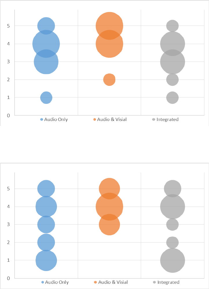
56
Figure 15. “How useful was the warning to you in this situation?” for IMA event
Figure 16. “How distracting was this warning?” for IMA event

57
Figure 17. “Would you pay to have this type of system installed in your vehicle?” for IMA
event
$0
$500
$1,000
$1,500
$2,000
$2,500
$3,000
$3,500
$4,000
$4,500
$5,000
Audio Only Audio & Visual Integrated
Figure 18. “If yes, how much (in dollars)?” for IMA event
4.4 Left Turn Assist Scenario
4.4.1 Specific Method
4.4.1.1 Driving Scenario
The LTA was an urban drive during which participants passed through several traffic light-
controlled intersections with the left turn event at the final intersection with oncoming traffic. At
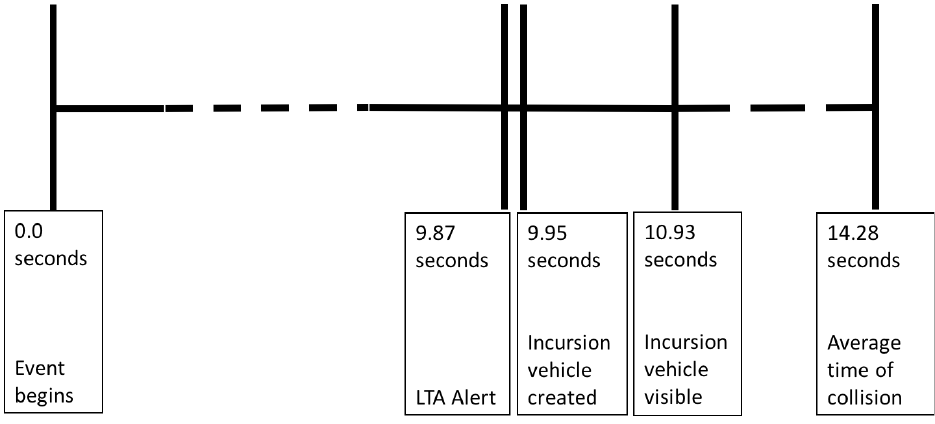
58
intersections prior to the event intersection, cross traffic moved through the intersections as the
driver approached. All traffic signals cycled to green as the driver approached. There was no lead
vehicle in this scenario. The speed limit was set to 35 mph on an urban street, indicated by a
speed limit sign. The driver was prompted to take the next left turn just before the event
intersection. As the driver approached the turn lane, a vehicle turned right on red, coming from
the oncoming lane. The traffic lights cycled at this time, turning to a green left turn signal for the
driver. As the driver crossed the stop bar of the turn lane, the incursion vehicle, hidden by semi-
trucks in the oncoming left turn lane, was created going 50 mph in the oncoming lane. Figure 19.
shows the timing of the LTA event. At the same time, the warning was triggered. The scenario
ended with a prompt after the driver reacted to the incursion vehicle and continued turning
through the intersection and down the road. This scenario lasted 3-4 minutes. Figure 20 provides
a visualization of the driving scene at the point of the LTA warning and Figure 21 provides a
visualization of the driving scene at the point the where the incursion vehicle becomes visible.
Figure 19. Timing of LTA scenario

59
Figure 20. LTA scenario at point when alert is issued

60
Figure 21. LTA scenario at point where incursion vehicle becomes visible
4.4.1.2 Participants
Table 18 provides the distribution of gender and age for the LTA scenario. For the three ASD
DVI warning levels (audio only, audio-visual, and integrated display).
Table 18. Participant gender for each ASD DVI level for the LTA scenario
# of Participants
Mean Age (std. dev.)
Audio Only
12
38.57 (8.88)
Audio-Visual
12
39.30 (8.47)
Integrated Display
12
36.27 (10.14)
Total
36
37.93 (9.36)

61
4.4.2 Results
4.4.2.1 Outcome
Most participants did not experience crashes in the LTA event (Table 19). There were slightly
more crashes for the integrated display.
Table 19. Crashes for each display type in the LTA event
Audio Only
Display
Audio-Visual
Display
Integrated
Display Total
No Collision
11
9
8
28
Collision
1
3
4
8
Total
12
12
12
36
4.4.2.2 Driver Performance
For accelerator pedal release, no significant effect for display type was found (p=0.1946). Since
the p-value is greater than 0.1, no follow up tests were conducted. The lack of significant results
could be due to the low occurrence rate of the accelerator pedal release results (Table 20). The
audio-visual display tended to have a longer accelerator pedal release time than the audio only or
integrated displays (Figure 22).
Table 20. Number of accelerator pedal release responses by display type for LTA event
Number of Responses
Audio Only
6
Audio-Visual
5
Integrated Display
5

62
Figure 22. Accelerator pedal release time from visible for LTA event
No significant effect of display type was found (p=0.6365) for brake application response. Since
the p-value is greater than 0.1, no follow up tests were conducted. The lack of significant results
could be due to the low occurrence rate of the accelerator pedal release results (Table 21). It
should be noted, that participants may have released the accelerator pedal and not followed with
a brake response. The audio-visual display tended to have longer brake response times than the
audio only and integrated displays (Figure 23).
Table 21. Number of brake responses by display type for LTA event
Number of Responses
Audio Only
2
Audio-Visual
4
Integrated Display
2

63
Figure 23. Brake application response time from visible for LTA event
For steering response, no significant effect was found for display type (p=0.5375). No follow-up
tests are reported. The lack of significant results could be due to the low occurrence rate of the
steering response results (Table 22). The audio-visual display tended to have longer steering
response times than the audio only and integrated displays (Figure 24), yet this trend is not as
distinct as was seen for accelerator pedal release and brake response.
Table 22. Number of steering responses by display type for LTA event
Number of Responses
Audio Only
5
Audio-Visual
5
Integrated Display
8

64
Figure 24. Steering response time from visible for LTA event
There were only two accelerator pedal application responses for the LTA event (Table 23); one
in the audio only and one in the integrated display condition, too few for any analysis. The
negative value for accelerator pedal application in the audio only condition indicates that the
accelerator pedal was pressed one second before the incursion vehicle was visible at the time the
alert was issued. In the integrated display condition, the accelerator pedal application was two
seconds after the incursion vehicle became visible. No figure is provided due to the low counts.
Table 23. Number of accelerator pedal application responses by display type for LTA event
Number of Responses
Audio Only
1
Audio-Visual
0
Integrated Display
1
A significant effect for first response was not found (p=0.7090) and follow-up tests were not
conducted. The data do not show a trend. The lack of significant results was due to the
substantial variance in response times, particularly for the audio-visual display rather than the
number of responses (Table 24)

65
Table 24. Number of first responses by display type for LTA event
Number of Responses
Audio Only
8
Audio-Visual
8
Integrated Display
9
Figure 25. First response time from visible for LTA event
4.4.2.3 Subjective Data
Across all three display types, participants reported that they did not know what sort of event the
warning was alerting them to (Figure 26). In fact, only one participant who experienced the
audio-visual display reported “yes.” Also participants reported they could not easily and quickly
interpret the warning (Figure 27) and overall that the warning was not useful (Figure 28). Fewer
participants reported the audio only display to be very distracting (Figure 29) yet the responses
were again fairly evenly distributed. Most participants reported they would not pay for this type
of system to be installed in their vehicle (Figure 30) and, of those who said “yes,” most provided
low dollar amounts.

66
Figure 26. “Did you know what sort of event the warning was trying to alert you to before
you saw the other vehicle?” for LTA event
Figure 27. “How easily and quickly could you interpret this warning?” for LTA event

67
Figure 28. “How useful was the warning to you in this situation?” for LTA event
Figure 29. “How distracting was this warning?” for LTA event

68
Figure 30. “Would you pay to have this type of system installed in your vehicle?” for LTA
event
Figure 31. “If yes, how much (in dollars)?” for LTA event
4.5 EEBL Scenario
4.5.1 Specific Method
4.5.1.1 Driving Scenario
The EEBL scenario began with the participant vehicle parked in the lane of a rural roadway and
an automated audio instructing the participant to shift into drive and begin driving. The speed

69
limit was 55 mph on a rural highway, indicated by a speed limit sign. There was light ambient
traffic in the oncoming lane. There was a lead vehicle and a remote vehicle in this scenario, both
of which turned onto the roadway several seconds into the drive ahead of the driver. The remote
vehicle was ahead of the lead vehicle. The lead vehicle maintained a 2-second gap ahead of the
driver. The remote vehicle maintained a 4-second gap ahead of the driver. The lead and remote
vehicle speeds were bounded between 45-70 mph to allow them to maintain their gaps with the
driver.
As the vehicles approached a controlled access freeway on-ramp, the remote vehicle suddenly
braked to 25 mph at 0.4G, its brake lights concealed by the lead vehicle, then turned onto the on-
ramp (Figure 32). The EEBL warning was triggered 250 ms after the onset of remote vehicle
braking. One second following onset of remote vehicle braking, the lead vehicle braked to 15
mph at 0.7G. Figure 33 shows timing of the EEBL event. The remote vehicle was not visible to
the driver when braking began and the alert was issued. Figure 34 provides a visualization of the
driving scene at the point the EEBL alert. The remote vehicle then made the turn and the lead
vehicle resumed the speed limit. The scenario ended with a prompt after the driver reacted to the
remote vehicle and continued turning through the intersection and down the road. This scenario
lasted 3-4 minutes.
Figure 32. Diagram of EEBL scenario
Figure 33. Timing of EEBL scenario

70
Figure 34. EEBL scenario when alert is issued
4.5.1.2 Participants
Table 25 provides the distribution of gender and age for the EEBL scenario. For the three ASD
DVI warning modes (audio only, audio-visual, and integrated display), the characteristic being
tested is the only condition being tested.
Table 25. Participant gender for each ASD DVI level for the EEBL scenario
# of Participants
Mean Age (std. dev.)
Audio Only
12
38.70 (8.99)
Audio-Visual
12
37.90 (9.57)
Integrated Display
12
37.80 (8.60)
Total
36
38.13 (9.07)

71
4.5.2 Results
4.5.2.1 Outcomes
Most participants were able to avoid a collision in the EEBL event and there was no difference in
collisions across the three display conditions (Table 26).
Table 26. Crashes for each display type in the EEBL event
Audio Only
Display
Audio-Visual
Display
Integrated
Display Total
No Collision
11
11
11
33
Collision
1
1
1
3
Total
12
12
12
36
4.5.2.2 Driver Performance
For accelerator pedal release, no significant effect for display type was found (p=0.0759). Yet
follow-up tests indicated that the audio only display was different than the audio-visual display
(p=0.0288), though not from the integrated display. All 12 participants had a accelerator pedal
release response. There was a trend toward faster responses for the audio-visual and integrated
displays (Figure 35). Since all 12 participants had an accelerator pedal release response, this was
always their first response and further analysis was unnecessary.
Figure 35. Accelerator pedal release time for EEBL event

72
A significant effect was not found for display type (p=0.6730) for brake response. No follow-up
tests were conducted. All 12 participants had a brake response. There was a trend toward faster
responses for the audio-visual display (Figure 36).
Figure 36. Brake response time from visible for EEBL
There were no steering or accelerator pedal application responses for the EEBL event. Also,
since all participants had a accelerator pedal release response that was their first response. No
analysis of steering, accelerator pedal application, or first response was conducted.
4.5.2.3 Subjective Data
Participants who experienced the audio-visual and integrated displays reported that they better
understood the sort of event the warning was alerting them to (Figure 37), yet they reported
similarly positive responses for all display types for how easy and quick the alert was to interpret
(Figure 38) and for the usefulness of the warning (Figure 39). The integrated display was
reported to be more distracting (Figure 40) though the responses for this display were fairly
evenly distributed. Similarly, fewer reported they would pay for the system with the integrated
display to be installed in their vehicle (Figure 41) and, of those who responded “yes,” the highest
amount was for the audio-visual display (Figure 42).

73
Figure 37. “Did you know what sort of event the warning was trying to alert you to before
you saw the other vehicle?” for EEBL event
Figure 38. “How easily and quickly could you interpret this warning?” for EEBL event

74
Figure 39. “How useful was the warning to you in this situation?” for EEBL event
Figure 40. “How distracting was this warning?” for EEBL event

75
Figure 41. “Would you pay to have this type of system installed in your vehicle?” for EEBL
event
$0
$500
$1,000
$1,500
$2,000
$2,500
$3,000
$3,500
$4,000
$4,500
$5,000
Audio Only Audio & Visual Integrated
Figure 42. “If yes, how much (in dollars)?” for EEBL event
4.6 Driving Simulator Study Summary
The primary hypotheses tested in the simulator experiment are provided below as assertive
predictions, rather than as the related “null hypotheses” for inferential statistical testing:
• Driver response time to and type of response to a warning are related to the ASD
interface and onboard information, the CV application, and their interaction.

76
• The benefits of ASD warnings on the event outcome are related to the ASD interface and
onboard information, the CV warning application, and their interaction.
• Driver comprehension of an ASD warning is related to the ASD interface and onboard
information, the CV warning application, and their interaction.
• The perceived benefits and acceptance of an ASD system is related to the ASD interface
and onboard information, the CV warning application, and their interaction.
4.6.1.1 Driver response time to and type of response
Response time varied depending on the ASD interface and CV application. The integrated
display resulted in faster responses in the IMA event than audio only and audio-visual displays.
In the EEBL event there was a trend towards faster responses with the audio-visual and
integrated displays. However, the integrated and audio only displays had faster mean first
response times than the audio-visual display in the LTA event, even though the difference did
not reach statistical significance. These patterns of response time and display type were
consistent within each CV application event type for accelerator pedal release, brake response,
and the first response variables.
Response type also varied with the CV application, yet did not vary across the ASD interface
levels within CV applications. There were essentially the same number of each type of response,
regardless of whether or not the display contained information about the direction of the threat.
In the IMA and EEBL events, most participants had both accelerator pedal release and brake
application responses. Significantly fewer had steering or accelerator pedal application responses
in the IMA event and none had either of these responses in the EEBL event. A different pattern
was seen in the LTA event where approximately half the participants had accelerator pedal
release and/or steering responses, yet very few had either brake or accelerator pedal application
responses. Response type was dependent on the collision situation rather than the ASD display.
One possible explanation for differences in response type is whether the driver is actively
engaged in a maneuver (steering, acceleration or deceleration) at the time of alert. Steering
responses were certainly valid response types for both the IMA and EEBL events, yet very few
or none occurred in these events. In the LTA event where drivers were already engaged in a
maneuver, the response type varied and no one response type dominated.
There were no instances of alert suppression in this study as a result of availability of CAN bus
data. This result does not necessarily mean that ASD access to the vehicle’s CAN bus data has
no benefit. Other real-world driving scenarios may be more likely to allow alert suppression
when the driver is already responding to the potential collision situation. Yet, what was not
considered in this study was prioritization of alerts. If there are OEM warning systems and
aftermarket warning systems in the same vehicle, without integration of onboard data there is no
opportunity to prioritize alerts from various systems that could result in multiple alerts issued
simultaneously or in close temporal proximity. Additionally, the potential utility of alert
suppression in untested CV applications, such as Lane Departure or Blind Spot Warning, is
unclear. Importantly, this experiment was not able to investigate the effects of response
suppression strategies over repeated experience with the system. More precisely adapted alerting
algorithms may improve warning validity and timing, which ultimately may improve the speed
and appropriateness of driver response as well as user acceptance and system use. Such benefits
can only be assessed through longer term exposure to alternative systems.

77
Overall, based on driver response across all three CV applications, the integrated display
performed better than the audio only and audio-visual displays suggesting that ASD DVIs may
be less effective than OEM installed systems. Further, these results support the application to
EEBL systems of the SAE and HFCV guidance (SAE, 2003; Campbell et al., 2007) for FCW
systems recommending audio and visual components.
The driving simulator study provided a comparison among three prototype ASD concepts, with a
focus on how systems without vehicle integration compare with highly integrated or OEM
systems. The experiment did not provide any direct comparison of these systems with a “no
warning” system. However, some inference can be made based on the absolute values of the
response times. In some instances, response times are shorter than reasonably would be expected
in reaction to a visible, unanticipated event. Figure 12 showed “first response” latency for the
IMA event from the onset of the conflicting vehicle becoming visible. Although the Level 3
(integrated) system had the briefest response time, the response time for the Level 2 (audio-
visual) system were typically in the 0.50 to 0.75 second range. For the LTA event, mean
accelerator pedal release time for the Level 1 (audio only) system was at nearly the same
moment as the conflicting vehicle became visible (Figure 22). For the EEBL event, mean
accelerator pedal release time was less than 1 second for Level 1 and only about a quarter second
for Level 2. While not definitive, the occurrence of driving responses so shortly after the
appearance of a conflicting vehicle suggests that many participants initiated an action in response
to the preceding alert or were primed to respond quickly because of the alert. Thus even lower
capability systems may offer safety benefits relative to no warning under some conditions.
4.6.1.2 Event outcome
Outcomes were more heavily influenced by CV warning application event than by the ASD
display level, yet there were some important differences. In the IMA event, most participants
experienced crashes. In the LTA and EEBL events, most participants were able to avoid crashes.
All three events were designed to have similar and consistent timing (1 second from alert to
incursion vehicle visible, then 3 seconds from visible to collision), though actual timing was
influenced by driver speed and response. Due to variations in driver speed, the IMA event had a
slightly lower visible-to-collision time (2.48 seconds) and it would be tempting to suggest that
this shorter visible-to-collision time is the reason for the higher rate of collisions in the IMA
event, yet this is not supported by the timing of the LTA and EEBL events. The EEBL event had
a visible-to-collision time of 3.08 seconds and the fewest crashes, while the LTA had a longer
visible-to-collision time of 3.35 seconds and more crashes than EEBL, though fewer than IMA.
Table 27. Total number of collisions for each event and interface
Event
Audio Only Display
Audio-Visual Display
Integrated Display
IMA
12
11
9
LTA
1
3
4
EEBL
1
1
1
Total
14
15
14
78
Two significant differences between the three types of events were the uncertainty of the
direction of the collision threat and whether or not the driver was in the process of completing a
maneuver. In the EEBL event, the direction of threat was clearly a rear-end collision with the
vehicle ahead and no maneuver in progress. In the IMA and LTA events, the drivers were
passing through an intersection and the direction of threat could be from either side in the IMA
event and any of three directions (left, right, or oncoming) in the LTA event. Only in the LTA
event was a maneuver in progress. This may suggest that direction of the threat and whether or
not a maneuver is in progress should be considered in the design of warning displays.
Recall that the audio only display included no directional information, the audio-visual included
the same audio alert and a visual icon with threat direction displayed in a box on the dash of the
vehicle, and the integrated display included the same audio alert and indicated the direction of
threat by illuminating light strips to indicate direction of threat (left = left A-pillar and left front
strips, forward = the two front strips, right = right front and right A-pillar strips). The effect on
outcome for the three levels of ASD display was mixed across the three types of events studied.
With the integrated display, there were fewer crashes in the IMA event and more crashes in the
LTA event than the audio only or audio-visual displays, and no difference in the EEBL event.
No difference between the ASD display levels for the EEBL event suggests that there is neither a
benefit nor dis-benefit to threat direction information when the direction of threat is clear and no
maneuver is in progress. Fewer crashes with the integrated display in the IMA suggest that ASD
systems with add-on displays may be less effective at preventing crashes than fully-integrated
systems or OEM installed systems when the driver is not in the process of completing a
maneuver. Yet, when drivers were in the process of completing a maneuver and direction of
threat was relative to the driver’s progress through that maneuver (LTA), there was a dis-benefit
associated with the inclusion of directional information.
4.6.1.3 Driver comprehension
Drivers rated their comprehension of the alert differently across the three ASD application
events. For the IMA and LTA events, most drivers indicated they did not know to what the
warning was alerting them. The comprehension was higher for the EEBL event, particularly for
the audio-visual and integrated displays where 50% and 75%, respectively, reported they did
understand the sort of event to which the warning was alerting them. These patterns mirror
drivers’ responses to how easily and quickly they could interpret the warning. These findings are
consistent with driver response and event outcome results.
4.6.1.4 Perceived benefits and acceptance
For the IMA event, none of the ASD interfaces were rated as useful and all participants rated the
audio-visual display as distracting, while the responses were fairly evenly distributed for the
audio only and integrated displays. More participants said they would pay for the audio-visual
and integrated display and reported higher amounts they would pay for such a system, which is
consistent with the driver response and outcome results.
For the LTA event, participants did not rate any of the displays as useful and the distraction
ratings were evenly distributed. Fewer than 25 percent of participants indicated they would pay
for the CV system and values tended to be less than $500.
For the EEBL event, participants rated all three ASD interfaces as useful, and they rated the
audio only and audio-visual interfaces as less distracting than the integrated display. Similarly,
79
more than half the participants responded that they would pay for an audio only or audio-visual
system and slightly fewer than half said the same about a system in an integrated display.
80
5. General Discussion and Limitations
5.1 General Discussion
This project investigated human factors issues related to the DVI for ASDs providing CV safety
alerts to drivers. The project activities included literature reviews, product search, interviews
with industry experts, analytic assessments, and a simulator experiment of warning responses.
There is not strong consensus among industry experts and other sources regarding the likely form
of ASDs and particularly regarding the needs for interfacing with the host vehicle’s safety and
communications systems. Some believe that ASDs will not be acceptable without a strong degree
of integration with vehicle systems, for reasons related to system performance, suppression of
inappropriate warnings, redundant or conflicting messages, message prioritization, and
installation requirements (including appropriate antenna type and location). Others feel that
stand-alone ASDs may nonetheless provide valuable safety benefits, even if they are not as
capable as a fully integrated or OEM product. Less complex ASDs systems may be lower cost
and easier to install, which may allow the benefits to be shared by a broader and more equitable
range of drivers, including those with older or less expensive vehicles. Ultimately, the potential
public safety benefits of ASDs are twofold. First, they provide potential safety benefits to the
individual driver in the form of CV alerts. Second, they foster greater fleet penetration of here-I-
am basic CV information, which enhances the effectiveness of the CV technology for all
vehicles. Both of these aspects are important considerations for ASDs but industry expert
consensus on the prospects and requirements is lacking. There are trade-off considerations
between more sophisticated and precise warning and display capabilities and prospects for
aftermarket consumer motivation.
There is very little direct research on CV ASDs and little in the way of existing products as
exemplars. Thus, there are not clear prototype systems as a basis for research. Suppliers of CV
systems generally provide their products to OEMs without a DVI or with DVI specifications
provided by the OEM. OEM interfaces are proprietary. There has not been much attention given
to aftermarket DVIs. The Safety Pilot Model Deployment (e.g., Bezzina & Sayer, 2015)
provided drivers with actual CV warning systems. However, none of the ASDs included DVI
elements other than an auditory tone. This represents a minimal DVI for an ASD and serves as a
lower-end system for comparison with other interface concepts for research conducted under this
project.
OEM CV systems will be able to make use of various onboard vehicle information to use in
conjunction with CV information. This should allow more refined warning algorithms that may
take into account vehicle state, roadway and environment factors, driver state, driver intent, and
information on external objects and events (e.g., obstacles, pedestrians, vehicles) from onboard
sensors. Onboard information has the potential both to optimize the timing and nature of
particular warnings and also to suppress unnecessary warnings. Over driver experience with the
system, this may influence user perceptions of warning validity and system acceptability. To the
extent that OEMs effectively use such information, ASDs that are not highly integrated with the
host vehicle may suffer in terms of relative performance. Relative to such potential OEM
systems, ASDs may have more slow or missed driver responses, less system use or more system
defeat, and less consumer willingness to inquire or install a CV product. Because many of the
potential effects of system access to onboard data will only emerge over time and experience,
81
research studies on this aspect are difficult and extended. Potential influences of key onboard
data sources were addressed analytically in this project. It is noted that it may be possible for
ASDs to collect and utilize similar information from other sources and sensors that may be part
of the ASD product, but this would of course influence cost.
Fleet penetration of ASD systems will depend on consumer interest in the product. The literature
indicates that consumers do not appear to be willing to pay much for CV technologies (e.g., Shin,
Callow, Dadvar, & Farkas, 2015), a finding supported by observations in the driving simulator
study conducted in this project. However, consumer experience and familiarity with the
technology is very limited and opinion could change as public knowledge expands and as new
vehicles come equipped with CV technology. Observations from the Safety Pilot Model
Deployment (Bezzina & Sayer, 2015) suggest that nuisance alarm rates may be an important
factor in public acceptance. Other factors raised that may improve consumer interest in ASDs
include packaging the CV component with other non-safety applications (e.g., parking
assistance, insurance discounts), portability, and customizability.
This research project included a driving simulator study that had a primary focus on the speed
and appropriateness of vehicle control actions in avoiding a crash. This study compared three
prototype ASD DVIs. One system (Level 1) simulated a stand-alone product that only provides a
tonal alert. Another system (Level 2) was also stand-alone, but added a visual display on the
product that depicts a crash threat and its direction. The final system (Level 3) simulated a highly
integrated or OEM system. The acoustic component was directional and the visual alert was by
light bars in the vehicle cabin that illuminate from the direction consistent with the threat. Three
different CV applications were included: Intersection Movement Assist (IMA), Left Turn Assist
(LTA), and Emergency Electronic Brake Lights (EEBL).
The driving simulator experiment found that the relative performance of the three systems
depended on the particular driving scenario. Broadly speaking, the Level 3 system tended to
result in somewhat faster responding (e.g., pedal release, brake activation, steering input) and
fewer crashes to the threat event, although this was not a uniform finding and was not always
statistically significant (sample size and response variability limit the ability to provide
statistically significant findings). The driving simulator experiment did not include a direct
comparison of responding with a “no warning” condition due to scope considerations to be able
to include alert suppression conditions. However, a consideration of the absolute response times,
based on the moment the threat vehicle became visible, suggests that even the Level 1 and 2
systems may provide some benefit in terms of faster driver response.
Based on the findings of this experiment, there appear to be benefits to an integrated DVI for
ASDs, in terms of response speed and appropriateness, comprehension, and acceptance. Less
clear are the benefits of lower level DVIs relative to no warning, although there is a suggestion
that performance is better than in the absence of any warning.
5.2 Study Limitations
The findings of this study must be considered within the context of its limitations. ASDs are still
in the early stages of development and there is no clear consensus or trend to indicate the types
of ASDs that are likely to come to market. Experts and developers do not even agree on
fundamental points, such as whether access to onboard vehicle CAN bus data and professional
installation is necessary to make a viable CV ASD. The three ASD prototypes used in this study
82
were designed to represent the range of device types and interfaces currently in development, or
likely to be used, while also providing distinct differences between systems. They are, however,
not the only possible approaches to ASD warnings.
This experiment also used a limited number of carefully scripted event scenarios and drivers who
were attentive during their drives. Additionally, because this study used a between-subject design
no comparison of different ASD DVIs for the same driver was possible. Effects of driver
distraction and a broader range of collision scenarios were not investigated. Similarly, these
experiments did not include naturalistic, longitudinal exposure to ASDs. Longer-term use of
ASDs under normal driving conditions is important to understand driver attitudes toward these
systems, and especially to investigate the effects of CAN bus data access on warning adaptation
and suppression, and in turn, driver trust and acceptance of the system. Finally, the simulator
experiment investigated differences between the three ASD levels, but did not include a no-ASD
comparison condition.
83
References
Bezzina, D., & Sayer, J. (2015). Safety Pilot Model Deployment: Test Conductor Team Report.
Report no. DOT HS 812 171. Washington, DC: National Highway Traffic Safety
Administration.
Bishop, R. (2012). Evolution of Vehicle Connectivity Industry-wide. Presented at Naturalistic
Driving Research Symposium. Blacksburg, VA.
Campbell, J. L., Richard, C. M., Brown, J. L., & McCallum, M. (2007). Crash warning system
interfaces: human factors insights and lessons learned. Final Report DOT HS 810, 697.
Washington, DC: National Highway Traffic Safety Administration.
Chan, C.-Y. (2012). Enabling Accelerated Installation of Aftermarket Onboard Equipment for
Connected Vehicles. Prepared by Industrial Technology Research Institute California
PATH UC Berkley and Visteon Corporation for University of Virginia Cooperative
Transportation System Pooled Fund Study.
Cohda Wireless. (2015). MK5 V2X On Board Unit [Data sheet]. Retrieved May, 2017 from
http://cohdawireless.com/Portals/0/MK5_OBU_10122015.pdf
Doerzaph, Z., Sullivan, J., Bowman, D., & Angell, L. (2013). Connected vehicle integration
research and design guidelines development: Integration architecture, Task 5 (Report
under Contract No. DTNH22-11-D-00236/0001). Washington, DC: National Highway
Traffic Safety Administration.
Driver Focus-Telematics Working Group. (2006). Statement of Principles, Criteria and
Verification Procedures on Driver Interactions with Advanced In-Vehicle Information
and Communication Systems, Version 2.0: Alliance of Automotive Manufacturers
(AAM).
Fitch, G.M., Bowman, D. S., & Llaneras, R.E. (2014). Distracted driver performance to multiple
alerts in a multiple-conflict scenario. Human Factors, 56(8), 1497-1505.
Forkenbrock, G.J., Snyder, A.A., O’Harra, B.C., Hoover, R.L., Vasko, S.M., & Smith, L.A.
(2011). A test track protocol for assessing forward collision warning driver-vehicle
interface effectiveness. Washington, DC: National Highway Traffic Safety
Administration.
Gilbert, M. (2012). Aftermarket safety device installation procedure for Safety Pilot Model
Deployment. Prepared by University of Michigan Transportation Research Institute and
Partner Organizations. Unpublished.
Harding, J., Powell, G., R., Yoon, R., Fikentscher, J., Doyle, C., Sade, D., Lukuc, M., Simons, J.,
& Wang, J. (2014). Vehicle-to-Vehicle Communications: Readiness of V2V Technology
for Application. Report no. DOT HS 812 014. Washington, DC: National Highway
Traffic Safety Administration.
Holmes, L., Harwood, L., Klauer, S., Doerzaph, Z. (2014) Connected Vehicle Systems:
Evaluation of Display Location and Application Type on Driving Performance.
Transportation Research Record: Journal of the Transportation Research Board, Volume
2424.
84
Jenness, J.W., Baldwin, C., Chrysler, S., Lee, J.D., Manser, M., Cooper, J., Salvucci, D.,
Benedick, A., Huey, R., Robinson, E., Gonzales, C., Lewis, B., Eisert, J., Marshall, D.,
Lee, J., Morris, N, & Becic, E. (in press). Connected Vehicle DVI Design Research and
Distraction Assessment. Washington, DC: National Highway Traffic Safety
Administration.
Lerner, N., Jenness, J., Robinson, E., Brown, T., Baldwin, C., & Llaneras, R. (2011). Crash
warning interface metrics: Final report. (DOT HS 811 470a). Washington, DC: National
Highway Traffic Safety Administration.
Lerner, N., Robinson, E., Singer, J., Jenness, J., Huey, R., Baldwin, C., & Fitch, G. (2014,
September). Human factors for connected vehicles: Effective warning interface research
findings. (Report No. DOT HS 812 068). Washington, DC: National Highway Traffic
Safety Administration.
Levi, S., Yahoodik, S., Singer, J., Lerner, N., & Marshall, D. (2016). Aftermarket Safety Device
Driver Vehicle Interface Guidance Development: Draft Literature Review and Gap
Analysis. Unpublished interim project report under Contract # DTNH22-11-D-
00237L/0015
Lewis, B. A., Eisert, J. L., Baldwin, C. L., Singer, J., & Lerner, N. (2017, March). Urgency
coding validations (Final report. Report No. DOT HS 812 385). Washington, DC:
National Highway Traffic Safety Administration
National Highway Traffic Safety Administration (2013). Visual-Manual NHTSA Driver
Distraction Guidelines for In-Vehicle Electronic Devices. Docket No. NHTSA-2010-
0053. Washington, DC: National Highway Traffic Safety Administration.
SAE. (2003). Human Factors in Forward Collision Warning Systems: Operating Characteristics
and User Interface Requirements (Vol. SAE J2400).
Shin, H., Callow, M., Dadvar, S., Lee, Y., & Farkas, Z. (2015). Measuring User Preference and
Willingness-to-pay for Connected Vehicle Technologies: The Analysis of the Adaptive
Choice-Based Conjoint Survey. Presented at Transportation Research Board Annual
Meeting, Washington, D.C.
University of Iowa (2015) Summary of Responses to Informal Calls with Potential Installers of
Aftermarket Systems, Unpublished interim project deliverable under Contract #
DTNH22-11-D-00237L/0015.

A-1
Appendix A: Simulator Experiment Phone Screening

A-2

A-3

A-4

A-5

A-6

A-7

B-1
Appendix B: Simulator Experiment Informed Consent

B-2

B-3

B-4

B-5

C-1
Appendix C: Simulator Experiment Demographic and Driving
Questionnaire

C-2

C-3

C-4

C-5

D-1
Appendix D: Simulator Experiment Post Drive Questionnaire

E-1
Appendix E: Simulator Experiment Wellness Survey

F-1
Appendix F: Simulator Experiment Realism Survey

F-2

G-1
Appendix G: Simulator Experiment Debriefing Statement

DOT HS 812 513
December 2018
13571-121418-v4
