
Department of Chemical Engineering, Veer Surendra Sai University of Technology Burla
1
PROCESS CONTROL LAB
LAB MANUAL
For Temperature Control Trainer
List of Experiments:-
1. To study Tuning of controller (Using Auto Tuning method)
2. Study of open loop response (Manual control)
3. Study of on/off controller
4. Study of proportional controller
5. Study of proportional integral controller
6. Study of proportional derivative controller
7. Tuning of controller (Open loop method)
8. Tuning of controller (Closed loop method)
9. To study Tuning of controller (Using Auto Tuning method)
10. Study of stability of the system (Bode plot)
For Pressure Control Trainer
List of experiments:-
1. To study of open loop response (manual control)
2. To study of on/off controller.
3. To study of proportional controller
4. To study of proportional integral controller
5. To study of proportional derivative controller
6. To study of proportional integral derivative controller
7. To tuning of controller (open loop method)
8. To tuning of controller (closed loop method)
9. To tuning of controller (using auto tuning method)
10. To study stability of the system (Bode plot)
For Level Control Trainer
List of experiments:-
1. To study of open loop response (manual control)
2. To study of on/off controller.
3. To study of proportional controller
4. To study of proportional integral controller
5. To study of proportional derivative controller
6. To study of proportional integral derivative controller
7. To tuning of controller (open loop method)
8. To tuning of controller (closed loop method)
9. To tuning of controller (using auto tuning method)
10. To study stability of the system (Bode plot)

Department of Chemical Engineering, Veer Surendra Sai University of Technology Burla
2
Temperature Control Trainer
1. Aim of the experiment:-
Study of open loop response (Manual control)
Apparatus required:-
Temperature Control Trainer
Theory: - :- Temperature control trainer is designed for
understanding the basic temperature control
principles. The process setup consists of heating tank fitted with SSR controlled heater for on-line
heating of the water. The flow of water can be manipulated and measured by
rotameter.
Temperature sensor (RTD) is used
for temperature sensing. The process parameter (Temperature) is
controlled by microprocessor based digital indicating controller which manipulates heat input to
the process. These units along with necessary
piping and fitting are mounted on support frame
designed for tabletop mounting.
Procedure
Start up set up as explained in general instructions.
Click Select Experiment, select Open Loop and click Start
Decrease the controller output to 0%. Note down steady state process value.
Apply the step change by 10% to controller output and wait for the temperature to reach
Solid State Relay
Electric Supply
Set Point
Rotameter
Temperature
Controller
Temperature Sensor
Water Supply
Heater Heating Tank
Drain

Department of Chemical Engineering, Veer Surendra Sai University of Technology Burla
3
the steady state value. Note down the process value.
Repeat the above step until the controller output reaches to maximum i.e. 100% and for
each change, note steady state process value.
Observations
Tabulate the observations as follows
Controller output in %
Process Value in
0
C
0
10
20
…
100
From the above data, note the output required for maintaining the temperature at desired
set points.
2. AIM OF THE EXPERIMENT:-
Study of on/off controller
Apparatus required:-
Temperature Control Trainer
THEORY: - :- Temperature control trainer is designed for
understanding the basic temperature
control
principles. The process setup consists of heating tank fitted with SSR controlled heater for
on-line heating of the water. The flow of water can be manipulated and measured by
rotameter.
Temperature sensor (RTD) is used
for temperature sensing. The process parameter (Temperature) is
controlled by microprocessor based digital indicating controller which manipulates heat input to
the process. These units along with necessary
piping and fitting are mounted on support frame
designed for tabletop mounting.

Department of Chemical Engineering, Veer Surendra Sai University of Technology Burla
4
Procedure:-
Start up set up as explained in general instructions.
Click Select Experiment, select On-Off Mode and click Start
Change Hysteresis value to 1 %.( Range 0.1-10%)
Change the values of the set point and observe the On-Off control operation.
Solid State Relay
Electric Supply
Set Point
Rotameter
Temperature
Controller
Temperature Sensor
Water Supply
Heater Heating Tank
Drain
Department of Chemical Engineering, Veer Surendra Sai University of Technology Burla
5
Observations
Observe that if process value exceeds the set point and increases than the value of (0.5x
Hysteresis), controller switches off the SSR and if process value decreases below the set point by
(0.5 x Hysteresis), SSR switches on i.e. controller operates like On/Off switch.

Department of Chemical Engineering, Veer Surendra Sai University of Technology Burla
6
3. Aim of the experiment:-
Study of proportional controller
Apparatus required:-
Temp. Control trainer
Theory: - Temperature control trainer is designed for
understanding the basic temperature control
principles. The process setup consists of heating tank fitted with SSR controlled heater for on-line
heating of the water. The flow of water can be manipulated and measured by
rotameter.
Temperature sensor (RTD) is used
for temperature sensing. The process parameter (Temperature) is
controlled by microprocessor based digital indicating controller which manipulates heat input to
the process. These units along with necessary
piping and fitting are mounted on support frame
designed for tabletop mounting.
Procedure
Start up set up as explained in general instructions.
Click Select Experiment, select P Mode and click Start
Keep the set point to 40%. (Set point should be 10% more than inlet water temperature)
Change output mode to Manual. Adjust output value so as to match the process value with
set point and apply this output value as bias value to the controller. Adjust the proportional
band to 50%.
Switch the controller to Auto mode.
Apply step change to set point, step change should be of 2 to 3 % and observe the response.
Solid State Relay
Electric Supply
Set Point
Rotameter
Temperature
Controller
Temperature Sensor
Water Supply
Heater Heating Tank
Drain

Department of Chemical Engineering, Veer Surendra Sai University of Technology Burla
7
Switch the controller to Manual mode. Decrease proportional band to half of the previous
value & then shift controller to Auto mode. With each decrease, obtain a new response of
the step change. Ensure that the set point changes are around the same operating point (@
2-
3% only).
Using trial and error approach, find a value of proportional band so that the response to a
step change has at most one overshoot and one undershoot.
Set the controller to the settings obtained in the above step and wait for the system to
reach at
steady state.
Observations
Observe steady state error decreases as proportional band decreases.
Observe the effect of very low proportional band values (system works in oscillatory mode).
Observe the response of the system to load change. Load change can be given by slightly
varying the inlet flow rate.

Department of Chemical Engineering, Veer Surendra Sai University of Technology Burla
8
4. Aim of the experiment:
To Study of proportional integral controller
Apparatus required:-
Temp control trainer
Theory: - Temperature control trainer is designed for
understanding the basic temperature control
principles. The process setup consists of heating tank fitted with SSR controlled heater for on-line
heating of the water. The flow of water can be manipulated and measured by
rotameter.
Temperature sensor (RTD) is used
for temperature sensing. The process parameter (Temperature) is
controlled by microprocessor based digital indicating controller which manipulates heat input to
the process. These units along with necessary
piping and fitting are mounted on support frame
designed for tabletop mounting.
Procedure
Start up set up as explained in general instructions.
Click Select Experiment, select PI Mode and click Start
Adjust the process value by changing the output of controller in manual mode to a particular
temperature (set point =40%).
Set the proportional band estimated from Proportional control (from previous experiment).
Start with derivative time=0 and integral time=1000 sec., which will cut off the derivative
action and widen the effect of integral action.
Allow the process to reach at steady state. Record the steady state error.
Solid State Relay
Electric Supply
Set Point
Rotameter
Temperature
Controller
Temperature Sensor
Water Supply
Heater Heating Tank
Drain

Department of Chemical Engineering, Veer Surendra Sai University of Technology Burla
9
Switch on the controller to manual mode. Reduce the integral time to half of the previous
value. Switch to Auto mode and apply step change to the set point by 2 to 3%. Note the
response of the system.
Using trial and error, find out an integral time, which gives satisfactory response to the step
change in set point.
Observations
Observe the effect of reducing integral time on offset and on the response of the process.

Department of Chemical Engineering, Veer Surendra Sai University of Technology Burla
10
5. Aim of the experiment:-
To Study of proportional derivative controller
Apparatus required:-
Temp control trainer
Theory: - Temperature control trainer is designed for
understanding the basic temperature control
principles. The process setup consists of heating tank fitted with SSR controlled heater for on-line
heating of the water. The flow of water can be manipulated and measured by
rotameter.
Temperature sensor (RTD) is used
for temperature sensing. The process parameter (Temperature) is
controlled by microprocessor based digital indicating controller which manipulates heat input to
the process. These units along with necessary
piping and fitting are mounted on support frame
designed for tabletop mounting.
Procedure
Start up set up as explained in general instructions.
Click Select Experiment, select PD Mode and click Start
Set the proportional band estimated from Proportional control (P only). Start with derivative
time=0 and integral time=6000 sec., which will cut off the derivative action and widen the
effect of integral action.
Set the set point to desired temperature (@40%). Allow the process to reach at steady state.
Solid State Relay
Electric Supply
Set Point
Rotameter
Temperature
Controller
Temperature Sensor
Water Supply
Heater Heating Tank
Drain

Department of Chemical Engineering, Veer Surendra Sai University of Technology Burla
11
Note the response of the system.
Switch on the controller to manual mode. Increase the derivative time by 1 sec. Switch to
Auto mode and apply step change to the set point by 2 to 3%. Note the response of the
system.
Increase the derivative time gradually and observe the process response for step change.
Observations
Observe the effect of increasing derivative time. Also note that the process may show offset
as effect of integral action is cut off.

Department of Chemical Engineering, Veer Surendra Sai University of Technology Burla
12
6. Aim of the experiment:-
To Study of proportional integral derivative controller
Apparatus required:-
Temperature control trainer
Theory: - Temperature control trainer is designed for
understanding the basic temperature control
principles. The process setup consists of heating tank fitted with SSR controlled heater for on-line
heating of the water. The flow of water can be manipulated and measured by
rotameter.
Temperature sensor (RTD) is used
for temperature sensing. The process parameter (Temperature) is
controlled by microprocessor based digital indicating controller which manipulates heat input to
the process. These units along with necessary
piping and fitting are mounted on support frame
designed for tabletop mounting.
Solid State Relay
Electric Supply
Set Point
Rotameter
Temperature
Controller
Temperature Sensor
Water Supply
Heater Heating Tank
Drain

Department of Chemical Engineering, Veer Surendra Sai University of Technology Burla
13
Procedure
Start up set up as explained in general instructions.
Click Select Experiment, select PID mode and click Start
Switch the controller to manual mode.
Change the proportional band to the value that estimated in proportional controller. Set
integral time and derivative time based on the responses in previous experiments.
Change the controller to Auto mode. Apply step change by 2 to 3% to the set point and
observe the response of the process.
Change the proportional band, integral time, derivative time and observe the response of
the process for step change for each change in setting.
Observations
Compare the steady state response of the PID controller with P, PI and PD controller
obtained in the previous experiments.

Department of Chemical Engineering, Veer Surendra Sai University of Technology Burla
14
7. Aim of the experiment:-
To study Tuning of controller (Open loop method)
Apparatus required:-
Temp.control trainer
Theory: - Temperature control trainer is designed for
understanding the basic temperature control
principles. The process setup consists of heating tank fitted with SSR controlled heater for on-line
heating of the water. The flow of water can be manipulated and measured by
rotameter.
Temperature sensor (RTD) is used
for temperature sensing. The process parameter (Temperature) is
controlled by microprocessor based digital indicating controller which manipulates heat input to
the process. These units along with necessary
piping and fitting are mounted on support frame
designed for tabletop mounting.
Solid State Relay
Electric Supply
Set Point
Rotameter
Temperature
Controller
Temperature Sensor
Water Supply
Heater Heating Tank
Drain

Department of Chemical Engineering, Veer Surendra Sai University of Technology Burla
15
Procedure
Start up set up as explained in general instructions.
Click Select Experiment, select Process Reaction and click Start
Adjust the controller output and bring the process near set point of 40%.
Allow the system to reach steady state. Start data logging.
With the controller still in manual mode impose a step change of 30 - 40 % in
controller output. Record the step response. Wait for the steady state. Stop data
logging.
Plot the step response (Process reaction curve) from stored data. Find out the value of slope
at
the point of inflection and time lag.
Calculate P I D settings for different modes.
Select PID Mode option for control from software. (Click on “Change Expt.” Button, click
on
“Change”, Click on “PID Mode” button.) Switch on the controller to manual mode and
Keep
the set point to 40%. Adjust output value so as to match the process value to set
point.
Set the PID values obtained from the calculations. Switch on the controller to Auto mode.
Apply the step change & observe the response of the system. Allow the system to reach
steady state.
Observations
(Refer Theory process control for formula.)
Step change to the system P = Initial output- Final output of the controller.
Plot the graph of process value Vs Time on a graph paper.
From process reaction curve:
o Slope of the process reaction curve R =
o Time lag L=
Calculate P, PI, and PID setting from above values.
Observe response of the system for different PID settings.

17-04-2017
16
Im314A
Department of Chemical Engineering, Veer Surendra Sai University of Technology Burla
8. Aim of the experiment:-
To study Tuning of controller (Closed loop method)
Apparatus required:-
Temp. Control trainer
Theory: - Temperature control trainer is designed for
understanding the basic temperature control
principles. The process setup consists of heating tank fitted with SSR controlled heater for on-line
heating of the water. The flow of water can be manipulated and measured by
rotameter.
Temperature sensor (RTD) is used
for temperature sensing. The process parameter (Temperature) is
controlled by microprocessor based digital indicating controller which manipulates heat input to
the process. These units along with necessary
piping and fitting are mounted on support frame
designed for tabletop mounting.
Procedure
Start up set up as explained in general instructions.
Click Select Experiment, select Close Loop and click Start
Set the proportional band value to maximum (Say 100). Set the controller to manual mode
and adjust the output so that the process is nearly at set point 40%.
Set controller to auto mode and impose step on the process by moving the set point for a
few seconds & then return to its original value (or apply the step change to the set point of
2%). Wait for some time & observe the response.
Solid State Relay
Electric Supply
Set Point
Rotameter
Temperature
Controller
Temperature Sensor
Water Supply
Heater Heating Tank
Drain

17-04-2017
17
Im314A
Department of Chemical Engineering, Veer Surendra Sai University of Technology Burla
Decrease the proportional band to the half of previous and impose step on the process as
mentioned above. Wait for some time & observe the response.
Repeat the above procedure and find out correct value of proportional band for which the
system just goes unstable i.e. continuous oscillations are observed in the output of
controller.
Record the ultimate proportional band and ultimate period from the response.
Calculate the PID values from the table. Select the PID controller and apply the parameter
values obtained from the above steps. Observe the response of the process to a step change
with these settings.
Observations
Record the ultimate proportional band (Pbu) and ultimate period (Tu) from above
experiment.
Calculate PID values by referring theory part for different control actions.
Observe the process response for these settings.
Compare the values obtained with open loop response me

17-04-2017
18
Im314A
Department of Chemical Engineering, Veer Surendra Sai University of Technology Burla
9. Aim of the experiment:-
To study Tuning of controller (Using Auto Tuning method)
Apparatus required:-
Temperature control trainer
Theory: - Temperature control trainer is designed for
understanding the basic temperature control
principles. The process setup consists of heating tank fitted with SSR controlled heater for on-line
heating of the water. The flow of water can be manipulated and measured by
rotameter.
Temperature sensor (RTD) is used
for temperature sensing. The process parameter (Temperature) is
controlled by microprocessor based digital indicating controller which manipulates heat input to
the process. These units along with necessary
piping and fitting are mounted on support frame
designed for tabletop mounting.
The controller can be connected to computer through Ethernet
/
USB port for monitoring
the process in SCADA mode.
Solid State Relay
Electric Supply
Set Point
Rotameter
Temperature
Controller
Temperature Sensor
Water Supply
Heater Heating Tank
Drain

17-04-2017
19
Im314A
Department of Chemical Engineering, Veer Surendra Sai University of Technology Burla
Procedure:-
Start up set up as explained in general instructions.
Click Select Experiment, select Autotune and click Start
Wait Till Auto tune is complete. (Blinking of green LED stops).
Controller automatically finds the PB, IT & DT values.
Find out PID values at different set points /flow rates.
Observations
The controller has preprogrammed logic for finding “Auto tune” values. Based on the
response of the process the controller calculates PID values or comes out without finding the
“Auto tune” values.

17-04-2017
20
Im314A
Department of Chemical Engineering, Veer Surendra Sai University of Technology Burla
10. Aim of the experiment:-
Study of stability of the system (Bode plot)
Apparatus required:-
Temp control trainer
Theory: - Temperature control trainer is designed for
understanding the basic temperature control
principles. The process setup consists of heating tank fitted with SSR controlled heater for on-line
heating of the water. The flow of water can be manipulated and measured by
rotameter.
Temperature sensor (RTD) is used
for temperature sensing. The process parameter (Temperature) is
controlled by microprocessor based digital indicating controller which manipulates heat input to
the process. These units along with necessary
piping and fitting are mounted on support frame
designed for tabletop mounting.
The controller can be connected to computer through Ethernet
/
USB port for monitoring
the process in SCADA mode.
Procedure
Start up set up as explained in general instructions.
Click Select Experiment, select Stability analysis and click Start
Solid State Relay
Electric Supply
Set
Point
Rota meter
Temperature
Controller
Temperature Sensor
Water Supply
Heater Heating Tank
Drain

17-04-2017
21
Im314A
Department of Chemical Engineering, Veer Surendra Sai University of Technology Burla
Select function generator to apply the sinusoidal input to the output of the controller.
Enter Reference point, Amplitude and Period.
Observe the sinusoidal output of the controller and sinusoidal response of the process.
Log the data for records.
Change the period and repeat the observation for 3-4 different values of the period.
Note
: As the temperature process is very slow responsive, the amplitude and period for the
sinusoidal input should be large enough to observe response.
Observations
Form the data file stored note down the
Observe the output response of the process and note down the output amplitude. Measure
output wave period and note down as T sec. Measure the phase lag x and note down in sec.
Obs.
No.
Input
amplitude
A1 %
Output
amplitude
A2 %
Output Period
T in sec
Lag X
In sec
Frequency
Calculations
Calculate for each observation
Magnitude ratio as M =
A2/A1 Phase angle = (X/T)
x 360 Frequency = 1/T
cycles
/
sec.

17-04-2017
22
Im314A
Department of Chemical Engineering, Veer Surendra Sai University of Technology Burla
Draw the graphs of:
Magnitude Vs frequency on log - log scale
Phase angle Vs frequency on semi-log coordinates.
Study the graph for stability conditions mentioned in theo
FOR PRESSURE CONTROL TRAINER
1. Aim of experiment:-
To Study of open loop response (Manual control)
Apparatus Required:-
Pressure control Trainer
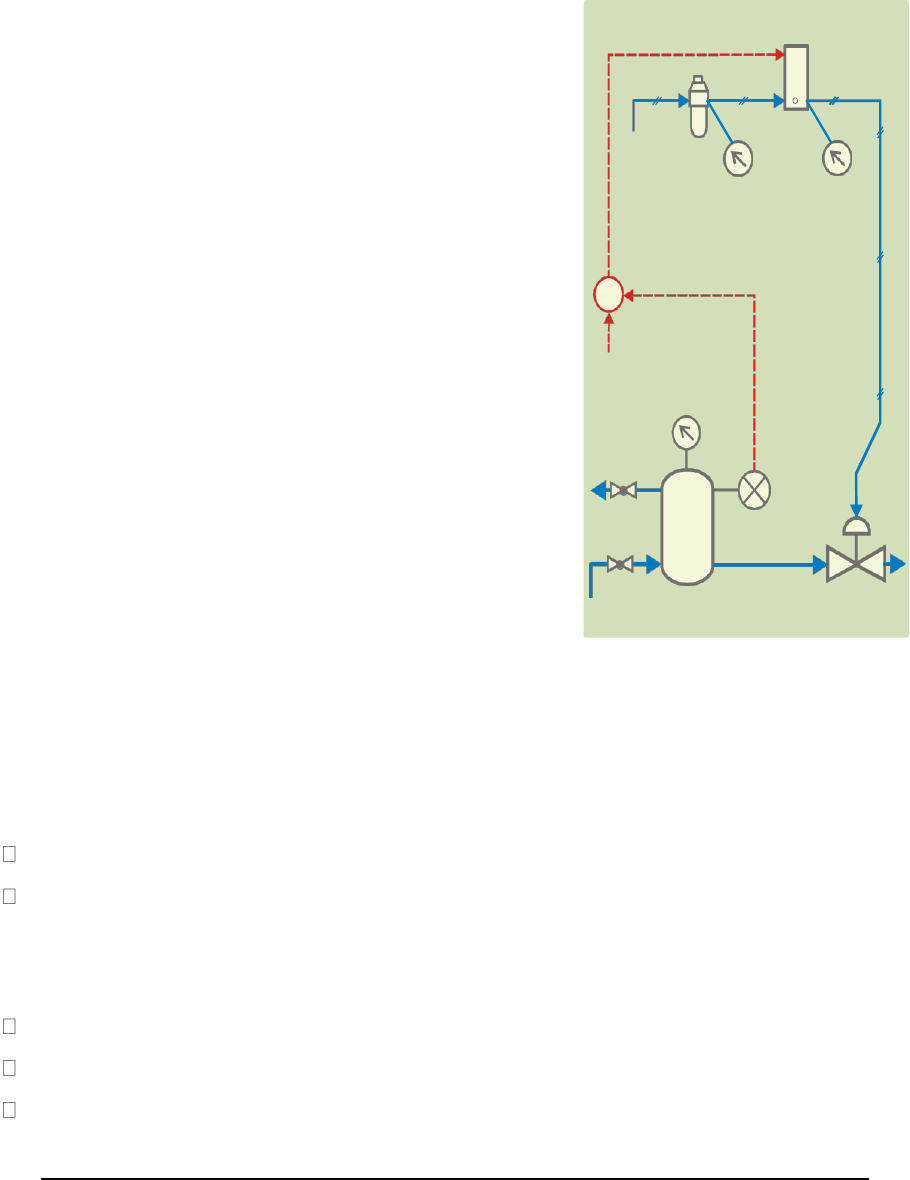
Theory: - Pressure control trainer is
designed for
understanding the basic
principles of pressure
control. The process
set up consists of
pressure vessel fitted with
pneumatic control
valve. Pressure
transmitter is used for pressure sensing.
The process parameter (Pressure) is
controlled by microprocessor based digital
indicating controller which
manipulates
pneumatic control valve fitted at
Outlet of pressure tank outlet through I/P
converter. These units along with necessary
piping are fitted on support housing designed
for tabletop mounting.
The controller can be connected to computer
through Ethernet /USB port for monitoring
the process in SCADA mode.
Procedure:-
Start up set up as explained in general instructions.
Click Select Experiment, select Open Loop and click Start
Close the control valve by increasing the controller output to 100%. Note down steady state
I/P Converter
Air Regulator
Air Supply
Supply Signal
Pressure
Pressure
Pressure Controller
Set Point
Tank
Pressure
Pressure
Vent Valve
Transmitter
N
N
Air
Process Tank
Control Valve
Supply

17-04-2017
23
Im314A
Department of Chemical Engineering, Veer Surendra Sai University of Technology Burla
process value.
Apply the step change by 10% to controller output and wait for the process value to reach the
steady state value. Note down the process value.
Repeat the above step until the controller output reaches to minimum 0%.
Observations
Tabulate the observations as follows
Controller output in %
Process Value in %
100
90
80
…
0
From the above data, note the output required for maintaining the process at desired set
points. (For particular vent valve opening).
Set the output of the controller to the noted value and at steady state apply the load change to the
process. Load change can be given by slightly varying the vent valve. Observe new steady state
process value.

17-04-2017
24
Im314A
Department of Chemical Engineering, Veer Surendra Sai University of Technology Burla
2. Aim of the experiment:-
To Study of on/off controller
Apparatus required:-
Pressure control trainer
Theory: - Pressure control trainer is
designed for
understanding the basic
principles of pressure
control. The process
set up consists of
pressure vessel fitted with
pneumatic control
valve. Pressure
transmitter is used for pressure sensing.
The process parameter (Pressure) is
controlled by microprocessor based digital
indicating controller which
manipulates
pneumatic control valve fitted at
Outlet of pressure tank outlet through I/P
converter. These units along with necessary
piping are fitted on support housing designed
for tabletop mounting.
The controller can be connected to computer
through Ethernet /USB port for monitoring
the process in SCADA mode.
Procedure:-
Start up set up as explained in general instructions.
Click Select Experiment, select On-Off Mode and click Start
Change Hysteresis value to 1 %.( Range 0.1-10%)
Change the values of the set point and observe the On-Off control operation.
I/P Converter
Air Regulator
Air Supply
Supply Signal
Pressure
Pressure
Pressure Controller
Set Point
Tank
Pressure
Pressure
Vent Valve
Transmitter
N
N
Air
Process Tank
Control Valve
Supply

17-04-2017
25
Im314A
Department of Chemical Engineering, Veer Surendra Sai University of Technology Burla
Observations
Observe that if process value exceeds the set point and increases above the value of (0.5x
Hysteresis), control valve is full open and if process value decreases below the set point by (0.5
x Hysteresis), the control valve closes fully i.e. controller operates like On/Off switch.
17-04-2017
26
Im314A
Department of Chemical Engineering, Veer Surendra Sai University of Technology Burla
3. Aim of the experiment:-
Study of proportional controller
Apparatus required:-
Pressure control trainer
Theory: - - Pressure control trainer is
designed for
understanding the basic
principles of pressure
control. The process
set up consists of
pressure vessel fitted with
pneumatic control
valve. Pressure
transmitter is used for pressure sensing.
The process parameter (Pressure) is
controlled by microprocessor based digital
indicating controller which
manipulates
pneumatic control valve fitted at
Outlet of pressure tank outlet through I/P
converter. These units along with necessary
piping are fitted on support housing designed
for tabletop mounting.
The controller can be connected to computer
through Ethernet /USB port for monitoring
the process in SCADA mode.
Procedure:-
Start up set up as explained in general
instructions.
Click Select Experiment, select P Mode and click Start
Keep the set point to 60%. Change output mode to Manual. Adjust output value so as to
match the process value with set point and apply this output value as bias value to the
controller. Adjust the proportional band to 50%.
Switch the controller to Auto mode.
Apply step change of 10% to set point and observe the response.
Switch the controller to Manual mode. Decrease proportional band to half of the previous
value & then shift controller to Auto mode. With each decrease, obtain a new response of
the
I/P Converter
Air Regulator
Air Supply
Supply Signal
Pressure
Pressure
Pressure Controller
Set Point
Tank
Pressure
Pressure
Vent Valve
Transmitter
N
N
Air
Process Tank
Control Valve
Supply

17-04-2017
27
Im314A
Department of Chemical Engineering, Veer Surendra Sai University of Technology Burla
step change. Ensure that the set point changes are around the same operating point (@
5-10%
only).
Using trial and error approach, find a value of proportional band so that the response to a step
change has at most one overshoot and one undershoot.
Set the controller to the settings obtained in the above step and wait for the system to reach at
steady state.
Observations
Observe steady state error decreases as proportional band decreases.
Observe the effect of very low proportional band values (system works in oscillatory mode).
Observe the response of the system at load change. Load change can be given by slightly
manipulating the vent valve of the tank.
Study of proportional integral controller

17-04-2017
28
Im314A
Department of Chemical Engineering, Veer Surendra Sai University of Technology Burla
4. Aim of the experiment:-
Study of proportional integral controller
Apparatus required:-
Pressure control trainer
Theory: - Pressure control trainer is
designed for
understanding the basic
principles of pressure
control. The process
set up consists of
pressure vessel fitted with
pneumatic control
valve. Pressure
transmitter is used for pressure sensing.
The process parameter (Pressure) is
controlled by microprocessor based digital
indicating controller which
manipulates
pneumatic control valve fitted at
Outlet of pressure tank outlet through I/P
converter. These units along with necessary
piping are fitted on support housing designed
for tabletop mounting.
The controller can be connected to computer
through Ethernet /USB port for monitoring
the process in SCADA mode.
Procedure:-
Start up set up as explained in general
instructions.
Click Select Experiment, select PI Mode and click Start
Adjust the process value by changing the output of controller in manual mode to a particular
pressure (set point =60%).
Set the proportional band estimated from Proportional control (from previous experiment).
Start with derivative time=0 and integral time=1000 sec., which will cut off the derivative
action and widen the effect of integral action.
Set the set point to desired pressure (@60%). Allow the process to reach at steady state.
Record the steady state error.
I/P Converter
Air Regulator
Air Supply
Supply Signal
Pressure
Pressure
Pressure Controller
Set Point
Tank
Pressure
Pressure
Vent Valve
Transmitter
N
N
Air
Process Tank
Control Valve
Supply
17-04-2017
29
Im314A
Department of Chemical Engineering, Veer Surendra Sai University of Technology Burla
Switch on the controller to manual mode. Reduce the integral time to half of the previous
value. Switch to Auto mode and apply step change to the set point by 2 to 3%. Note the
response of the system.
Using trial and error, find out an integral time, which gives satisfactory response to the step
change in set point.
Observations
Observe the effect of reducing integral time on offset and on the response of the process.
17-04-2017
30
Im314A
Department of Chemical Engineering, Veer Surendra Sai University of Technology Burla
5. Aim of the experiment:-
Study of proportional derivative controller
Apparatus required:-
Pressure control trainer
Theory: - Pressure control trainer is
designed for
understanding the basic
principles of pressure
control. The process
set up consists of
pressure vessel fitted with
pneumatic control
valve. Pressure
transmitter is used for pressure sensing.
The process parameter (Pressure) is
controlled by microprocessor based digital
indicating controller which
manipulates
pneumatic control valve fitted at
Outlet of pressure tank outlet through I/P
converter. These units along with necessary
piping are fitted on support housing designed
for tabletop mounting.
The controller can be connected to computer
through Ethernet /USB port for monitoring
the process in SCADA mode.
Procedure:-
Start up set up as explained in general
instructions.
Click Select Experiment, select PD Mode and click Start
Select PD controller. Set the proportional band estimated from Proportional control (P only).
Start with derivative time=0 and integral time=6000 sec., which will cut off the derivative
action and widen the effect of integral action.
Set the set point to desired pressure (@60%). Allow the process to reach at steady state.
Note
the response of the system.
Switch on the controller to manual mode. Increase the derivative time by 1 sec. Switch to
Auto mode and apply step change to the set point by 2 to 3%. Note the response of the
I/P Converter
Air Regulator
Air Supply
Supply Signal
Pressure
Pressure
Pressure Controller
Set Point
Tank
Pressure
Pressure
Vent Valve
Transmitter
N
N
Air
Process Tank
Control Valve
Supply

17-04-2017
31
Im314A
Department of Chemical Engineering, Veer Surendra Sai University of Technology Burla
system.
Increase the derivative time gradually and observe the process response for step change.
Observations
Observe the effect of increasing derivative time. Also note that the process may show offset
as
effect of integral action is cut off.

17-04-2017
32
Im314A
Department of Chemical Engineering, Veer Surendra Sai University of Technology Burla
6. Aim of the experiment:-
Study of proportional integral derivative controller
Apparatus required:-
Pressure control trainer
Theory: - Pressure control trainer is
designed for
understanding the basic
principles of pressure
control. The process
set up consists of
pressure vessel fitted with
pneumatic control
valve. Pressure
transmitter is used for pressure sensing.
The process parameter (Pressure) is
controlled by microprocessor based digital
indicating controller which
manipulates
pneumatic control valve fitted at
Outlet of pressure tank outlet through I/P
converter. These units along with necessary
piping are fitted on support housing designed
for tabletop mounting.
The controller can be connected to computer
through Ethernet /USB port for monitoring
the process in SCADA mode.
Procedure:-
Start up set up as explained in general
instructions.
Click Select Experiment, select PID mode and click Start
Switch the controller to manual mode.
Change the proportional band to the value that estimated in proportional controller. Set
integral time and derivative time based on the responses in previous experiments.
Change the controller to Auto mode. Apply step change by 2 to 3% to the set point and
observe the response of the process.
Change the proportional band, integral time, derivative time and observe the response of
the
process for step change for each change in setting.
I/P Converter
Air Regulator
Air Supply
Supply Signal
Pressure
Pressure
Pressure Controller
Set Point
Tank
Pressure
Pressure
Vent Valve
Transmitter
N
N
Air
Process Tank
Control Valve
Supply

17-04-2017
33
Im314A
Department of Chemical Engineering, Veer Surendra Sai University of Technology Burla
Observations
Compare the steady state response of the PID controller with P, PI and PD controller
obtained in the previous experiments.

17-04-2017
34
Im314A
Department of Chemical Engineering, Veer Surendra Sai University of Technology Burla
7. Aim of the experiment:-
Tuning of controller (Open loop method)
Apparatus required:-
Pressure control trainer
Theory: - Pressure control trainer is
designed for
understanding the basic
principles of pressure
control. The process
set up consists of
pressure vessel fitted with
pneumatic control
valve. Pressure
transmitter is used for pressure sensing.
The process parameter (Pressure) is
controlled by microprocessor based digital
indicating controller which
manipulates
pneumatic control valve fitted at
Outlet of pressure tank outlet through I/P
converter. These units along with necessary
piping are fitted on support housing designed
for tabletop mounting.
The controller can be connected to computer
through Ethernet /USB port for monitoring
the process in SCADA mode.
Procedure:-
Start up set up as explained in general
instructions.
Click Select Experiment, select Process Reaction and click Start
Adjust controller output, so that the process value is maintained at 60%.
Start data logging.
With the controller still in manual mode impose a step change apply a 20 - 30 % change to
controller output. (Open the control valve) Record the step response. Wait for the steady
state.
Stop data logging.
Plot the step response (Process reaction curve) from stored data. Find out the value of slope
at the
I/P Converter
Air Regulator
Air Supply
Supply Signal
Pressure
Pressure
Pressure Controller
Set Point
Tank
Pressure
Pressure
Vent Valve
Transmitter
N
N
Air
Process Tank
Control Valve
Supply

17-04-2017
35
Im314A
Department of Chemical Engineering, Veer Surendra Sai University of Technology Burla
point of inflection and time lag.
Calculate P I D settings for different modes.
Select PID Mode option for control from software. (Click on “Change Expt.” Button, click on
“Change”, Click on “PID Mode” button.) Switch on the controller to manual mode and Keep
the set point to 60%. Adjust output value so as to match the process value to set point.
Set the PID values obtained from the calculations. Switch on the controller to Auto mode.
Apply the step change & observe the response of the system. Allow the system to reach
steady state.
Observations:-
(Refer Theory process control for formula.)
Step change to the system P = Initial output - Final output of the controller.
Plot the graph of process value Vs Time on a graph paper.
From process reaction curve:
Slope of the process reaction curve R =
Time
lag L=
Calculate P, PI, and PID setting from above values.
Observe response of the system for different PID settings.

17-04-2017
36
Im314A
Department of Chemical Engineering, Veer Surendra Sai University of Technology Burla
8. Aim of the experiment:-
To study the Tuning of controller (Closed loop method)
Apparatus required:-
Pressure control trainer
Theory: - Pressure control trainer is
designed for
understanding the basic
principles of pressure
control. The process
set up consists of
pressure vessel fitted with
pneumatic control
valve. Pressure
transmitter is used for pressure sensing.
The process parameter (Pressure) is
controlled by microprocessor based digital
indicating controller which
manipulates
pneumatic control valve fitted at
Outlet of pressure tank outlet through I/P
converter. These units along with necessary
piping are fitted on support housing designed
for tabletop mounting.
The controller can be connected to computer
through Ethernet /USB port for monitoring
the process in SCADA mode.
Procedure:-
Start up set up as explained in general
instructions.
Click Select Experiment, select Close Loop and click Start
Set the proportional band value to maximum (Say 100). Set the controller to manual mode
and
adjust the output so that the process is nearly at set point (60%).
Set controller to auto mode and impose step on the process by moving the set point for a few
seconds & then return to its original value (or apply the step change to the set point of 5%).
Wait for some time & observe the response.
Decrease the proportional band to the half of previous and impose step on the process as
mentioned above. Wait for some time & observe the response.
I/P Converter
Air Regulator
Air Supply
Supply Signal
Pressure
Pressure
Pressure Controller
Set Point
Tank
Pressure
Pressure
Vent Valve
Transmitter
N
N
Air
Process Tank
Control Valve
Supply

17-04-2017
37
Im314A
Department of Chemical Engineering, Veer Surendra Sai University of Technology Burla
Repeat the above procedure and find out correct value of proportional band for which the
system just goes unstable i.e. continuous oscillations are observed in the output of
controller.
Record the ultimate proportional band and ultimate period from the response.
Calculate the PID values from the table. Select the PID controller and apply the parameter
values obtained from the above steps. Observe the response of the process to a step change
with
these settings.
Observations
Record the ultimate proportional band (Pbu) and ultimate period (Tu) from above
experiment.
Calculate PID values by referring theory part for different control actions.
Observe the process response for these settings.
Compare the values obtained with open loop response method.

17-04-2017
38
Im314A
Department of Chemical Engineering, Veer Surendra Sai University of Technology Burla
9. Aim of the experiment:-
To study the Tuning of controller (Using Auto Tuning method)
Apparatus Required:-
Pressure control trainer
Theory: - Pressure control trainer is
designed for
understanding the basic
principles of pressure
control. The process
set up consists of
pressure vessel fitted with
pneumatic control
valve. Pressure
transmitter is used for pressure sensing.
The process parameter (Pressure) is
controlled by microprocessor based digital
indicating controller which
manipulates
pneumatic control valve fitted at
Outlet of pressure tank outlet through I/P
converter. These units along with necessary
piping are fitted on support housing designed
for tabletop mounting.
The controller can be connected to computer
through Ethernet /USB port for monitoring
the process in SCADA mode.
Procedure:-
Start up set up as explained in general
instructions.
Click Select Experiment, select Auto tune and click Start
Wait Till Auto tune is complete. (Blinking of green LED stops).
Controller automatically finds the PB, IT & DT values.
Find out PID values at different set points /vent valve positions rates.
I/P Converter
Air Regulator
Air Supply
Supply Signal
Pressure
Pressure
Pressure Controller
Set Point
Tank
Pressure
Pressure
Vent Valve
Transmitter
N
N
Air
Process Tank
Control Valve
Supply

17-04-2017
39
Im314A
Department of Chemical Engineering, Veer Surendra Sai University of Technology Burla

17-04-2017
40
Im314A
Department of Chemical Engineering, Veer Surendra Sai University of Technology Burla
10. Aim of the experiment:-
To study stability of the system (Bode plot)
Apparatus required:-
Pressure control trainer
Theory: - Pressure control trainer is
designed for
understanding the basic
principles of pressure
control. The process
set up consists of
pressure vessel fitted with
pneumatic control
valve. Pressure
transmitter is used for pressure sensing.
The process parameter (Pressure) is
controlled by microprocessor based digital
indicating controller which
manipulates
pneumatic control valve fitted at
Outlet of pressure tank outlet through I/P
converter. These units along with necessary
piping are fitted on support housing designed
for tabletop mounting.
The controller can be connected to computer
through Ethernet /USB port for monitoring
the process in SCADA mode.
Procedure:-
Start up set up as explained in general
instructions.
Click Select Experiment, select Stability analysis and click Start
Select function generator to apply the sinusoidal input to the output of the controller.
Enter Reference point, Amplitude and Period.
Observe the sinusoidal output of the controller and sinusoidal response of the process.
Log the data for records.
Change the period and repeat the observation for 3-4 different values of the period.
I/P Converter
Air Regulator
Air Supply
Supply Signal
Pressure
Pressure
Pressure Controller
Set Point
Tank
Pressure
Pressure
Vent Valve
Transmitter
N
N
Air
Process Tank
Control Valve
Supply

17-04-2017
41
Im314A
Department of Chemical Engineering, Veer Surendra Sai University of Technology Burla
Observations
Form the data file stored note down the
Observe the output response of the process and note down the output amplitude. Measure
output wave period and note down as T sec. Measure the phase lag x and note down in sec.
Obs.
No.
Input
amplitude
A1 %
Output
amplitude
A2 %
Output Period
T in sec
Lag X
In sec
Frequency
Calculations
Calculate for each observation
Magnitude ratio as M = A2/A1
Phase angle = (X/T) x 360
Frequency = 1/T cycles
/
sec.
Draw the graphs of: Magnitude Vs frequency on log - log scale
Phase angle Vs frequency on semi-log coordinates.
Study the graph for stability conditions mentioned in theory

17-04-2017
42
Im314A
Department of Chemical Engineering, Veer Surendra Sai University of Technology Burla
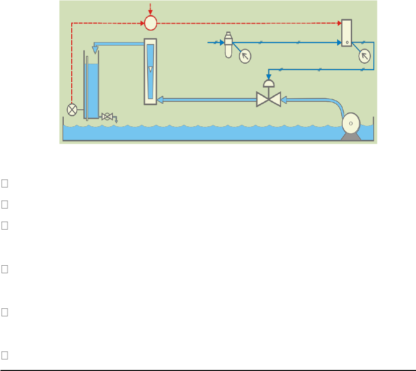
Level Controller
Set Point
I/P Converter
Air Regulator
Air Supply
Process Tank
Rotameter
Supply Pressure
Signal
Pressure
LT
Outlet Valve
Pump
Control Valve
Level Control Trainer
1.Aim of the experiment:-
To Study of open loop response (Manual control)
Apparatus required:-
Level control Trainer
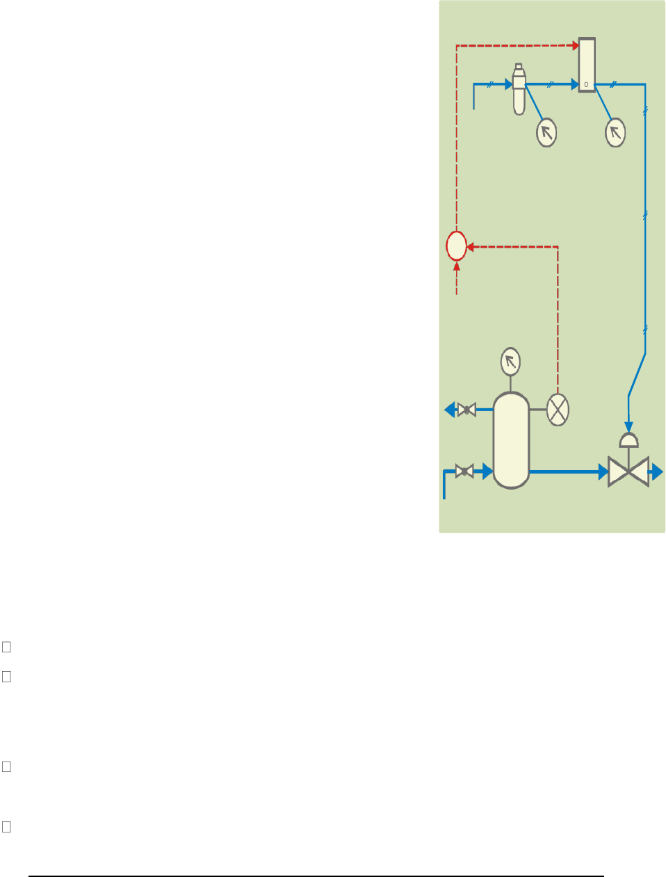
Theory: - Level control trainer is designed for understanding the basic principles of level
control. The process setup consists of supply water tank fitted with pump for water
circulation. The level transmitter used for level sensing is fitted on transparent process tank.
The process parameter (level) is controlled by microprocessor based digital indicating
controller which manipulates
pneumatic control valve through I/P converter. A pneumatic
control valve adjusts the water flow
in to the tank. These units along with necessary piping are
fitted on support housing designed for tabletop mounting.
The controller can be connected to computer through Ethernet
/
USB port for monitoring the
process in SCADA mode.
Procedure:-
Start up set up as explained in general instructions.
Click Select Experiment, select Open Loop and click Start
Open the control valve fully by decreasing the controller output to 0%. (Click on
Auto, Change it to Man then change OP to 0%)
Adjust the tank drain valve such that the tank level shall remain between 90 and 100%
Change the controller to Auto mode
Close the control valve by increasing the controller output to 100%.
Apply the step change by 10% to controller output in manual mode, wait for the level

17-04-2017
43
Im314A
Department of Chemical Engineering, Veer Surendra Sai University of Technology Burla
to reach the steady state value.
Repeat the above step until the controller output reaches to minimum i.e. 0%.
Observations
Tabulate the results as follows
Controller output in
%
Process Value in %
100
90
…
0
From the above data, note the output required for maintaining the level at desired set
points. (For particular drain valve opening).
Set the output of the controller to the noted value and at steady state apply the load change
to the process. Load change can be given by slightly varying the drain valve. Observe new
steady state process value.

17-04-2017
44
Im314A
Department of Chemical Engineering, Veer Surendra Sai University of Technology Burla
Level Controller
Set Point
I/P Converter
Air Regulator
Air Supply
Process Tank
Rotameter
Supply Pressure
Signal
Pressure
LT
Outlet Valve
Pump
Control Valve
2.Aim of the experiment:--
To Study of on/off controller
Apparatus Required:-
Level control Trainer
Theory: - - Level control trainer is designed for understanding the basic principles of level
control. The process setup consists of supply water tank fitted with pump for water
circulation. The level transmitter used for level sensing is fitted on transparent process tank.
The process parameter (level) is controlled by microprocessor based digital indicating
controller which manipulates
pneumatic control valve through I/P converter. A pneumatic
control valve adjusts the water flow
in to the tank. These units along with necessary piping are
fitted on support housing designed for tabletop mounting.
The controller can be connected to computer through Ethernet
/
USB port for monitoring the
process in SCADA mode.
Procedure:-
Start up set up as explained in general instructions.
Click Select Experiment, select On-Off Mode and click Start
Open the control valve fully by decreasing the controller output to 0%. (Click on Auto,
Change it to Man then change OP to 0%)
Adjust the tank drain valve such that the tank level shall remain between 90 and 100%
Change
the controller to Auto mode
Change Hysteresis value to 5%.(Range 0.1-10%)
Change the values of the set point and observe the On-Off control operation.
17-04-2017
45
Im314A
Department of Chemical Engineering, Veer Surendra Sai University of Technology Burla
Observations
Observe that if process value exceeds the set point and increases above the value of (0.5x
Hysteresis), control valve is fully closed and if process value decreases below the set point by
(0.5 x Hysteresis), the control valve opens fully i.e. controller operates like On/Off switch.

17-04-2017
46
Im314A
Department of Chemical Engineering, Veer Surendra Sai University of Technology Burla
Level Controller
Set Point
I/P Converter
Air Regulator
Air Supply
Process Tank
Rotameter
Supply Pressure
Signal
Pressure
LT
Outlet Valve
Pump
Control Valve
3. Aim of the experiment:-
Study of proportional controller
Apparatus Required:-
Level control Trainer
Theory: - Level control trainer is designed for understanding the basic principles of level
control. The process setup consists of supply water tank fitted with pump for water
circulation. The level transmitter used for level sensing is fitted on transparent process tank.
The process parameter (level) is controlled by microprocessor based digital indicating
controller which manipulates
pneumatic control valve through I/P converter. A pneumatic
control valve adjusts the water flow
in to the tank. These units along with necessary piping are
fitted on support housing designed for tabletop mounting.
The controller can be connected to computer through Ethernet
/
USB port for monitoring the
process in SCADA mode.
Procedure:-
Start up set up as explained in general instructions.
Click Select Experiment, select P Mode and click Start
Open the control valve fully by decreasing the controller output to 0%. (Click on Auto,
Change it to Man then change OP to 0%)
Adjust the tank drain valve such that the tank level shall remain between 90 and 100%
Change
the controller to Auto mode
Adjust the process value by switching the controller to manual mode to a particular level (say 50
%) on the screen and apply output of the controller as bias value. Change the proportional band
to 100%.
Switch the controller to auto mode.
Apply step change of 10% to set point.

17-04-2017
47
Im314A
Department of Chemical Engineering, Veer Surendra Sai University of Technology Burla
Switch the controller to manual mode. Decrease proportional band to half of the previous
value. With each decrease, obtain a new response of the step change. Ensure that the set
point changes are around the same operating point (Say 50%).
Observations
Observe the effect of very low proportional band values (system works as on-off control).
Observe the response of the system at load change. Load change can be given by slightly
manipulating the drain valve of the tank.

17-04-2017
48
Im314A
Department of Chemical Engineering, Veer Surendra Sai University of Technology Burla
Level Controller
Set Point
I/P Converter
Air Regulator
Air Supply
Process Tank
Rotameter
Supply Pressure
Signal
Pressure
LT
Outlet Valve
Pump
Control Valve
4 .Aim of the Experiment:-
Study of proportional integral controller
Apparatus Required:-
Level Control Trainer
Theory: - Level control trainer is designed for understanding the basic principles of level
control. The process setup consists of supply water tank fitted with pump for water
circulation. The level transmitter used for level sensing is fitted on transparent process tank.
The process parameter (level) is controlled by microprocessor based digital indicating
controller which manipulates
pneumatic control valve through I/P converter. A pneumatic
control valve adjusts the water flow
in to the tank. These units along with necessary piping are
fitted on support housing designed for tabletop mounting.
The controller can be connected to computer through Ethernet
/
USB port for monitoring the
process in SCADA mode.
Procedure:-
Start up set up as explained in general instructions.
Click Select Experiment, select PI Mode and click Start
Open the control valve fully by decreasing the controller output to 0%. (Click on
Auto, Change it to Man then change OP to 0%)
Adjust the tank drain valve such that the tank level shall remain between 90 and 100%
Change the controller to Auto mode
Set the proportional band estimated in Proportional control. Set derivative time to 0 sec and
integral time 6000 sec, which will cut off the derivative action and widen the effect of
integral action.
Set the set point to desired level value (@50%). Allow the process to reach at steady state.

17-04-2017
49
Im314A
Department of Chemical Engineering, Veer Surendra Sai University of Technology Burla
Record the steady state error.
Switch the controller to manual mode. Reduce the integral time to half of the previous
value. Switch to Auto mode and apply step change(+/- 10%) to the set point. Note the
response of the system.
Repeat above step to observe the effect of changes in Integral setting.
Observations
Observe the effect of reducing integral time on the response of the process.
17-04-2017
50
Im314A
Department of Chemical Engineering, Veer Surendra Sai University of Technology Burla
Level Controller
Set Point
I/P Converter
Air Regulator
Air Supply
Process Tank
Rotameter
Supply Pressure
Signal
Pressure
LT
Outlet Valve
Pump
Control Valve
5. Aim of the Experiment:-
Study of proportional derivative controller
Apparatus Required:-
Level control trainer
Theory: - Level control trainer is designed for understanding the basic principles of level
control. The process setup consists of supply water tank fitted with pump for water
circulation. The level transmitter used for level sensing is fitted on transparent process tank.
The process parameter (level) is controlled by microprocessor based digital indicating
controller which manipulates
pneumatic control valve through I/P converter. A pneumatic
control valve adjusts the water flow
in to the tank. These units along with necessary piping are
fitted on support housing designed for tabletop mounting.
The controller can be connected to computer through Ethernet
/
USB port for monitoring the
process in SCADA mode.
Procedure:-
Start up set up as explained in general instructions.
Click Select Experiment, select PD Mode and click Start
Open the control valve fully by decreasing the controller output to 0%. (Click on
Auto, Change it to Man then change OP to 0%)
Adjust the tank drain valve such that the tank level shall remain between 90 and 100%
Change the controller to Auto mode
Set the proportional band estimated from Proportional control (P only) Set derivative time
to 0 and integral time=6000 sec.
Set the set point to desired value. Allow the process to reach at steady state. Note the
response of the system.

17-04-2017
51
Im314A
Department of Chemical Engineering, Veer Surendra Sai University of Technology Burla
Switch the controller to manual mode Increase the derivative time by 1 sec. Switch to Auto
mode and apply step change to the set point by 5 to 10%. Note the response of the system.
Increase the derivative time gradually and observe the process response for step change.
Observations
Compare the steady state response of the PD controller with PI controller obtained in the
previous experiment.

17-04-2017
52
Im314A
Department of Chemical Engineering, Veer Surendra Sai University of Technology Burla
Level Controller
Set Point
I/P Converter
Air Regulator
Air Supply
Process Tank
Rotameter
Supply Pressure
Signal
Pressure
LT
Outlet Valve
Pump
Control Valve
6. Aim of the experiment:-
Study of proportional integral derivative controller
Apparatus Required:-
Level control Trainer
Theory: - Level control trainer is designed for understanding the basic principles of level
control. The process setup consists of supply water tank fitted with pump for water
circulation. The level transmitter used for level sensing is fitted on transparent process tank.
The process parameter (level) is controlled by microprocessor based digital indicating
controller which manipulates
pneumatic control valve through I/P converter. A pneumatic
control valve adjusts the water flow
in to the tank. These units along with necessary piping are
fitted on support housing designed for tabletop mounting.
The controller can be connected to computer through Ethernet
/
USB port for monitoring the
process in SCADA mode.
Procedure:-
Start up set up as explained in general instructions.
Click Select Experiment, select PID mode and click Start
Open the control valve fully by decreasing the controller output to 0%. (Click on
Auto, Change it to Man then change OP to 0%)
Adjust the tank drain valve such that the tank level shall remain between 90 and 100%
Change the controller to Auto mode
Switch the controller to manual mode.
Change the proportional band to the value that estimated in proportional controller. Set
integral time and derivative time based on the responses in previous experiments.
Adjust the set point to @ 50 %. Switch the controller to auto mode. Apply step change of

17-04-2017
53
Im314A
Department of Chemical Engineering, Veer Surendra Sai University of Technology Burla
10%. Observe the process response.
Change the proportional band, integral time, derivative time and observe the response of
the process for step change for each change in setting.
Observations:-
Compare the steady state response of the PID controller with P. PI and PD controller
obtained in the above experiment.

17-04-2017
54
Im314A
Department of Chemical Engineering, Veer Surendra Sai University of Technology Burla
Level Controller
Set Point
I/P Converter
Air Regulator
Air Supply
Process Tank
Rotameter
Supply Pressure
Signal
Pressure
LT
Outlet Valve
Pump
Control Valve
7. Aim of the Experiment:-
Tuning of controller (Open loop method)
Apparatus Required:-
Level control trainer
Theory: - Level control trainer is designed for understanding the basic principles of level
control. The process setup consists of supply water tank fitted with pump for water
circulation. The level transmitter used for level sensing is fitted on transparent process tank.
The process parameter (level) is controlled by microprocessor based digital indicating
controller which manipulates
pneumatic control valve through I/P converter. A pneumatic
control valve adjusts the water flow
in to the tank. These units along with necessary piping are
fitted on support housing designed for tabletop mounting.
The controller can be connected to computer through Ethernet
/
USB port for monitoring the
process in SCADA mode.
Procedure:-
Start up set up as explained in general instructions.
Click Select Experiment, select Process Reaction and click Start
Open the control valve fully by decreasing the controller output to 0%. (Click on
Auto, Change it to Man then change OP to 0%)
Adjust the tank drain valve such that the tank level shall remain between 90 and 100%
Change the controller to Auto mode
Adjust controller output, so that the process value is maintained at 50%.
Start data logging.
Apply a 20 - 30 % change to controller output. (Open the control valve) Record the step
response. Wait for the steady state.

17-04-2017
55
Im314A
Department of Chemical Engineering, Veer Surendra Sai University of Technology Burla
Stop data logging.
Plot the step response (Process reaction curve) from stored data. Find out the value of slope
at
the point of inflection and time lag.
Calculate P I D settings for different modes.
Select
close loop,
switch auto manual key to auto mode and then select controller to study.
Set the PID values obtained from the calculations. Apply the step change & observe the
response of the system. Allow the system to reach steady state.
Observations
(Refer Theory process control for formulae.)
Step
chan
g
e
t
o
the
s
y
stem
P
=
In
itial
o
u
tpu
t
-
Fi
n
al
o
u
tpu
t
o
f
the
c
o
n
tr
o
ll
er.
Plot the graph of process value Vs Time on a graph paper.rom process reaction curve:
Slope of the process reaction curve R =
Time lag L=
Calculate P, PI, and PID setting from above values.
Observe response of the system for different PID settings.

17-04-2017
56
Im314A
Department of Chemical Engineering, Veer Surendra Sai University of Technology Burla
Level Controller
Set Point
I/P Converter
Air Regulator
Air Supply
Process Tank
Rotameter
Supply Pressure
Signal
Pressure
LT
Outlet Valve
Pump
Control Valve
8. Aim of the experiment:-
Tuning of controller (Closed loop method)
Apparatus Required:-
Level control Trainer
Theory: -
Level control trainer is designed for understanding the basic principles of level
control. The process setup consists of supply water tank fitted with pump for water
circulation. The level transmitter used for level sensing is fitted on transparent process tank.
The process parameter (level) is controlled by microprocessor based digital indicating
controller which manipulates
pneumatic control valve through I/P converter. A pneumatic
control valve adjusts the water flow
in to the tank. These units along with necessary piping are
fitted on support housing designed for tabletop mounting.
The controller can be connected to computer through Ethernet
/
USB port for monitoring the
process in SCADA mode.
Procedure:-
Start up
set up as explained in general instructions.
Click Select Experiment, select Close Loop and click Start
Open the control valve fully by decreasing the controller output to 0%. (Click on
Auto, Change it to Man then change OP to 0%)
Adjust the tank drain valve such that the tank level shall remain between 90 and 100%
Change the controller to Auto mode
Select P controller only. Set the proportional band value to maximum (Say 100). Set the
controller to manual mode and adjust the output so that the process value reaches to 50%.
Switch the controller to auto mode and decrease the proportional band and apply the step
change to the set point and observe the process response.

17-04-2017
57
Im314A
Department of Chemical Engineering, Veer Surendra Sai University of Technology Burla
Repeat the above procedure and find out correct value of proportional band for which the
system just goes unstable i.e. continuous oscillations are observed in the output of
controller.
Record the ultimate proportional band and ultimate period from the response.
Calculate the PID values from the table. Select the PID controller and apply the parameter
values obtained from the above steps. Observe the response of the process to a step change
with these settings.
Observations
Record the ultimate proportional band (
Pbu
) and ultimate period (
Tu
) from above
experiment.
Calculate PID values by referring theory part for different control actions.bserve the process
response for these settings.
Compare the values obtained with open loop response method.

17-04-2017
58
Im314A
Department of Chemical Engineering, Veer Surendra Sai University of Technology Burla
Level Controller
Set Point
I/P Converter
Air Regulator
Air Supply
Process Tank
Rotameter
Supply Pressure
Signal
Pressure
LT
Outlet Valve
Pump
Control Valve
9. Aim of the experiment:-
Tuning of controller (Using Auto Tuning method)
Apparatus Required:-
Level Control Trainer
Theory: - Level control trainer is designed for understanding the basic principles of level
control. The process setup consists of supply water tank fitted with pump for water
circulation. The level transmitter used for level sensing is fitted on transparent process tank.
The process parameter (level) is controlled by microprocessor based digital indicating
controller which manipulates
pneumatic control valve through I/P converter. A pneumatic
control valve adjusts the water flow
in to the tank. These units along with necessary piping are
fitted on support housing designed for tabletop mounting.
The controller can be connected to computer through Ethernet
/
USB port for monitoring the
process in SCADA mode.
Procedure:-
Start up set up as explained in general instructions.
Click Select Experiment, select Auto tune and click Start
Wait Till Auto tune is complete. (Blinking of green LED stops).
Controller automatically finds the PB, IT & DT values.
Find out PID values at different set points /flow rates

17-04-2017
59
Im314A
Department of Chemical Engineering, Veer Surendra Sai University of Technology Burla
Observations
The controller has preprogrammed logic for finding “Auto tune” values. Based on the
response of the process the controller calculates PID values or comes out without finding the
“Auto tune” values.

17-04-2017
60
Im314A
Department of Chemical Engineering, Veer Surendra Sai University of Technology Burla
Level Controller
Set Point
I/P Converter
Air Regulator
Air Supply
Process Tank
Rotameter
Supply Pressure
Signal
Pressure
LT
Outlet Valve
Pump
Control Valve
10. Aim of the Experiment:-
To study stability of the system (Bode plot)
Apparatus required:-
Level Control Trainer
Theory: - Level control trainer is designed for understanding the basic principles of
level control. The process setup consists of supply water tank fitted with pump for
water circulation. The level transmitter used for level sensing is fitted on transparent
process tank. The process parameter (level) is controlled by microprocessor based
digital indicating controller which manipulates
pneumatic control valve through I/P
converter. A pneumatic control valve adjusts the water flow
in to the tank. These units
along with necessary piping are fitted on support housing designed for tabletop
mounting.
The controller can be connected to computer through Ethernet
/
USB port for
monitoring the process in SCADA mode.
Procedure:-
Start up set up as explained in general instructions.
Click Select Experiment, select Stability analysis and click Start
Open the control valve fully by decreasing the controller output to 0%. (Click
on Auto, Change it to Man then change OP to 0%)
Adjust the tank drain valve such that the tank level shall remain between 90 and
100%
Change the controller to Auto mode
Start data logging.
Select function generator to apply the sinusoidal input to the output of the controller.

17-04-2017
61
Im314A
Department of Chemical Engineering, Veer Surendra Sai University of Technology Burla
Enter Reference point, Amplitude and Period.
Observe the sinusoidal output of the controller and sinusoidal response of the process.
Log the data for records.
Change the period and repeat the observation for 3-4 different values of the period.
Repeat above procedure for different amplitude and period values.
Observations
From the data file stored observe the output response of the process and note
down the output amplitude.
Measure output wave period and note down as T sec. Measure the phase lag x and
note
down in sec.
