
909-938-7721
advancedev.com

Preface
Dear Users,
Great thanks for purchasing our company's electric
cars. While adopting advanced technology of Europe
and the US and main imported components, the cars are
also with the innovative design, luxury professional
painting and high strength steel welding material, all of
which make our cars look fashionable, reliable, beautiful
and excellent in performance. With lightweight, strong
climbing ability, free pollution, low noise, convenient
charging, good braking performance and reasonable
price, our cars are the most advanced in the electric car
field at present.
In order to help users operate and maintain the car
correctly, make the car play the best performance
and prolong its working time, hereby we make
the operation manual. Please read it carefully.
The product is always in improving. If the manual
doesn't match with the real product, the read
product is the standard.
Note: This bus is mainly designed for relaxation,
sightseeing, tourism, thus suitable for used in special area
like tourism scenic area, community, pedestrian mall etc.
IIMMPPOORRTTAANNTT MMAANNUUAALL IINNFFOORRMMAATTIIOONN
Particularly important information
is distinguished by using the
following symbols and notes:
&
CAUTION
I
NOTE:
AdvancedEV continually seeks
improvement in product quality.
Even though this manual contains
the latest product information
available at the time of printing,
there may be minor discrepancies
between your golf car and this
manual. If you have any question
concerning this manual, please
contact your AdvancedEV dealer
and we will work it out.
This manual should be considered
as a permanent part of your golf car
and should stay with the car when
the car is sold.
Read and understand the
manual completely before
operating your golf car.
NOTE:
This message provides additional
main information.
This message describes special
precautions that must be taken so
as to avoid damage to the car.
Failure to follow WARNING
instructions could result in
severe injury or death to the golf
car passengers, bystanders, or
the person driving the golf car.

Preface
Dear Users,
Great thanks for purchasing our company's electric
cars. While adopting advanced technology of Europe
and the US and main imported components, the cars are
also with the innovative design, luxury professional
painting and high strength steel welding material, all of
which make our cars look fashionable, reliable, beautiful
and excellent in performance. With lightweight, strong
climbing ability, free pollution, low noise, convenient
charging, good braking performance and reasonable
price, our cars are the most advanced in the electric car
field at present.
In order to help users operate and maintain the car
correctly, make the car play the best performance
and prolong its working time, hereby we make
the operation manual. Please read it carefully.
The product is always in improving. If the manual
doesn't match with the real product, the read
product is the standard.
Note: This bus is mainly designed for relaxation,
sightseeing, tourism, thus suitable for used in special area
like tourism scenic area, community, pedestrian mall etc.
I
I
M
M
P
P
O
O
R
R
T
T
A
A
N
N
T
T
M
M
A
A
N
N
U
U
A
A
L
L
I
I
N
N
F
F
O
O
R
R
M
M
A
A
T
T
I
I
O
O
N
N
Particularly important information
is distinguished by using the
following symbols and notes:
&
CAUTION
I
NOTE:
AdvancedEV continually seeks
improvement in product quality.
Even though this manual contains
the latest product information
available at the time of printing,
there may be minor discrepancies
between your golf car and this
manual. If you have any question
concerning this manual, please
contact your AdvancedEV dealer
and we will work it out.
This manual should be considered
as a permanent part of your golf car
and should stay with the car when
the car is sold.
Read and understand the
manual completely before
operating your golf car.
NOTE:
This message provides additional
main information.
This message describes special
precautions that must be taken so
as to avoid damage to the car.
Failure to follow WARNING
instructions could result in
severe injury or death to the golf
car passengers, bystanders, or
the person driving the golf car.

2
4
9
12
15
25
26
28
30
I
I
m
m
p
p
o
o
r
r
t
t
a
a
n
n
t
t
L
L
a
a
b
b
e
e
l
l
s
s
C
C
o
o
n
n
t
t
e
e
n
n
t
t
O
O
p
p
e
e
r
r
a
a
t
t
i
i
o
o
n
n
a
a
l
l
S
S
a
a
f
f
e
e
t
t
y
y
S
S
t
t
r
r
u
u
c
c
t
t
u
u
r
r
e
e
a
a
n
n
d
d
S
S
p
p
e
e
c
c
i
i
f
f
i
i
c
c
a
a
t
t
i
i
o
o
n
n
s
s
O
O
p
p
e
e
r
r
a
a
t
t
i
i
o
o
n
n
A
A
n
n
d
d
C
C
o
o
n
n
t
t
r
r
o
o
l
l
P
P
r
r
e
e
O
O
p
p
e
e
r
r
a
a
t
t
i
i
o
o
n
n
M
M
a
a
i
i
n
n
t
t
e
e
n
n
a
a
n
n
c
c
e
e
S
S
t
t
o
o
r
r
a
a
g
g
e
e
V
V
e
e
h
h
i
i
c
c
l
l
e
e
M
M
a
a
i
i
n
n
t
t
e
e
n
n
a
a
n
n
c
c
e
e
A
A
n
n
d
d
A
A
f
f
t
t
e
e
r
r
-
-
s
s
a
a
l
l
e
e
s
s
S
S
e
e
r
r
v
v
i
i
c
c
e
e
W
W
i
i
r
r
i
i
n
n
g
g
D
D
i
i
a
a
g
g
r
r
a
a
m
m
C
C
o
o
n
n
t
t
r
r
o
o
l
l
l
l
e
e
r
r
T
T
r
r
o
o
u
u
b
b
l
l
e
e
S
S
h
h
o
o
o
o
t
t
i
i
n
n
g
g
P
P
r
r
o
o
c
c
e
e
s
s
s
s

are released
when batteries
are charged or
discharged. Keep
well ventilated.
Keep sparks,
flames and
cigarettes away.
Shield eyes
when working
near batteries.
Operation Essentials
Windshields do not
provide protection
from other flying
objects.
Before operating:
1. Read this manual and all the other operations or labels marked on the car body
before operating.
2. Only authorized people should drive the car only in the designated area.
3. Do not OVERLOAD.
4. Do not drive the car if drinking any alcohol or having any drugs which could
distract the driver's vision and judgment.
When operating:
1. Keep your body in the car and keep well-seated when the car starts moving.
2. Do not start the car until all passengers are seated.
3. Keep your hands on the steering wheel and your eyes on the path ahead.
4. Be especially careful when backing the car in crowded places. Please keep
watching back and roll back slowly.
5. Avoid sudden start and brake.
6. Please accelerate or decelerate the car according to the ground condition.
7. Do not turn the steering wheel too sharply at high speed.
8. Keep driving slowly straight up or straight down, not at one same angle when
on slopes.
Do not overload or make any modification towards spare
parts without permission.
SAFETY AND
INSTRUCTION
LABELS
Important Labels
Safety Operation

13
10
11
12
Top roof rear support
Golf bag support
Golf bag box
10
11
Front wheel trims
12
13
Rear wheel trims
17
18
19
20
21
22 22
22442266
2277
14
15
16
17
18
19
20
Steering wheel
Combination switch
Glove box cover / L
Armrest
Glove box cover / R
21
Cup base
22
23
24
25
26
27
Caddie pedal
Rear cover
3
4
ADVENT 2 vehicle structure:
Top roof
Front windshield
Windshield frame
Front cover
Front headlight /R
Front bumper
Front headlight /L
Side sill
Brake pedal
Accelerator pedal
Tail light /R
Tail light /L
Rear wheel
Front wheel
1. Keep your hands on the steering
wheel and your eyes on the path ahead.
2. Be especially careful when backing
in the car in crowded places. Please
keep watching back and roll back
slowly.
3. Avoid sudden and strong shock of
the car and change to the proper speed
according to the ground condition.
4. Do not turn the steering wheel too
sharply when at high speed.
5. Keep driving slowly straight up or
straight down, not at one same angle.
6. Do not make any modifaction or
addition about the operation safety and
loading capacity, and this whole
manual.
Structure And Specifications
Operation Safety

13
10
11
12
Top roof rear support
Golf bag support
Golf bag box
10
11
Front wheel trims
12
13
Rear wheel trims
17
18
19
20
21
2
2
2
2
2
2
4
4
2
2
6
6
2
2
7
7
14
15
16
17
18
19
20
Steering wheel
Combination switch
Glove box cover / L
Armrest
Glove box cover / R
21
Cup base
22
23
24
25
26
27
Caddie pedal
Rear cover
3
4
ADVENT 2 vehicle structure:
Top roof
Front windshield
Windshield frame
Front cover
Front headlight /R
Front bumper
Front headlight /L
Side sill
Brake pedal
Accelerator pedal
Tail light /R
Tail light /L
Rear wheel
Front wheel
1. Keep your hands on the steering
wheel and your eyes on the path ahead.
2. Be especially careful when backing
in the car in crowded places. Please
keep watching back and roll back
slowly.
3. Avoid sudden and strong shock of
the car and change to the proper speed
according to the ground condition.
4. Do not turn the steering wheel too
sharply when at high speed.
5. Keep driving slowly straight up or
straight down, not at one same angle.
6. Do not make any modifaction or
addition about the operation safety and
loading capacity, and this whole
manual.
Structure And Specifications
Operation Safety

5
10
Top roof rear support
Second row backrest
Second row seat cushion
10
11
13
Front cover
17
18
19
20
21
2222
2244
2266
14
15
16
17
18
19
21
Windshield
Windshield frame
Steering wheel
Combination switch
25
Tail light/R
26
27
28
29
30
31
Armrest/L
6
17
18
19
20
22
Top roof rear support
Rear seat armrest
Caddie plate
10
11
Front wheel trims
12
13
Rear wheel trims
14
15
16
17
18
19
20
Steering wheel
Combination switch
Glove box cover /L
Armrest
Glove box cover /R
21
Cup base
22
23
24
25
26
27
Rear cover
ADVENT 4 vehicle structure:
13
10
11
12
23
21
242528
Front cover
Windshield
Windshield frame
Rear seat backrest
2627
Rear wheel/R
Rear seat cushion
Rear wheel/L
Armrest for driver's seat
28
Side sill
11
12
13
14
15
2277
2299
3300
3311
3322
3333
3344
2288
ADVENT 4F vehicle structure:
Rear wheel trims
Rear cover
Font backrest
Front seat cushion
Front wheel trims
Front bumper
12
Front headlight / R
Glove box cover /L
Armrest/R
20
22
23
24
Accelerator pedal
Glove box cover / R
Cup base
Cargo box
32
33
34
Rear bumper
Rear wheel/R
Rear wheel/L
Side sill
Front seat box
Front wheel/L
Armrest
Front wheel / L
Top roof
Front headlight /L
Front bumper
Front headlight /R
Brake pedal
Accelerator pedal
Top roof
Front headlight / L
Brake pedal
Tail light/L
Structure And SpecificationsStructure And Specifications
Structure And Specifications

5
10
Top roof rear support
Second row backrest
Second row seat cushion
10
11
13
Front cover
17
18
19
20
21
2
2
2
2
2
2
4
4
2
2
6
6
14
15
16
17
18
19
21
Windshield
Windshield frame
Steering wheel
Combination switch
25
Tail light/R
26
27
28
29
30
31
Armrest/L
6
17
18
19
20
22
Top roof rear support
Rear seat armrest
Caddie plate
10
11
Front wheel trims
12
13
Rear wheel trims
14
15
16
17
18
19
20
Steering wheel
Combination switch
Glove box cover /L
Armrest
Glove box cover /R
21
Cup base
22
23
24
25
26
27
Rear cover
ADVENT 4 vehicle structure:
13
10
11
12
23
21
242528
Front cover
Windshield
Windshield frame
Rear seat backrest
2627
Rear wheel/R
Rear seat cushion
Rear wheel/L
Armrest for driver's seat
28
Side sill
11
12
13
14
15
2
2
7
7
2
2
9
9
3
3
0
0
3
3
1
1
3
3
2
2
3
3
3
3
3
3
4
4
2
2
8
8
ADVENT 4F vehicle structure:
Rear wheel trims
Rear cover
Font backrest
Front seat cushion
Front wheel trims
Front bumper
12
Front headlight / R
Glove box cover /L
Armrest/R
20
22
23
24
Accelerator pedal
Glove box cover / R
Cup base
Cargo box
32
33
34
Rear bumper
Rear wheel/R
Rear wheel/L
Side sill
Front seat box
Front wheel/L
Armrest
Front wheel / L
Top roof
Front headlight /L
Front bumper
Front headlight /R
Brake pedal
Accelerator pedal
Top roof
Front headlight / L
Brake pedal
Tail light/L
Structure And SpecificationsStructure And Specifications
Structure And Specifications

8
ADVENT8ADVENT 6
25km/h
1.6m
120mm
<6m
3615*1210*1905mm
4150*1210*1900mm
3630*1210*1840mm
585kg(with b attery)
1800*1150*265mm
500kg
75-90km(Flat road)
70-85km(Flat road)
70-80km(Flat road)
18%
10%
10%
15%
2485mm
3260mm
3260mm
4.45m
4.5m
5.8m
Front 905mm/Rear 1 000mm
Front 895mm/Rear 1 000mm
8.5kwh 9kwh
150mm
4405*1210*1915mm
700kg(with b attery)
695kg(with b attery)
605kg(with b attery)
6-person
8-person 2-person
NO
NO
70-85km(Flat road)
10%
20%
20%
20%
2425mm
Front 905mm/Rear 1 000mm
9.5kwh
1170*610*265mm
50kg
5.8m
NO
NO
AC Toyota 48M350B—350A controller
AdvancedEV maintenance-free battery 8V-150AHx6pcs( 3 hrs rate)
32V/4KW AC Asynchronous Motor
Smart battery charger 48V/25A
、 Charging time < 8 hours(with discharge rate of 80%)
Four wheel hydraulic disc brake + Electromagnetic brake parking
7
Body configuration
ADVENT 2
ADVENT 4F
Controller
Charger
DCconverter
AC Toyota 48M350B—350A controller
AdvancedEV maintenance-free battery 8V-150AHx6pcs( 3 hrs rate)
32V/4KW AC Asynchronous Motor
Smart battery charger 48V/25A
、 Charging time < 8 hours(with discharge rate of 80%)
Aluminium alloy profile frame+PP injection molded
Configuration and Parameter
Four wheel hydraulic disc brake + Electromagnetic brake parking
Front body, seat barrel and rear body are PP injection molded; Aluminum profile roof support
with matte black painting (ADVENT.4 with aluminum alloy box)
25km/h
1.6m
120mm
<6m
2740*1210*1820mm
2785*1210*1910mm
3360*1210*1900mm
560kg(with b attery) 585kg(with b attery)
590kg(with b attery)
2-person
4-person
1170*610*265mm
50kg
80-100km(Flat road)
75-90km(Flat road)
30%
25%
18%
30%
25%
25%
1670mm
2485mm
3.2m
4.45m
Front 905mm/Rear 1000mm
8kwh 9kwh
ADVENT 4
NO
NO
80-100km(Flat road)
Electronic system
Battery
Motor
Front windshield
and wiper
Top roof
Seat
Floor
Body
&Finish
Side mirrors
Lights and
warning signals
Dash
Steering system
Braking system
Front suspension
system
Tire diameter
Rear suspension
system
Max speed
Minimum ground
clearance
Brake stability
Braking distance
Overall L
*W*H
Curb weight
Seating capacity
Container size
Container load
Mileage(Km)
Max climbing
ability
Grade parking
performance
Wheel base
Minimum
turning radius
Wheel track
Energy consumption
(per 100Km)
Technical parameter
High power non-isolated DC-DC 48V/12V-180W
Acrylic glass;Optional with toughened glass+wiper
Ergonomic seat,leather fabric
Aluminum profile non-slip floor, high strength structure, corrosion resistance, aging resistance
One adjustable and foldable external side mirror on each side
LED headlights (low beams,high beams,turn signals,daytime running light s and position lights)
LED taillights (brake lights,position lights, turn signals),Snail horn,reversing buzzer
Plastic forming instrument dash,LED speedometer,key switch,single-arm combination switch,gear switch,
cup base;double USB power supply,12V power supply.Optional with multi-media audio and video system
(backup camera,video player)
Double-ended Rack and Pinion,self-adjusting
Double swing arm independent front suspension + coil spring + hydraulic shock absorbers
205/65-10(Tire diameter 520mm) with 10 inch es steel rim
Integral type transaxle , gear ratio 12.31:1, coil spring + hydraulic
shock absorbers + rear stabilizing bar
Integral type transaxle,
gear ratio 16:1, coil spring
+ hydraulic shock absorbers
+ rear stabilizing bar
High power non-isolated DC-DC 48V/12V-180W
Acrylic glass; Optional with toughened glass+wiper
Aluminium alloy profile frame+PP injection molded
Ergonomic seat, leather fabric
Aluminum profile non-slip floor, high strength structure, corrosion resistance, aging resistance
Front body, seat barrel and body are PP injection molded;Aluminum Aluminum profile roof support
with matte black painting (H8 seat bucket and box are made of high strength aluminum profile)
One adjustable and foldable external side mirror on each side
LED headlights (low beams, high beams, turn signals, daytime running lights and position lights)
LED taillights (brake lights, position lights, turn signals),snail horn, reversing buzzer
Plastic forming instrument dash,LED speedometer,key switch,single-arm combination switch,gear switch,
cup base;double USB power supply,12V power supply. Optional with multi-media audio and video system
(backup camera,video player)
Double-ended rack and pinion,self-adjusting
Double swing arm independent front suspension + coil spring + hydraulic shock absorbers
205/65-10(Tire diameter 520mm)with 10 inch es steel rim
Integral type transaxle , gear ratio 16:1,
coil spring + hydraulic shock absorbers + rear stabilizing bar
Integral type transaxle,
gear ratio 16:1,coil spring
+ hydraulic shock absorbers
+ rear stabilizing bar
Front body,seat barrel and rear body are PP injection molded; Aluminum profile roof support
with m atte b lack p ainting (A827.4 w ith a lumininm alloy b ox)
Structure And Specifications
Structure And Specifications

9
10
Turning on Main Switch
1. Shifting the switch to RUN position
then can turn on the power supply of
car.
2. Shifting the switch to OFF position
then can turn off the power supply of
car.
Key Switch
1. Plugging the key and turn right then
can turn on the key switch (Note:
Shifting the F/R switch to the middle
position before turning on key switch).
2. Turning left and then can turn off the
switch. Switch can be removed only at
this state.
Completely stopping car before shifting F/R switch. When shifting F/R
switch, please turn switch to middle position for 2s at first, then choosing
Forward switch or Reverse switch. Don't shift F/R switch in a hurry in
case that the sensor will be burnt or switch will be out of use.
Forward/Reverse Switch
The Forward/Reverse Switch is used to
shift the car to forward, reverse or
stop. Forward for upward, Reverse for
downward, Park for middle. When
choosing reverse switch, the reverse
buzzer sounds.
Combination Switch
1. Turn signal: Move the turn signal lever forward, left
turn signal flashes. At the same time, you'll be able to
see a flashing arrow directed to the left on your
instrument cluster. Move the turn signal lever
backward, the arrow directed to the right on.
2. Low beam: Front part of the lever can be pushed
and pulled. After the vehicle is started, push the lever
forward to turn on low bean and backward to turn off.
3. High beam: move the lever upwards (steering wheel
surface) to turn on high beam. Releasing the lever, it
will automatically return to original position, and the
high beam can be permanently on.
4. Horn: Press lightly on the end of lever, where horn
button is located.
Glove box lock
There are one glove box on each side of instrument
panel, which can be used to store goods. When the
glove box cover is not locked, press the lock head to
open the cover.
Unlock: Insert the key into the lock, rotate in the
clockwise direction to unlock, and then remove the key.
Locking: Close the box cover, insert the key and rotate
in the counterclockwise direction to lock, and then
remove the key.
Operation And Control
Operation And Control

11
12
1
2
3
4
2
3
4
Be sure that the main switch key
is removed before performing the
pre-operating checks to prevent
accidental starting, and apply the
parking brake to keep the car
from moving.
Brake pedal
If reducing speed while car is running,
put your right foot on brake pedal and
step on it, then can reduce speed till car
stops.
Attention: Avoid quick brake!
Accelerator pedal
Turn on the key switch, choose forward
and backward, release brake, put your
right foot on the accelerator pedal, soft
step down the pedal to start the car.
Attention: Don't step down the pedal to
the end in rush.
Instrument cluster
Display the current vehicle status, rotate
speed, speed per hour, battery power,
mileage, light signal etc. During the
driving, you can check whether it is
normal according to the status of the
indicator light in the instrument cluster.
1
Instrument cluster lighting diagram
Rotating speed
Speed per hour
Battery power
Mileage
SEAT
Opening the seat for checking
and servicing
Body and Chassis:
Before each use, carefully inspect the
car body and chassis for damage
and/or missing parts.
Batteries
Tire condition
Steering system
Back-up buzzer
Pedal operation
Body and chassis
PRE-OPERATION CHECKLIST
Before each use, please check the
following
Pre operation checks should be made
each time you use your golf car. Get in
the habit of performing the following
checks in the same way so that they
become second nature.
Operation And Control
Pre Operation

13
14
40PSI
Steering system
Check the steering system whether there
is too much empty steering
a. Put the steering wheel up and down,
front and back
b. Turning the steering wheel left or right
If you find too much empty steering or
hear noise, it means some parts wrong and
please contact your dealer immediately.
Reverse alarm
Turn the F/R switch to "R" for checking
reverse alarm.
Pedal operation
Check the pedals operation, if it's abnormal,
contact dealer immediately.
Brake pedal
When step down the pedal, you feel well,
release it to be in the original position.
Brake pedal
Accelerator pedal
Accelerate pedal
Check the flexibility and reliability of
pedal, it returns to original position after
step down.
BATTERY
Charge batteries before every use.
See charging steps in chapter 6.
Check that the batteries are held
securely in place to prevent the
batteries from vibration or jarring.
Also check that no prevent battery
acid from spilling from the battery.
Check the battery terminals for
corrosion.
TIRE CONDITION
Check the tire air pressure before the
operation of car.
Wear limit
Tire wear limit
Check the tire surface for damage,
cracks or embedded objects. When
tire tread wears down to 0.04(1mm),
replace the tire.
Pre Operation
Pre Operation

15
16
Battery electrolyte is poisonous and
dangerous, causing severe burns, etc. It
contains sulfuric acid. Avoid contacting
with skin, eyes and clothes.
Antidote:
EXTERNAL: Flush with water
INTERNAL: Drink large quantities of water
or milk. Follow with milk of magnesia,
beaten egg, or vegetable oil.
Call physician immediately.
EYES: Flush with water for 15 minutes
and get prompt medical attention.
Batteries produce explosive gases. Keep
sparks, flames and cigarettes away.
Make sure it is ventilated when charging
or using in enclosed space. Always shield
eyes when working near batteries.
BATTERY CHARGING
BATTERY CARE
CAUTION
Keep out reach of children.
Batteries provide power for your electronic car and must
be properly maintained and recharged for maximum
performance and service life. The ways to maintain your
batteries
1. Clean the top of the batteries with soda water if
necessary to remove corrosion.
2. Check the fluid level before and after charging.
Do not allow cleaning material to
enter battery cells.
Read and understand the manual
provided with your car's battery
charger before charging batteries.
Explosive hydrogen gas is produced
while batteries are being charged.
Only charge batteries in well
ventilated areas (A minimum of 5 air
changes per hour is recommended)
Use battery chargers that are only
used for this car. Thoroughly read
and understand the manual.
Follow the instructions contained in
your battery charger's owner's manual
to charge the batteries in your car.
The following is a summary of the
charging steps. Do not attempt to
recharge your car's batteries without
thoroughly reading and understanding
the manual.
Connect the charger properly with the
plug case (see charger's owner's
manual). Do not insert the AC output
plug into the car directly.
CAUTION
Maintenance
Maintenance

17
18
Before charging:
Only add distilled water. If fluid is below
the top of the plates, add just enough to
cover plates.
After charging:
Check that the fluid level is appropriately
1/4 to 1/2 inch above the plates and 1/4 to
3/8 inch below the level is low. Add
distilled water carefully. Adding distilled
water after charging helps prevent boiling
over.
A Battery cap
B Plates
C Maximum fluid level
D Minimum fluid level
Note: Only lead-acid batteries
need to add battery water,
maintenance-free batteries do not
need.
Normal tap water contains minerals
which are harmful to a battery;
therefore, refill only with distilled water.
3. Using a hydrometer, check the specific
gravity of the battery fluid in each cell
against the readings on the chart below.
Consult an AdvancedEV dealer if any low
readings are found.
Satisfactory liquid
densimeter
When installing the batteries, do not
put the wrenches or other metal
objects across the battery terminals.
An arc occur causing explosion of
batteries.
Do not disconnect the DC output
cord from the battery receptacle
when the charger is on because that
may cause an explosion.
3. The charger will turn off automatically
when the batteries reach full charge.
4. After the charger has turned off
disconnect the DC output plug from the
golf car receptacle by grasping the plug
body and pulling the plug straight out of
the receptacle.
Maintenance
Maintenance

19
20
When installing the batteries:
1. Please carefully place the cables and make them down, making sure
the cables not crossover the vent caps.
2. Always remove the negative(-) cable from the motor controller first,
and install it at last.
3. Do not over-tighten the battery nuts, because too much force would
damage the battery case.
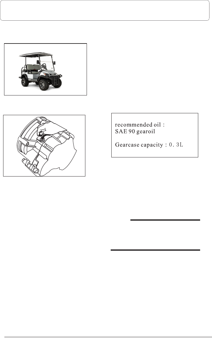
2. Link the cables as the picture
Check the oil level in the gearbox
Gearbox Oil
1. Place the car on a horizontal level
2. Lift the cushion
3. Remove the oil plug
4. Pour in the gear oil slowly until it
reaches the opening
5. It's fine for oil overflowing.
Make it stop when it flows out, alien
materials are forbidden from getting
into the gearbox.
NOTE:
For oil change, please consult your
AdvancedEV dealer or other
qualified mechanic.
Maintenance
Maintenance
19
20
When installing the batteries:
1. Please carefully place the cables and make them down, making sure
the cables not crossover the vent caps.
2. Always remove the negative(-) cable from the motor controller first,
and install it at last.
3. Do not over-tighten the battery nuts, because too much force would
damage the battery case.
2. Link the cables as the picture
Check the oil level in the gearbox
Gearbox Oil
1. Place the car on a horizontal level
2. Lift the cushion
3. Remove the oil plug
4. Pour in the gear oil slowly until it
reaches the opening
5. It's fine for oil overflowing.
Make it stop when it flows out, alien
materials are forbidden from getting
into the gearbox.
NOTE:
For oil change, please consult your
AdvancedEV dealer or other
qualified mechanic.
Maintenance
Maintenance

21
22
Brake Pedal Travel Adjustment:
2-5mm
CAUTION
Tire Replacement
1. Take out the wheel nuts, after the car is
totally still. Anything will be fine to
prevent it moving.
2. Elevate the car with a jack and take out
the tire and the screw bolt.
3. Use the steps above conversely, when
installing the tire.
Be sure the main switch be in the"off"
position, before you check the wheel or
braking system.
Brake Adjustment
The brake of this car can be adjusted by
yourself.
Please use your foot to press the braking
pedal, making sure it has been functioning
properly.
Wheel nut tightening torque:
Consult your AdvancedEV dealer
before using the car, if you have any
problem with the brake. Because
serious accident would be caused in
case of brake failure.
Do not loosen the brake cables
because of air leakage, which will
also affect the brake adjustment
and result in braking function.
1. To change the length of the push rod
and thus increase the brake pedal free
travel, firstly loosen the lock nut on the
brake master cylinder push rod, then
carefully turn the push rod in the
counterclockwise direction.
After adjusting the brake padel travel
properly, tighten the screw in time to
prevent it from loosening.
2. The brake pedal free travel can be
adjusted, but not frequently. It is
recommended to adjust the distance
between 2-5mm and increase the
length of the push rod by 1-2mm.
CAUTION
Before adjusting the brake, tread
the brake pedal several times to
adjust the brakes.
Maintenance
Maintenance

23
24
Clean Lube Pedal
Control Area
Check for loose or broken connections
Check bode and chassis, for damage
Check tightness of all bolts, nuts, and screw
Clean tire pressure tread
depth tire surface for damage
Clean Battery tops, for
tightness of hold-down
screws and terminals
Check shoe lining thickness
and rear axle beating play
Check steering knuckle
bushing freeplay / Adjust
wheel alignment
Check wheel not tightness
front wheel bearing play
Check gear box oil level
and leakage
Check for grease leakage;
adjust gear box if
Periodic Maintenance Chart
It is necessary to check periodically for
best performance and safe operation.
Do not fix brake cable too tight as this
will make the brake adjust can't work
perfectly, and therefore lower down the
brake performance.
Before maintenance, make sure that
main switch is off and hand brake on.
Your local dealer or qualified technician
are responsible for it.
Items without a page number reference should be serviced by approved agent or
qualified technician.
This manual doesn't contain these procedures. They are contained in the Service
Manual.
Maintenance
Maintenance

25
26
1. We do free repair service as our standard warranty
2. Please contact us for universal parts, like tire, cushion, which are out of warranty.
3. We will send technicians if there is mass quality problem.
4. Provide long-term after sales service when warranty date is invalid.
Below conditions are not under warranty
1. Do not do as instruction book.
2. Repair car in places we did not appoint.
3. Out of warranty.
4. Used spare part from other manufacturers.
5. Assemble or modify without our permission.
6. Over max capability when using.
7. Caused by some natural disasters like typhoon, flood, earthquake, etc.
Please read the following carefully for your interest and good after sales service
from us.
What is under warranty and valid date
Please read this instruction book carefully after you buy car from us.
We promise to change or repair for material quality or designing problem.
Objects & Content
After the car is delivered from our factory
CHASSIS PREPARATION
1. Verify the air pressure of the tire is
25psi (4kgf/cm3);
2. Clean the outside of the car with
anti-rust oil;
3. Cover the car and store it in a dry and
well-ventilated place.
BATTERY PREPARATION
1. Recharge the batteries and check the
fluid levels at least once a month.
2. Disconnecting cables in case of long
storage.
3. Clean the top of the batteries with
baking soda and water so as to avoid
erosion.
Cleaning products are forbidden to
put into battery cells
CAUTION
NOTE:
Perform the following preparations when
leaving your golf car unused for a long
time:
Turn the main switch key to the "OFF"
position, remove the key, and put it in a
safe place.
WWaarrrraannttyy AAnndd AAfftteerr--SSaallee SSeerrvviiccee
Storage

25
26
1. We do free repair service as our standard warranty
2. Please contact us for universal parts, like tire, cushion, which are out of warranty.
3. We will send technicians if there is mass quality problem.
4. Provide long-term after sales service when warranty date is invalid.
Below conditions are not under warranty
1. Do not do as instruction book.
2. Repair car in places we did not appoint.
3. Out of warranty.
4. Used spare part from other manufacturers.
5. Assemble or modify without our permission.
6. Over max capability when using.
7. Caused by some natural disasters like typhoon, flood, earthquake, etc.
Please read the following carefully for your interest and good after sales service
from us.
What is under warranty and valid date
Please read this instruction book carefully after you buy car from us.
We promise to change or repair for material quality or designing problem.
Objects & Content
After the car is delivered from our factory
CHASSIS PREPARATION
1. Verify the air pressure of the tire is
25psi (4kgf/cm3);
2. Clean the outside of the car with
anti-rust oil;
3. Cover the car and store it in a dry and
well-ventilated place.
BATTERY PREPARATION
1. Recharge the batteries and check the
fluid levels at least once a month.
2. Disconnecting cables in case of long
storage.
3. Clean the top of the batteries with
baking soda and water so as to avoid
erosion.
Cleaning products are forbidden to
put into battery cells
CAUTION
NOTE:
Perform the following preparations when
leaving your golf car unused for a long
time:
Turn the main switch key to the "OFF"
position, remove the key, and put it in a
safe place.
W
W
a
a
r
r
r
r
a
a
n
n
t
t
y
y
A
A
n
n
d
d
A
A
f
f
t
t
e
e
r
r
-
-
S
S
a
a
l
l
e
e
S
S
e
e
r
r
v
v
i
i
c
c
e
e
Storage

Head light/L
Accelerator
Head light/R
Relay
Relay
DC
2
3
1
1
2
2
3
1
1
2
1
2
12
2
1
103218
1
2
combination switch
4
3
2
1
EMB
号讯:AMP P/N 770680-1
端子:AMP P/N 770520
B+
B-
Key switch
Switch F/R
Combination
USB connector
Cigarettle lighter
Fus box
Fasher
Horn
Brake light switch
Buzzer
DC-DC
Encoder
Speed sensor
Sensor
Charger receptacle
Three switch
Rear light/L
Rear light/R
3
2
1
BX2061
27
28
AC Toyota Controller
Wiring Diagram
Valid Warranty
Buyers need to fill warranty card, stamp and send back to us. The warranty
comes into effect upon we receive and confirm.
Kind Statement
Any damage caused by improper action, which does not match instruction
book, we will not accept as warranty.
W
W
a
a
r
r
r
r
a
a
n
n
t
t
y
y
A
A
n
n
d
d
A
A
f
f
t
t
e
e
r
r
-
-
S
S
a
a
l
l
e
e
S
S
e
e
r
r
v
v
i
i
c
c
e
e

Head light/L
Accelerator
Head light/R
Relay
Relay
DC
2
3
1
1
2
2
3
1
1
2
1
2
12
2
1
103218
1
2
combination switch
4
3
2
1
EMB
号讯:AMP P/N 770680-1
端子:AMP P/N 770520
B+
B-
Key switch
Switch F/R
Combination
USB connector
Cigarettle lighter
Fus box
Fasher
Horn
Brake light switch
Buzzer
DC-DC
Encoder
Speed sensor
Sensor
Charger receptacle
Three switch
Rear light/L
Rear light/R
3
2
1
BX2061
27
28
AC Toyota Controller
Wiring Diagram
Valid Warranty
Buyers need to fill warranty card, stamp and send back to us. The warranty
comes into effect upon we receive and confirm.
Kind Statement
Any damage caused by improper action, which does not match instruction
book, we will not accept as warranty.
WWaarrrraannttyy AAnndd AAfftteerr--SSaallee SSeerrvviiccee

29
30
AC Curtis Controller
Anomalies
No
Temperature
anomaly
Internal temperature above 80℃
①
Internal temperature below -20℃
Contator coil short cicuit
Forward and backward switches both ON
KEY O F F→O N
KEY O F F→O N
②
|Phase current value| > 630A
KEY O F F→O N
When stop, current sensor AD average
is beyond 2048±140
Internal temperature sensor values
correctly
Battery voltage above 60V
③
④
⑤
Internal temperature sensor short circuit
or break
KEY O F F→O N
TTHHEE MMAALLFFUUNNCCTTIIOONN TTAABBLLEE OOFF TTOOYYOOTTAA CCOONNTTRROOLLLLEERR ((4488VV))
1
2
3
4
5
1s
0.5s
0.1s
1s
0.5s
0.1s
0.5s
0.1s
1s
0.5s
0.1s
0.5s
0.1s 0.5s
0.1s
②
③
④
⑤
1s
0.5s
0.1s
0.5s
0.1s
0.5s
0.1s
1s
0.5s
0.1s
0.5s
0.1s
0.5s
0.1s
0.5s
0.1s
0.1s 0.5s
0.1s 0.5s
(※)LED Flash Button Details
①
Internal temperature above 75℃
Internal temperature below -15℃
Battery voltage below 36V
Battery voltage below 54V
Battery voltage above 40V
AC Toyota Controller
Preliminary / Confidential
External
connection
anomaly
Current
anomaly
Internal
sensor anomaly
Voltage
sensor anomaly
Exceptional condition Restoration condition LED Flash Button
Wiring Diagram

29
30
AC Curtis Controller
Anomalies
No
Temperature
anomaly
Internal temperature above 80℃
①
Internal temperature below -20℃
Contator coil short cicuit
Forward and backward switches both ON
KEY O F F→O N
KEY O F F→O N
②
|Phase current value| > 630A
KEY O F F→O N
When stop, current sensor AD average
is beyond 2048±140
Internal temperature sensor values
correctly
Battery voltage above 60V
③
④
⑤
Internal temperature sensor short circuit
or break
KEY O F F→O N
T
T
H
H
E
E
M
M
A
A
L
L
F
F
U
U
N
N
C
C
T
T
I
I
O
O
N
N
T
T
A
A
B
B
L
L
E
E
O
O
F
F
T
T
O
O
Y
Y
O
O
T
T
A
A
C
C
O
O
N
N
T
T
R
R
O
O
L
L
L
L
E
E
R
R
(
(
4
4
8
8
V
V
)
)
1
2
3
4
5
1s
0.5s
0.1s
1s
0.5s
0.1s
0.5s
0.1s
1s
0.5s
0.1s
0.5s
0.1s 0.5s
0.1s
②
③
④
⑤
1s
0.5s
0.1s
0.5s
0.1s
0.5s
0.1s
1s
0.5s
0.1s
0.5s
0.1s
0.5s
0.1s
0.5s
0.1s
0.1s 0.5s
0.1s 0.5s
(※)LED Flash Button Details
①
Internal temperature above 75℃
Internal temperature below -15℃
Battery voltage below 36V
Battery voltage below 54V
Battery voltage above 40V
AC Toyota Controller
Preliminary / Confidential
External
connection
anomaly
Current
anomaly
Internal
sensor anomaly
Voltage
sensor anomaly
Exceptional condition Restoration condition LED Flash Button
Wiring Diagram

Red and yellow LED light flash
alternately
31
32
AC Curtis Controller
AC Curtis Controller
Controller fails. It is necessary to read the
fault code value according to the light
flashing.
The fault code consists of two digits.
The fixed order is: first red then yellow.
The flashing of a red light represents the
number of digits.
The flashing yellow light represents the
specific value of the corresponding digit
number.
When the red light flashes once, it means
that the corresponding code digit is ten
digits, and when it flashes twice, it means
the unit digit. For example, the red light
flashes once and the yellow light flashes
three times.
Represents a ten-digit value of 3.
Then the red light flashes twice and the
yellow light flashes once, indicating that the
units digit value is 1.
In this way, the complete fault code is 31.
The LED light can show multiple faults and
read the code values in turn in this way.
Red LED light is always on
Yellow nad red LED light are always on
Yellow LED light flahes
Both LED lights are off
LED display information description
The watchdog is not working, or the
software is not installed.
Re-turn on and off key switch to start.
Reinstall the software if needed.
The controller is in the program loading state
Controller works normally
The controller power is not connected
or the vehicle battery runs out or other
serious failure
Controller Trouble Shooting Process
Controller Trouble Shooting Process

909-938-7721
advancedev.com
