
1/27
Classification: Reference: Date:
EL18-016 NTB18-060 Se
p
tember 4
,
2018
VOLUNTARY SAFETY RECALL CAMPAIGN
MECHANICAL KEY IGNITION SYSTEM
CAMPAIGN ID #:
PC642 or PM828
APPLIED VEHICLES:
2017-2018 Frontier (D40)
2017-2018 Micra (K13)
2017 NV1500, 2500, 3500 (F80)
2017 NV200 (M20)
2017 Sentra (B17)
2017 Taxi
2017-2018 Versa Note (E12)
2017-2018 Versa Sedan (N17)
Check Service COMM or Dealer Business Systems (DBS)
National Service History to confirm campaign eligibility.
INTRODUCTION
Nissan is conducting this voluntary safety recall campaign on the APPLIED VEHICLES
listed above to inspect and, if necessary, replace the ignition switch. This service will be
performed at no charge to the customer for parts or labor.
DENTIFICATION NUMBER
Nissan has assigned identification number PC642 or PM828 to this campaign based on the
model of the vehicle. This number must appear on all communication and documentation of
any nature dealing with this campaign.
DEALER RESPONSIBILITY
It is the dealer’s responsibility to check Service COMM or Dealer Business Systems (DBS)
National Service History for the campaign status on each vehicle falling within the range of
this voluntary safety recall which for any reason enters the service department. This
includes vehicles purchased from private parties or presented by transient (tourist) owners
and vehicles in a dealer’s inventory. Federal law requires that new vehicles in dealer
inventory which are the subject of a safety recall must be corrected prior to sale.
Failure to do so can result in civil penalties by the National Highway Traffic Safety
Administration. While federal law applies only to new vehicles, Nissan strongly
encourages dealers to correct any used vehicles in their inventory before they are retailed.
Nissan Bulletins are intended for use by qualified technicians, not 'do-it-yourselfers'. Qualified technicians are
properly trained individuals who have the equipment, tools, safety instruction, and know-how to do a job
properly and safely. NOTE: If you believe that a described condition may apply to a particular vehicle, DO
NOT assume that it does. See your Nissan dealer to determine if this applies to your vehicle.

2/27 NTB18-060
REPAIR OVERVIEW
Check Service COMM or Dealer Business Systems (DBS)
National Service History for campaign ID # PC642 or PM828 to confirm the
vehicle you are working on requires this campaign.
Record (write down) radio stations and any
other customer settings that will be lost when
the battery is disconnected.
Remove the ignition switch and record ignition
switch lot number.
Perform IGNITION SWITCH INSPECTION on
Page 24.
Good No Good
Replace ignition
switch and
reassemble
vehicle.
Reassemble
vehicle – No
repairs required.

3/27 NTB18-060
Perform steps 1 through 4 on this page, and then go to the specific procedure according to
the TABLE OF CONTENTS, below.
TABLE OF CONTENTS
2017-2018 Frontier............................................................................................. Page 4
2017-2018 Micra................................................................................................ Page 6
2017 NV1500, 2500, 3500................................................................................. Page 11
2017 NV200, Taxi.............................................................................................. Page 13
2017 Sentra........................................................................................................ Page 16
2017-2018 Versa Sedan and Note..................................................................... Page 19
Ignition Switch Inspection................................................................................... Page 24
SERVICE PROCEDURE
CAUTION: Handle interior trim carefully to avoid damage. Work with clean hands and
clean tools to avoid dirt and stains. Use protective covers as needed.
IMPORTANT: Follow all cautions, warnings, and notes in the Electronic Service Manual
(ESM) when working on or near a Supplemental Restraint System (SRS), such as an air
bag or OCS components.
1. Turn the ignition ON, engine OFF.
2. Write down the radio settings.
Presets
1 2 3 4 5 6
AM
FM 1
FM 2
SAT 1
SAT 2
SAT 3
Bass Treble Balance Fade Spd Sen. Vol.
3. Write down setting for other systems that will lose memory when the 12 volt battery is
disconnected.
Refer to the ESM section, PG – Power, Supply & Ground Elements for a listing of
systems that require reset/initialization after reconnecting the 12V battery.
For PDF ESM: Look in the PG section index for ADDITIONAL SERVICE WHEN
REMOVING BATTERY NEGATIVE TERMINAL.
For Web ESM: Navigate to - ELECTRICAL & POWER CONTROL > POWER
SUPPLY, GROUND & CIRCUIT ELEMENTS > BASIC INSPECTION >
INSPECTION AND ADJUSTMENT > ADDITIONAL SERVICE WHEN REMOVING
BATTERY NEGATIVE TERMINAL
This list often includes items such as radio, power windows, clock, sunroof, etc.
4. Turn the ignition OFF.

4/27 NTB18-060
2017-2018 FRONTIER
Figure 1
Figure 2
Figure 3
1. Adjust the driver seat to the most
rearward position.
2. Disconnect both battery cables and
wait at least 3 minutes.
Disconnect negative battery cable
first.
If needed, refer to the Electronic
Service Manual (ESM) section PG -
(Power Supply, Ground, & Circuit
Elements).
3. Look up under the dash, near the
steering column area to locate the
ignition switch.
View as seen when looking up
under the dash, at the steering
column.
Ignition
switch

5/27 NTB18-060
Figure 4
Figure 5
Figure 6
8. Proceed to Page 24 to perform the Ignition Switch Inspection procedure.
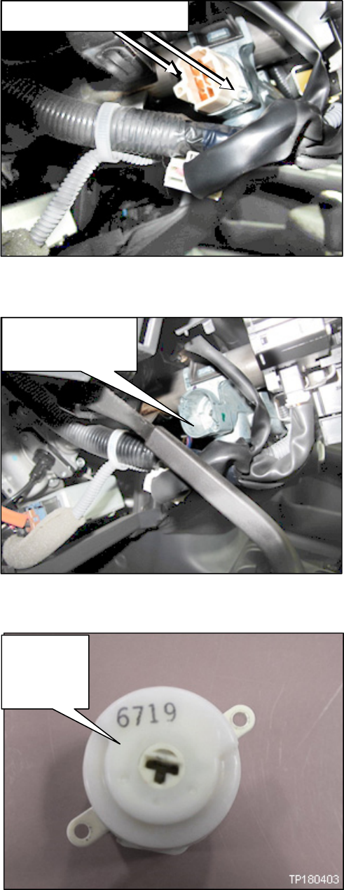
4. Disconnect the ignition switch harness
connector.
Depress the tab on the ignition
switch harness connector to release
it from the ignition switch.
5. Remove the (2) ignition switch screws.
6. Remove the ignition switch from the
steering column.
7. Record the lot number located on the
back side of the ignition switch.
Lot Number________________
NOTE: Lot number shown in Figure 6
is an example. Your lot number may be
different.
Ignition
switch
Tab
Lot
number
example
Ignition
switch
harness
connector
TP180442
TP180443
Ignition switch screws
Ignition switch

6/27 NTB18-060
2017-2018 MICRA
1. Disconnect both battery cables and wait at least (3) minutes.
Disconnect negative battery cable first.
If needed, refer to the Electronic Service Manual (ESM) section PG - (Power
Supply, Ground, & Circuit Elements).
Figure 7
Figure 8
2. Use a plastic trim tool to remove the
instrument side finisher (LH).
3. Remove the data link connector from
instrument lower panel (LH).
Data link connector is held on with
(1) screw.
Instrument side finisher (LH)
Data link connector screw
TP180405

7/27 NTB18-060
Figure 9
Figure 10
Figure 11
4. Remove the hood lock/fuel filler door
release lever assembly bolts.
Hood lock/fuel filler door release
lever assembly is held on with (2)
bolts.
Pull the hood lock/fuel filler door
release lever assembly rearward to
remove.
5. Remove the instrument lower panel
(LH).
Release instrument lower panel
(LH) pawls and metal clips using a
plastic trim tool.
CAUTION: Release pawls and
metal clips slowly so they are not
damaged.
6. Disconnect the harness connectors
from the back side of the instrument
lower panel (LH).
Figure 11 shows connectors already
disconnected.
Hood
lock/fu
el filler
Harness connectors
Harness connector locations
TP180406
TP180407
TP180408
Hood
lock/fuel
filler door
release
bolts
Instrument lower panel (LH)

8/27 NTB18-060
7. Remove the steering column cover screws.
Rotate steering wheel to access steering column cover screws.
Figure 12 Figure 13
Figure 14
8. Remove the steering column covers:
a. Tilt the steering column to the
lowest position.
b. Pull the steering column upper
cover (1) upward to release
steering column upper cover pawls
from the steering column lower
cover (2).
= Pawls
Harness connectors
Steering column cover screws
TP180409
TP180410
TP180411

9/27 NTB18-060
Figure 15
Figure 16
9. Disconnect the ignition switch harness
connector.
Depress the tab on the ignition
switch harness connector to
release it from the ignition switch.
Ignition switch harness connector
Ignition
switch
harness
connecto
r
Tab
TP180412
TP180413
10/27 NTB18-060
Figure 17
Figure 18
Figure 19
13. Proceed to Page 24 to perform the Ignition Switch Inspection procedure.
10. Remove the (2) ignition switch screws.
11. Remove the ignition switch from the
steering column.
Figure 18 shows ignition switch
already removed.
12. Record the lot number located on the
back side of the ignition switch.
Lot Number________________
NOTE: Lot number shown in Figure 19
is an example. Your lot number may be
different.
Lot
number
example
Ignition switch
location
TP180414
TP180415
Ignition switch screws

11/27 NTB18-060
2017 NV1500, 2500, 3500
Figure 20
Figure 21
Figure 22
1. Adjust the driver seat to the most
rearward position.
2. Disconnect both battery cables and
wait at least 3 minutes.
Disconnect negative battery cable
first.
If needed, refer to the Electronic
Service Manual (ESM) section PG -
(Power Supply, Ground, & Circuit
Elements).
3. Look up under the dash, near the
steering column area to locate the
ignition switch.
View as seen when looking up
under the dash, at the ignition
switch.
Ignition
switch
TP180416
TP180417
TP180418

12/27 NTB18-060
Figure 23
Figure 24
Figure 25
8. Proceed to Page 24 to perform the Ignition Switch Inspection procedure.
4. Disconnect the ignition switch harness
connector.
Depress the tab on the ignition
switch harness connector to release
it from the ignition switch.
5. Remove the (2) ignition switch screws.
6. Remove the ignition switch from the
steering column.
7. Record the lot number located on the
back side of the ignition switch.
Lot Number________________
NOTE: Lot number shown in Figure 25
is an exam
ple. Your lot number may be
different.
Ignition
switch
Tab
Lot
number
example
Ignition
switch
harness
connector
TP180419
TP180420
Ignition switch screws

13/27 NTB18-060
2017 NV200 and 2017 TAXI
Figure 26
3. Remove the steering column cover screws.
Rotate the steering wheel to access steering column cover screws.
Figure 27 Figure 28
Figure 29
1. Disconnect both battery cables and
wait at least 3 minutes.
Disconnect negative battery cable
first.
If needed, refer to the Electronic
Service Manual (ESM) section PG -
(Power Supply, Ground, & Circuit
Elements).
2. Remove the ignition switch bezel.
4. Remove the steering column covers:
a. Tilt the steering column to the
lowest position.
b. Pull the steering column upper
cover (1) upward to release
steering column upper cover pawls
from the steering column lower
cover (2).
= Pawls
Harness connectors
Steering column cover screws
TP180421
TP180422
TP180423
TP180411
Ignition
switch
bezel

14/27 NTB18-060
Figure 30
Figure 31
5. Disconnect the ignition switch harness
connector.
Depress the tab on the ignition
switch harness connector to
release it from the ignition switch.
6. Remove the (2) ignition switch screws.
Ignition switch harness connector
Tab
TP180424
TP180425
Ignition switch screws

15/27 NTB18-060
Figure 32
Figure 33
9. Proceed to Page 24 to perform the Ignition Switch Inspection procedure.
7. Remove the ignition switch.
Figure 32 shows ignition switch
already removed.
8. Record the lot number located on the
back side of the ignition switch.
Lot Number________________
NOTE: Lot number shown in Figure 33
is an example. Your lot number may be
different.
Lot
number
example
Ignition switch
location
TP180426

16/27 NTB18-060
2017 SENTRA
1. Disconnect both battery cables and wait at least 3 minutes.
Disconnect negative battery cable first.
If needed, refer to the Electronic Service Manual (ESM) section PG - (Power
Supply, Ground, & Circuit Elements).
2. Remove the steering column cover screws.
Rotate the steering wheel to access steering column cover screws.
Figure 34 Figure 35
Figure 36
3. Remove the steering column covers:
a. Tilt the steering column to the
lowest position.
b. Pull the steering column upper
cover (1) upward to release
steering column upper cover pawls
from the steering column lower
cover (2).
= Pawls
Steering column
cover screw
Steering
column cover
screw
TP180427
TP180428
TP180411

17/27 NTB18-060
Figure 37
Figure 38
4. Disconnect the ignition switch harness
connector.
Depress the tab on the ignition
switch harness connector to
release it from the ignition switch.
5. Remove the (2) ignition switch screws.
Ignition switch
harness connector
Tab
TP180429
TP180430
Ignition switch screws

18/27 NTB18-060
Figure 39
Figure 40
8. Proceed to Page 24 to perform the Ignition Switch Inspection procedure.
6. Remove the ignition switch.
Figure 39 shows ignition switch
already removed.
7. Record the lot number located on the
back side of the ignition switch.
Lot Number________________
NOTE: Lot number shown in Figure 40
is an example. Your lot number may be
different.
Lot
number
example
Ignition switch
location
TP180431

19/27 NTB18-060
2017-2018 VERSA SEDAN AND NOTE
Figure 41
Figure 42
Figure 43
1. Disconnect both battery cables and
wait at least 3 minutes.
Disconnect negative battery cable
first.
If needed, refer to the Electronic
Service Manual (ESM) section PG
- (Power Supply, Ground, &
Circuit Elements).
2. Remove the data link connector from
the instrument lower panel (LH).
Data link connector is held on with
(2) screws.
3. Remove the hood lock/fuel filler door
release lever assembly.
Hood lock/fuel filler door release
lever assembly is held on with (2)
bolts.
4. Pull the hood lock/fuel filler door
release lever assembly rearward to
remove.
5. Use a plastic trim tool to remove the
instrument side finisher (LH).
Hood
lock/fu
el filler
Hood
lock/fuel
filler door
release
bolts
Data link
connector
screws
Instrument
side finisher
(LH)
TP180432
TP180406

20/27 NTB18-060
Figure 44
Figure 45
Figure 46
6. Use a plastic trim tool to remove the
instrument lower panel (LH).
: Pawl
: Metal clip
CAUTION: Release the pawls and
metal clips slowly so that they are
not damaged.
7. Disconnect the harness connectors
from the back side of the instrument
lower panel (LH).
Figure 45 shows connectors already
disconnected.
8. Remove the instrument panel lower
support bracket.
Instrument panel lower support
bracket is held on with (4) bolts.
NOTE: For reassembly, torque
bolts to;
8.5 N•m (.86 kg-m, 75 in-lb).
WARNING: There are parts in the
instrument panel area that have sharp
edges. Be careful when handling these
parts.
Harness connectors
Harness connector locations
Lower support bracket screws
TP180434
TP180435
TP180408

21/27 NTB18-060
9. Remove the steering column cover screws.
Rotate the steering wheel to access steering column cover screws.
Figure 47 Figure 48
Figure 49
10. Remove the steering column covers:
a. Tilt the steering column to the
lowest position.
b. Pull the steering column upper
cover (1) upward to release
steering column upper cover pawls
from the steering column lower
cover (2).
= Pawls
Harness connectors
Steering column cover screws
TP180436
TP180437
TP180411

22/27 NTB18-060
Figure 50
Figure 51
Figure 52
11. Disconnect the ignition switch harness
connector.
Depress the tab on the ignition
switch harness connector to
release it from the ignition switch.
12. Remove the (2) ignition switch screws.
Ignition switch harness connector
Ignition
switch
harness
connecto
r
Tab
TP180439
TP180440
Ignition switch screws

23/27 NTB18-060
Figure 53
Figure 54
15. Proceed to Page 24 to perform the Ignition Switch Inspection procedure.
13. Remove the ignition switch from the
steering column.
Figure 53 shows ignition switch
already removed.
14. Record the lot number located on the
back side of the ignition switch.
Lot Number________________
NOTE: Lot number shown in Figure 54
is an example. Your lot number may be
different.
Lot
number
example
Ignition switch
location
TP180441
24/27 NTB18-060
IGNITION SWITCH INSPECTION
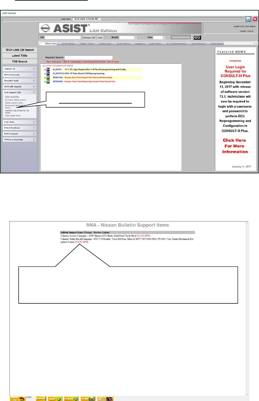
1. Open ASIST.
2. Select the “Tech Support Info” tab on the left side of the ASIST screen.
3. Select “Bulletin Support Items”.
Figure 55
4. Select “Voluntary Safety Recall Campaign – MY17/18 Frontier, Versa SD/Note, Micra &
MY17 NV1500-3500, NV200 + Taxi, Sentra Mechanical Key Ignition System CLICK
HERE…”
Figure 56
“Bulletin Support Items”
Voluntary Safety Recall Campaign – MY17/18 Frontier, Versa
SD/Note, Micra & MY17 NV1500-3500, NV200 + Taxi, Sentra
Mechanical Key Ignition System CLICK HERE…

25/27 NTB18-060
5. Input the number found on the backside of the ignition switch.
6. Select “Check.”
Figure 57
7. If the ignition switch is GOOD as shown in Figure 58 then the ignition switch
DOES NOT need to be replaced.
Reinstall the original ignition switch.
Reinstall all components in the opposite order of removal.
Proceed to Step 9 on Page 26.
Figure 58
In
p
ut number here
XXXX

26/27 NTB18-060
8. If the ignition switch is NO-GOOD as shown in Figure 59, REPLACE the ignition switch.
Replace the ignition switch with the one listed in the PARTS INFORMATION section
of this bulletin.
Reinstall all components in the opposite order of removal.
Figure 59
9. Reset/reinitialize systems as needed.
Refer to the ESM section, PG – Power, Supply & Ground Elements for a listing of
systems that require reset/initialization after reconnecting the 12V battery.
For PDF ESM: Look in the PG section index for ADDITIONAL SERVICE WHEN
REMOVING BATTERY NEGATIVE TERMINAL.
For Web ESM: Navigate to - ELECTRICAL & POWER CONTROL > POWER
SUPPLY, GROUND & CIRCUIT ELEMENTS > BASIC INSPECTION >
INSPECTION AND ADJUSTMENT > ADDITIONAL SERVICE WHEN REMOVING
BATTERY NEGATIVE TERMINAL
This list often includes items such as radio, power windows, clock, sunroof, etc.
XXXX

27/27 NTB18-060
PARTS INFORMATION
DESCRIPTION PART NUMBER QUANTITY
Switch Assy. - Ignition D8G50-0M010 1
CLAIMS INFORMATION
Submit a “CM” line claim using the following claims coding:
CAMPAIGN
(“CM”) ID
DESCRIPTION
OP
CODE
FRT
PC642
2017-2018
Frontier
Inspect ignition switch (No parts
needed)
PC6420 0.5 hrs.
Inspect and replace ignition switch PC6421 0.5 hrs.
2017 NV1500,
2500, 3500
Inspect ignition switch (No parts
needed)
PC6420 0.5 hrs.
Inspect and replace ignition switch PC6421 0.5 hrs.
PM828
2017 NV200
Inspect ignition switch (No parts
needed)
PM8285 0.5 hrs.
Inspect and replace ignition switch PM8280 0.5 hrs.
2017 Sentra
Inspect ignition switch (No parts
needed)
PM8287 0.5 hrs.
Inspect and replace ignition switch PM8282 0.5 hrs.
2017 Taxi
Inspect ignition switch (No parts
needed)
PM8285 0.5 hrs.
Inspect and replace ignition switch PM8280 0.5 hrs.
2017-2018 Versa
Note
Inspect ignition switch (No parts
needed)
PM8288 0.7 hrs.
Inspect and replace ignition switch PM8283 0.7 hrs.
2017-2018 Versa
Sedan
Inspect ignition switch (No parts
needed)
PM8286 0.7 hrs.
Inspect and replace ignition switch PM8281 0.7 hrs.
2017-2018 Micra
Inspect ignition switch (No parts
needed)
PM8289 0.6 hrs.
Inspect and replace ignition switch PM8284 0.6 hrs.
