© 2003 AMS Neve plc own the copyright of all
information and drawings contained in this manual which
are not to be copied or reproduced by any means or
disclosed in part or whole to any third party without
written permission.
As part of our policy of continual product improvement,
we reserve the right to alter specifications without notice
but with due regard to all current legislation.
Disclaimer: The information in this manual has been
carefully checked and is believed to be accurate at the
time of publication. However, no responsibilty is taken by
us for inaccuracies, errors or omissions nor any liability
assumed for any loss or damage resulting either directly or
indirectly from use of the information contained within it.
AMS NEVE INC., NEW YORK
TEL: +1 (212) 965 1400 • FAX: +1 (212) 965 9306
AMS NEVE INC., HOLLYWOOD
TEL: +1 (818) 753 8789 • FAX: +1 (818) 623 4839
AMS NEVE PLC • BILLINGTON ROAD • BURNLEY
LANCS BB11 5UB • ENGLAND
TELEPHONE: +44 (0) 1282 457011 • FAX: +44 (0) 1282 417282
HEAD OFFICE
TELEPHONE: +44 (0) 20 7916 2828 • FAX: +44 (0) 20 7916 2827
LONDON OFFICE
NORTH AMERICAN OFFICES
e-mail: [email protected]
http://www.ams-neve.com
88R
Product Profile
Issue 3

Contents
Introduction..................................3
Design Features .....................................3
Technology ........................................4
Console Layout .....................................5
Architecture .................................7
Main Mix Busses .....................................9
Monitoring .......................................10
Solo Modes .......................................12
Talkback ........................................12
Overdub System ....................................12
Remote Mic Amps ..............................13
Remote Microphone Amplifier Control Software .....................14
Module Descriptions.............................15
Channel Module ....................................15
Monitor and Facilities Section..............................21
Meters .........................................31
TFT Screen .......................................34
Encore Automation .............................35
Snapshots........................................38
Encore Global Master Automation Panel ........................41
Encore Global Master Events Panel ...........................42
Dynamic Automation ..................................43
Recall..........................................44
Machine Control ....................................45
Issue 3 88R Product Profile
Page i
Physical Information .............................47
Console Data ......................................47
Rack Data .......................................47
Power Supply Units ...................................47
Performance Specifications .........................49
Remote Mic Amps Specifications ............................50
Page ii
88R Product Profile Issue 3

Issue 3 88R Product Profile
Page 1
Page 2
88R Product Profile Issue 3

Introduction
The 88R embodies the Neve tradition of being simply the best tool for the job. Designed by engineers
who have crafted many of the Neve analogue consoles over the last three decades, the 88R offers the
classic Neve sound in a full surround format. High quality analogue circuitry is combined with practical
ergonomics and state-of-the-art automation in a console that is ideally suited for music recording and
mixing as well as scoring for TV, DVD and film.
The 88R is supplied with the Encore automation system as standard. Encore brings the best of Flying
Faders for music together with the Logic automation system for post-production, creating the ultimate
music and music-for-picture automation system.
Design Features
·
In-line architecture
·
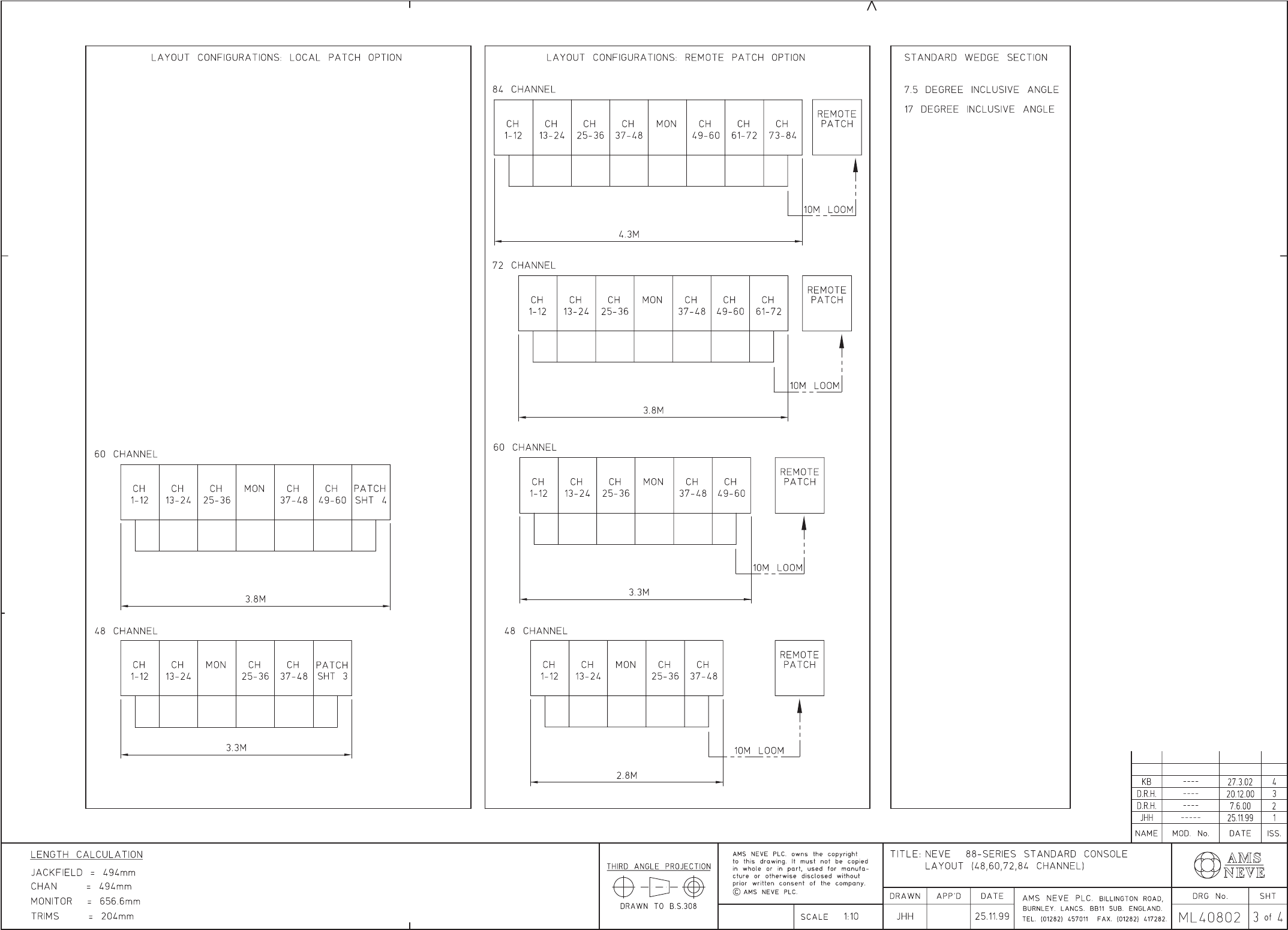
48, 60, 72 and 96 channel frame sizes
·
Straight and angled frames
· Integral or remote patch
· Mic/line or line/line input modules
· 48 track mix busses
· 5 stereo and 1 LCR main mix busses
· Splittable main and aux busses permitting film-style stems
· Stereo and 5.1/LCRS surround monitoring as standard
· Optional monitoring expansion to 7.1 and other 8 way formats
·
LCR panning with selectable divergence
·
Stereo or LCR SOLO
·
Integral or remote microphone amplifiers
·
8 auxiliaries, any pair of which can be made stereo
·
Full dynamics in every channel
·
Neve 4 band Formant EQ
·
Overdub facility inc track arming from each channel
·
Pre-fader direct input for minimal signal path
·
Encore Automation
·
Encore Recall
·
Automated panning optional
·
Automated mini-fader
·
Automated aux send on/off
Issue 3 88R Product Profile
Page 3
·
Integrated multi-machine transport control
·
Full multitrack, surround mix, stems and aux metering
·
VU, PPM and flying spot metering
·
No VCAs in signal path and a passive monitor volume control
·
Optional Joysticks Module
·
Redundant PSU option
·
Choice of 1081 or Air Monserrat style remote mic amps
Technology
The 88R is a completely new electronic and mechanical design. Though based on classic Neve attention
to audio quality, ergonomics and mechanical detail, the 88R takes advantage of the latest analogue
technology.
·
All busses are balanced, Including auxiliary and solo busses, reducing crosstalk and noise.
· Neve high performance microphone amplifier design.
· High resolution PPM/VU LED bargraph meters with programmable bright-up and peak hold
modes.
· High quality, polarised and non-polarised de-coupling capacitors that don’t dry out.
· All switches use LED illumination, eliminating the maintenance task of replacing filament bulbs.
· As standard, all switches are silver-plated giving a long-lasting, clean switching life. Gold-plated
switches are optional.
·
All potentiometers use a conductive plastic track with gold plated wipers, giving super-smooth,
silent operation.
·
All channel modules and fader modules are hot-pluggable, with the power supply 0v wiring for
each module going direct to the bus bars, enhancing LF performance and improving cross-talk.
·
High performance output stages deliver +27dBu distortion free into 600 Ohms.
·
Traditional, high quality mechanical frame, with rigid, well protected channel modules.
·
New high performance microphone amplifier design in the channel module.
Page 4
88R Product Profile Issue 3

Console Layout
Issue 3 88R Product Profile
Page 5
Channel
Meter
Section
Channel
Meter
Section
Output
Meter
Section
Encore
Screen
Aux
Meter
Section
Channel Module
Section
Channel Modul
e
Section
Channel Fader
Section
Channel Fader
Section
Monitor & Facilities
Section
Monitor & Facilities
Fader Section
Encore Global Master
Automation Section
Encore Global Master
Events Section
MCS & Dynamic
Automation Section
Trackball
Reassign Matrix
Section
Limiter
Compressors
Page 6
88R Product Profile Issue 3

Architecture
The 88R uses a conventional in-line recording console architecture extended to address the evolving
needs of the 21st century studio, in particular those of surround sound production. Users of the Neve
V-Series and other high-end analogue consoles will immediately be at home with the control surface.
Using centrally located master switches the signal flow can be optimised for the task in hand at the press
of a button. Local mode buttons on each channel strip give additional flexibility.
Issue 3 88R Product Profile
Page 7
Record mode: - Shows the basic 88R signal flow in Record mode. The mic inputs are on the
large faders, routing to the multitrack busses. The tape return is on the small fader, routing to
the main mix busses.
Mixdown mode: - Switches the tape returns to the channel path which is routed to the main
mix busses. The monitor path can be used for effects returns etc. but can also be routed to
the multitrack busses for use as additional aux sends. Both the small fader and large fader have
moving fader automation which is associated with the path, not the physical fader. This means
that it is possible to swap faders without losing the mix.

The master switches can operate across the whole console, or independently for the left and right sides
of the console. This feature can be used (for example) to easily configure the 88R as a split monitoring
console – mixing on monitors to the left and recording through channels to the right.
Independently of the mode, the signal paths on the large and small fader path can be swapped over,
either locally or globally. Traditionally it was useful to record through the small faders with the
monitors on the automated large faders to get a rough mix in place whilst recording. With both small
and large faders automated on the 88R, the operator is free to lay out recording channels and monitors
as he wishes.
Page 8
88R Product Profile Issue 3
Broadcast mode: - The monitor path source is taken from the channel path, pre fader. This
allows EQ and dynamics to be preserved with level optimised for tape. Alternatively the
CH/OP switch sends a post fade signal to the multitrack, so that mix levels are also recorded.
Main Mix Busses
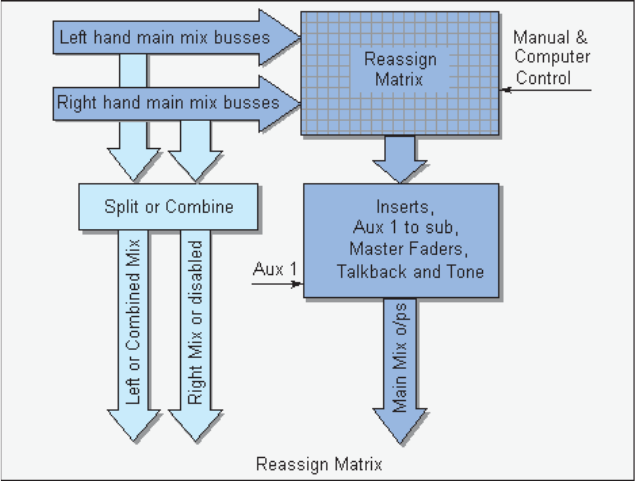
Both the channel and monitor paths can route to the main output mix busses via pan pots that generate
simultaneous stereo and LCR pan laws. There are five stereo busses and one LCR bus, all re-assignable.
Available as an option, using switches on the re-assign panel, stereo busses 1&2 can be combined to
create a second LCR bus. (This may be useful if mixing for Dolby EFX cinema format that uses both
LCR front and LCR rear speakers, or just for creating alternate front mixes).
The mix busses from the left and right side of the console can be combined into a single multi-format
console output, or they can be can be split, allowing independent left and right side console outputs.
The mix busses also go to a computer assisted re-assign system that allows the operator to choose the
main console output format .
The outputs of the re-assign matrix are the console’s main mix outputs and these are available on the
monitoring system. The computer assistance makes it quick and easy to create and recall different mix
formats on the main mix output. The computer provides snapshot and macro facilities, but is not
essential to the operation – the matrix can also be fully controlled manually.
The standard 88R Series main output is six signals wide, suitable for formats up to 6.1 (inc LFE on aux 1.
Fitting the optional scoring panel expands this to 8 main outputs, for 7.1 format mixing.
The ‘Aux 1 to Sub’ facility allows auxiliary 1 to be used to create the LFE (Low Frequency Extension, or
sub-woofer) mix. The aux 1 output is re-introduced to the console via a normalised jack point before
the master fader in a 5.1 mix. This allows complete control of the LFE mix. There is also an insert
provision on the main mix output for an external filter, or low frequency synthesizer.
The re-assign panel has trim controls for the left and right mix bus outputs, the main mix outputs are
controlled by the master faders. Also on the re-assign panel are buttons that set the overall mode of the
console for stereo, 7.1 (requires scoring panel option), 5.1 or 4-TRK (LCRS).
Issue 3 88R Product Profile
Page 9

Monitoring
The 88R comes with comprehensive surround monitoring support for LCRS and 5.1 formats as
standard. This can be extended to full support, including PEC/direct switching and monitoring for
8-way formats by fitting the optional, industry standard Scoring Panel.
The monitoring system incorporates a 6 signal-wide passive volume control, of which up to 6 (5.1)
signals are used on the standard console. An in/ext switch toggles the monitoring between preset
internal and external selectors.
The source selectors can either be interlocked, or put into mix mode. In mix mode the internal and
external selector outputs can be mixed (allowing “in context” monitoring) and any combination of
external sources can be mixed (allowing the monitoring of multiple stems), but a logical degree of
interlocking is kept, eg between auxes, to simplify selection.
The monitoring system supports up to 4, patchable, external 8-track recorders (or one multitrack
recorder, with the tracks arranged as 4 stems). A single pair of Group/Tape switches control
monitoring of track sends (mix output) or track returns. In addition there are patchable facilities for
three 6-way and 9 stereo external inputs.
There is provision for a switchable 6-way insert after the int/ext selector and before the mono & AFL
systems, eg for a Dolby encoder/decoder. There is a separate switch (STEREO COMP) for monitoring
the LtRt output of the encoder when in 4T mode (LCRS).
When the monitoring is switched to mono there is also provision for an Academy filter to be inserted.
The mono signal is a mix of left and right appearing on both left and right speakers when the console is
Page 10
88R Product Profile Issue 3
switched to stereo mode, but is a mix of the whole surround signal that appears on just the centre
speaker when any of the surround modes is selected.
There is provision for 3 sets of front speakers, with independent level trims for the small and mini
speakers. When the large speakers are selected, Return Talkback is routed to the mini and small
speakers. Double clicking the Large speaker selector switch will lock the surround speakers on,
allowing them to be used in conjunction with the mini and small speakers. A headphone output with
level control is also fitted.
As can be seen from the panel layout, there is a full set of monitoring controls, including independent
speaker cuts and solos, L/R balance, AFL/PFL level etc.
Issue 3 88R Product Profile
Page 11
Solo Modes
The 88R has three solo modes: AFL /PFL (using Chan safe and/or Mon safe), and destructive SOLO.
The modes are selected centrally, but destructive solo can be inhibited by linking the system to the tape
machines’ record tallies: a safe mode is then selected on the channels when the multitrack is in record,
or on the monitors when the 4T (stereo or surround) tape machine is in record.
The AFL system is normally LCR with the option of switching left and right AFL to the surround
speakers. The AFL system also a features a mixed solo mode, where the soloed signal (AFL or PFL) can
be balanced against the monitor source on a control that has full monitor and no solo at one end and full
solo and no monitor at the other.
Talkback
The 88R has support for engineer’s talkback, producer’s talkback, 2 return talkback inputs and slate.
There is routing for the engineer and producers’ talkback to cues, foldback, studio loudspeakers, and
switched and non-switched dedicated outputs. Auto TB will ensure that the cue outputs will always get
talkback when the tape machine isn’t playing or recording, so that the artists don’t feel cut off from the
control room between takes. There are full red-light with record and rehearse states, and control
room dim facilities linked into the talkback system.
Overdub System
The 88R’s overdub system differs from previous Neve consoles’, reflecting input from many users. The
overdub system controls what is heard on the artists’ headphones, on the control room speakers and
also controls the track arming of the multitrack recorder. It is affected by the console central status,
cues and multitrack monitor controls.
Page 12
88R Product Profile Issue 3
Remote Mic Amps
Remote mic amps allow the engineer to bring fragile mic level signals to line level as close to the
microphone as possible, optimising audio acquisition. The 88R remote system offers the choice of two
classic 70’s designs: the 1081 and the circuit designed for the renowned Air Monserrat consoles. Both
of these modules use modern construction techniques, but rely on the same component types as the
original amps to faithfully recreate their sound. Switches have been replaced with relays, but the
transformers and discrete op-amps of the 1081 and the tantalum capacitors of the Air Monserrat
console are still there. Although these designs are well known for their sound quality, they are also
technically excellent with low noise and distortion. The two module types have the same functionality
and control system, the choice of which modules to fit is down to personal preference.
Each 88R mic amp rack will take up to 12 modules in any combination and up to 16 racks can be
controlled from the console via Encore. The line level signals from the remote rack are brought to the
line level inputs of channel modules via the patch. The Encore based software allows any module to be
controlled from any console channel, giving freedom in how the console is laid out.
The mic amps can also be fully controlled from their front panels when not assigned to a console
channel. In this mode the display shows the gain of the amp in dB. When the modules are controlled
from the console, the display shows which channel is controlling the module and the gain can be
interrogated by using the INT button. If control from the Encore computer is removed, control returns
to local front panel control.
Issue 3 88R Product Profile
Page 13
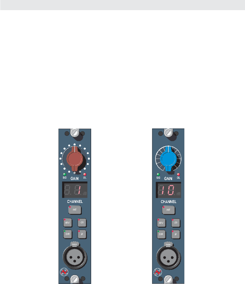
The 88R remote mic amp
based on the original 1081
microphone amplifier and
identified by the red knob
The 88R remote mic amp
based on the Air Monserrat
microphone amplifier and
identified by the blue knob

Remote Microphone Amplifier Control Software
The picture above is of Encore's remote mic amps' control screen showing three attached racks and
rack 1's control settings. Rack 1 is shown fitted with four 1081 modules and two "Air Monserrat"
modules. The modules can be fully controlled from this screen, or using the Channel selector they can
be assigned to 88R channel strips for control through real knobs and switches. The Load and Save
buttons launch standard Windows dialogues for saving and recalling snapshots of the mic amp settings.
Recalling a snapshot for mic amps not under control of a channel module will automatically reset the
mic amp settings to the stored values. Modules that are assigned to 88R channels will also be indirectly
stored and recalled by Encore's console-wide Recall system.
The Setup utility allows the communications between Encore and microphone amplifiers to be tested.
Page 14
88R Product Profile Issue 3

Module Descriptions
Channel Module
Input and Multitrack Output
There are two versions of the channel module, one with an integral microphone
amplifier, and one with dual line level inputs that will support an optional remote
microphone amplifier. Apart from the input section, both versions have identical
facilities.
At the top of the module there are the routing buttons for the 48 multitrack
busses, the 5 stereo and the main LCR bus. The switchable pan control
automatically delivers an L-R pan law to stereo busses and an LCR pan to LCR
busses.
The narrow button changes the width or size of the panned source within the
stereo picture from standard to more of a point source.
The multitrack routing is fed from either the channel path or the monitor path,
depending on the mode of the channel. When recording, the multitrack routing
comes from the channel path, but when mixing the source is normally the monitor
path, allowing the busses to be used as additional auxiliary sends. MTK switches in
the auxiliary send section also allow the aux sends to be diverted to multitrack
busses during mixdown.
Below the routing section, the input section allows mic or line level inputs to be
selected. In the case of a dual line input module, there are two LEDs to indicate
whether the LINE A or LINE B input is selected. Both modules have a mic input
trim control, in the case of the dual line input module this is for the optional remote
mic amplifier.
The GRP group switch allows the channel input to be switched to the multitrack
bus output corresponding to the channel number. For example if several channels
are routed to multitrack bus 6, then pressing GRP on channel 6 will make channel 6 the group master
for these channels.
Below the input section are switchable high and low pass filters.
Issue 3 88R Product Profile
Page 15
M
T
K
1/25 2/26
3/27 4/28
5/29 6/30
7/31 8/32
9/33 10/34
11/35 12/36
13/37 14/38
15/39 16/40
17/41 18/42
19/43 20/44
21/45 22/46
23/47 24/48
1-24
25-48
1-2
3-4
5-6
7-8
9-10
LCR
NAR
PAN
C
LR
gain
C/O
Æ
GRP
-20
LINE
10
-10
0
pull
ph
OFF
MIC
30
20
40
50
70
kHz
7.5
18
13
10
9
8
315
31.5
50
80150
240
Hz
pull
FILT

Dynamics
Full limiter/compressor and gate/expander facilities are available, each of which
can be individually switched in or out of circuit.
The compressor has soft knee characteristics as standard with hard knee available
at the pull of a button.
The gate/expander has rotary controls for a 60dB gate range, a 70dB threshold
range, release from 10ms to 3s, switchable attack time 500ms/50ms and variable
hysteresis.
Hysteresis makes the threshold level different for signals which are rising or falling
in level and allows precise triggering on the wanted signal while still allowing the
correct amount of signal ‘tail’ through.
The expander has a 2:1 expansion ratio. Switched controls are provided for an
external key input and for inserting the EQ into the side-chain. The external key input is accessed from
the patchbay.
The limiter/compressor has rotary controls for release times from 10ms to 3s, a 50dB threshold range,
a ratio of 1:1 to limiting and up to 30dB of gain make-up.
Attack time is program dependent with a switch for fast impulse response ranging from 4ms to 1.2 ms.
The Release control incorporates a switch for automatic programme dependent release.
Anti pumping and breathing circuitry allows the unit to operate on the source musically whilst retaining
absolute control over the dynamic range.
Page 16
88R Product Profile Issue 3
KEY
SC-EQ
L/C
GATE
EXP
HYST
THR
25
20
15
10
5
0
6
12
18
24
30
GAIN
THR
15
7
0
-10
-17
-25
-10
20
14
8
2
-4
pull
-40
20
30
50
60
0
10
pull
FAST
RGE
RAT
lim
3
5
2
pull
FAST
0.2
3s
REL
pull
INV
.01
0.2
3s
REL
.01
AUTO
pull
-20
1
pull
HN
Auxiliary Sends
The eight auxiliary sends can be configured as eight mono sends with either the
channel or monitor path as the signal source.
Each pair of sends can be switched to operate as a stereo aux with level and pan
controls.
Operationally, the pre-fade auxiliaries are usually used to send signals to the artists
in the studio in tracklaying mode and to effects in mixdown mode. The channel
pick-off point in these two modes is arranged so that when tracklaying the signal is
taken pre-cut to enable cut solos to be performed in the control room and still
retain cue sends. In Mixdown mode the signal is taken post-cut so that the effects
send is cut with the source.
In Mixdown mode the multitrack returns are routed to the stereo buses via the
large fader and the small fader output is routed to the multitrack routing matrix -
allowing as many as 48 fully mixable extra auxiliary sends. Alternatively the aux
section MTK buttons can be used to divert one or more of the auxes to the
multitrack busses with the advantage that they have independent level control over
the contributions.
Issue 3 88R Product Profile
Page 17
PRE
MTK
PRE
MTK
5-6
7-8
PRE
MTK
PRE
MTK
PRE
MTK
PRE
MTK
1-2
3-4
PRE
MTK
PRE
MTK
PAN
8
ON
ON
ST
PAN
6
ON
ON
5
ON
4
ON
3
ST
PAN
PAN
2
ON
ON
1
7

EQ and Inserts
Inserts can be positioned in either the channel or monitor path independently of
the equaliser. Pre-equaliser and pre-dynamics configuration is also possible.
Formant Spectrum Equalisers
The unique sound of AMS Neve equalisers is the result of years of research and
extensive studio experience.
The equaliser provides 4-band parametric equalisation, with overlapping
frequency ranges.
HF 1.5kHz - 18kHz
M2 0.8kHz - 8.7kHz
M1 120Hz - 2kHz
LF 33Hz - 440Hz
The two mid-bands have variable controls for Q (from 0.4 to 10), gain (20dB cut
and boost) and frequency.
The high and low frequency EQ controls provide variable gain (20dB cut and boost) and frequency
controls with switchable Q (either 0.7 or 2) and a peak or shelf characteristic.
The equaliser section can be switched before or after the dynamics section.
Page 18
88R Product Profile Issue 3
PREQ
INS
PRE-
DYN
HI-Q
HI-Q
EQ
18
1.5
13
8
5.3
3.2
kHz
9.0
0.8
1.4
2.4
3.7
6.0
kHz
Q
Q
2k
1.4
120
330
570
940
Hz
440
300
Hz
200
120
73
33

Faders Section
Track Send
The track level trim allows the multitrack bus output level for the bus
corresponding to the channel number to be adjusted between -10dB and +10dB.
The channel signal can be routed directly to the corresponding track send,
bypassing the multitrack routing matrix. In this mode, signals from other channels
cannot be routed to this track send.
Small fader
The small fader uses a Penny and Giles conductive plastic moving fader and is
automated in the same way as the large fader. The small fader is normally in the
monitor path, but can be swapped with the large fader.
Either the channel path or the monitor path may be feeding the multitrack routing
at the top of the channel strip depending on the global status (record/mixdown)
and the local C/O switch. The TO MTK LED indicates when it is the monitor path.
The CH/OP button allows the input to the monitor path to come from the channel
path output allowing the small fader to be used an additional aux send to the
multitrack busses during mixdown.
The SWAP button reverses the roles of the small and large faders.
Automation that was written on the small fader gets transferred to the large fader
and vice versa. i.e. the automation stays with the path, not the fader.
The monitor path selectors assign the module’s dynamics, insertion, equaliser,
filters and auxiliaries to the monitor signal path.
The RET switch makes the path safe from solo mutes, allowing it to be used as an
effects return input.
The console has a sophisticated monitoring system allowing monitoring freedom in the control room
while the correct cue sends are retained. The system uses the GRP/TAPE and OD switches in
conjunction with master monitor selection to achieve this. The OD (overdub) switch also allows the
multitrack tape machine to be record armed/punched in from the channel strip.
Mode & Sel
Are used to set the automation modes for the channel switches.
Issue 3 88R Product Profile
Page 19
DIR
C/O
SWAP
CH.OP
DYN
INS
EQ
FILT
7-8
5-6
3-4
1-2
TAPE
GRP
O/D
TRACK
TO MTK
M
O
D
E
M
O
N
I
T
O
R
P
A
T
H
A
U
X
5
0
5
10
20
30
40
10
1-2
3-4
5-6
7-8
9-10
LCR
NAR
PAN
SOLO
CUT
SF
C
L
R
AB
RET
CUT
SOLO
MODE
SEL
R
E
C

Large Fader Section
At the bottom of the channel strip are the routing buttons for the main mix busses.
The pan control creates both LCR and L-R pans for the different bus types. As well
as an on/off switch, the pan control can be set to give a the signal a NARROW width
in the LCR field.
The channel path can be included in one of two cut groups, A and B, which have
master controls in the centre section.
Fader Module
The large fader module has automation controls for the both the large fader and
small fader, and both mute buttons. The automated mute button for the small
fader is also on this module.
Page 20
88R Product Profile Issue 3
1-2
3-4
5-6
7-8
9-10
LCR
NAR
PAN
SOLO
CUT
SF
C
L
R
AB
ALL
SEL
SMALL
FADER
MUTE
MODE
SF
MUTE
LF
MUTE
MUTE
MODE
GLIDE
REC
PLAY
TRIM
10
5
0
5
10
20
30
40
ISOLATE

Monitor and Facilities Section
Oscillator and Signal Threshold
The Signal threshold is the level at which the signal indicators in the meter bridge
come on. This indicator can either be used as a signal present or a signal overload
indicator depending on the level set.
The 7 frequency oscillator is also available on the patch field, independently of the
slate oscillator. Pink noise, or other external sources can also be patched in for
routing to the various outputs.
Issue 3 88R Product Profile
Page 21
+26db
+20
+8+6
+4
SIG PRES
SIGNAL LED
THRESHOLD
SLATE
CAL
FREQUENCY
100
OFFOFF
40Hz 15k
10k
4k
400
1k
LEVEL
SLATE
TONE
MTK
MIX
8T
4T
OSC

Auxiliary Master Section
There two alternative auxiliary master panels. The single panel provides output controls for the 8
console-wide busses. Each pair of auxiliary sends can be configured as two mono sends with
independent level controls, or as one stereo send with a level and balance control.
The split aux panel allows independent outputs for the left and right side of the console, or the busses
can be combined across the console on an individual basis.
Page 22
88R Product Profile Issue 3
BAL
8
7
ON
ON
BAL
6
5
ON
ON
BAL
4
3
ON
ON
BAL
2
1
ON
ON
7-85-6
ST
3-41-2
ST
AUX MASTER
+10
sub
BAL
8
7
ON
ON
BAL
6
5
ON
ON
BAL
4
3
ON
ON
BAL
2
1
ON
ON
7-85-6
ST
3-41-2
ST
AUX MASTER
BAL
8
7
ON
ON
BAL
6
5
ON
ON
BAL
4
3
ON
ON
BAL
2
1
ON
ON
7-85-6
ST
3-41-2
ST
BAL
8
7
ON
ON
BAL
6
5
ON
ON
BAL
4
3
ON
ON
BAL
2
1
ON
ON
7-85-6
ST
3-41-2
ST
L.H. AUX R.H. AUX
+10
sub
7
6
5
4
3
2
1
8
7
6
5
4
3
2
1
8
PRE
PRE
PRE
PRE
PRE
PRE
PRE
PRE
PRE PRE
PRE
PRE
PRE
PRE
PRE
PRE
SPLIT
L.H. R.H.

Cue Mix System
There are two alternative cue mix systems – either two stereo cue mix outputs with high and low
frequency shelving, or four stereo mix outputs with a spectrum tilt control.
Each stereo cue mix is made of the auxiliary, control room monitor output, main output or patch-field
sources selected on the buttons at the top of the section.
The 88R channel module, together with the centre section controls, allow the engineer to set up the
pre-fade auxiliaries to provide intelligent mixes for the artist independently of the control room
monitoring. This includes sending a mix of multitrack send and return with automatic level
compensation when the track is dropped into record during an overdub.
Quad Cue Mix Panel
The optional Quad Cue Mix Panel provides 4 stereo or up to 8 single ear mono mixes.
Issue 3 88R Product Profile
Page 23
7 8
5 6
3 4
1 2
5-6 7-8
1-2
3-4
MON PATCH
1-2
3-4
5-6 7-8
82
47
EQ
A
U
X
A
U
X
150
FILTER
EQ
BAL
LR
LEVEL
ON
BAL
CUE 1
CUE 1 MIX
7 8
5 6
3 4
1 2
5-6 7-8
1-2
3-4
MON PATCH
1-2
3-4
5-6 7-8
82
47
EQ
A
U
X
A
U
X
150
FILTER
EQ
BAL
LR
LEVEL
ON
BAL
CUE 2
CUE 2 MIX
7-8
PATCH 1
5-6
PATCH 2
3-4
MIX 1-2
1-2
MIX 3-4
MON
A
U
X
CUE 1 MIX
MONO
DUAL
CUE TO
MON
FLAT
+LF +HF
PATCH 2
LEVEL
ON
LR
BAL
LEVEL
R
L
TB
7-8
PATCH 1
5-6
PATCH 2
3-4
MIX 1-2
1-2
MIX 3-4
MON
A
U
X
CUE 3 MIX
MONO
DUAL
CUE TO
MON
FLAT
+LF +HF
PATCH 2
LEVEL
ON
LR
BAL
LEVEL
R
L
TB
7-8
PATCH 1
5-6
PATCH 2
3-4
MIX 1-2
1-2
MIX 3-4
MON
A
U
X
CUE 2 MIX
MONO
DUAL
CUE TO
MON
FLAT
+LF +HF
PATCH 2
LEVEL
ON
LR
BAL
LEVEL
R
L
TB
7-8
PATCH 1
5-6
PATCH 2
3-4
MIX 1-2
1-2
MIX 3-4
MON
A
U
X
CUE 4 MIX
MONO
DUAL
CUE TO
MON
FLAT
+LF +HF
PATCH 2
LEVEL
ON
LR
BAL
LEVEL
R
L
TB

Rev Returns
The Rev returns provide facilities for up to four stereo, reverberation/effects returns with stereo
equalisation, filtering, level and balance control. The rev returns can be routed to any of the main mix
busses and can also be mixed into the cue sends to the artist’s headphones.
Rev returns can also be automated by patching one of the six Encore group master faders (if fitted with
the optional audio boards) in series with the Rev return. This gives both an automated fader and
automated mute.
Page 24
88R Product Profile Issue 3
REV 1 RETURN
ON
CUE/REV
2
ON
CUE/REV
1
1-2
3-4
5-6 7-8
82
47
EQ
150
FILTER
EQ
LR
LEVEL
ON
MONO
REV 1
9-10
LCR
BAL/
PAN
AFL
REV 2 RETURN
ON
CUE/REV
2
ON
CUE/REV
1
1-2
3-4
5-6 7-8
82
47
EQ
150
FILTER
EQ
LR
LEVEL
ON
MONO
REV 2
9-10
LCR
BAL/
PAN
AFL

Re-assign Matrix
The reassign matrix controls the main mix format. It configures the main mix busses for the desired
combination of stereo (LR) and LCR outputs. As standard, the left side of the reassign matrix governs
both sides of the console. Using Split Mode, each side of the console uses it’s own independent reassign
matrix allowing separate LHS/RHS surround stems to be printed separately yet monitored
simultaneously. The 3 mode switches 7.1, 5.1 and 4-TRK set the matrix, monitor and output meters
into standard configurations.
The console wide mix busses enter from the bottom of the panel via the switchable trims and are
selected to the main output mix busses (BUS 1 to BUS 8) using the upper section matrix buttons.
Busses 1-8 are nominally L, R, C, S, LS, RS, LE, and RE respectively. (The LFE can be derived from the
aux 1 bus). The optional Dual LCR buttons can be used to convert console busses 1-3 into an additional
LCR bus, affecting how the channel pan pots route the signal.
A single re-assign panel without the facility to split the mix busses is also available.
Issue 3 88R Product Profile
Page 25
MASTER MIX BUS INPUTS LHS MIX BUS INPUTS RHS
1(L) 2(R)
3(C)
4
5
678910
LCR
1(L) 2(R)
3(C)
4
5
678910
LCR
BUS 1
BUS 2
BUS 3
BUS 4
BUS 5
BUS 6
1(L) 2(R)
3(C)
4
5
678910
LCR
ON ON ON ON ON
ON ON ON ON ON ON
1(L) 2(R)
3(C)
4
5
678910
LCR
ON ON ON ON ON
ON ON ON ON ON ON
AUX 1
MT
METER
SPLIT
7.1
5.1
4 - TRK
MODE
MASTER MIX BUS INPUTS LHS MIX BUS INPUTS RHS
LH BUS CUT RH BUS CUT

Optional Joystick Module
The two optional joysticks are able to pan any channel across the mix-busses in a stereo, LCR, 5.1, 6.1
or 7.1 format. It does this by remotely controlling a set of small faders (the pan set) that control the level
sent to each bus in the chosen format. Each small fader controls the individual left, centre, right,
left-surround, right surround, left-extra, right-extra or sub-woofer contribution to the mix. This
approach couples the flexibility and power of the automated joysticks with the sonic purity of passive
gain elements of faders in the signal path.
Page 26
88R Product Profile Issue 3
MODE
REC
GLIDE
ISOLATE
PLAY
DIV
LCR
JUMP
FB
LR
TOUCH
SCR
CALL
MODE
REC
GLIDE
ISOLATE
PLAY
DIV
LCR
JUMP
FB
LR
TOUCH
SCR
CALL

Master Status Section
The master status switches in the top left of the master
section control the basic modes and input selection of
the console. They are protected by a status lock switch
to prevent inadvertent operation.
Talkback
A talkback microphone is built into the control surface
and there is also provision for an external producer’s
talkback mic, both are equipped with limiters. The
routing is close to hand at the bottom of the module and
includes auto talkback to the studio (whenever the tape
machine is stopped, so the artist doesn’t feel cut-off).
Control Room Monitoring
The standard 88R monitoring system is comprehensive
and should provide all the surround facilities required
for the majority of users. An optional scoring panel is
available for specialist film scoring applications.
The 88R has outputs for 3 sets of loudspeakers. There
are facilities for all 3 sets to be surround format, sharing
the same rear speakers. The large speakers can be any
format up to 7.1 and the small and mini speakers can be
up to 5.1. Each speaker in each set can be individually
level trimmed.
In normal monitoring mode there are no VCAs in the
signal path; the volume control is a 24 step switched
passive control. VCAs only get switched into the path
for dim and AFL/PFL monitoring.
PFL is mono/stereo and AFL is mono, stereo or LCR.
AFL can also be switched to the LS and RS rear speakers
to check the surround image. A mixed solo control
allows AFL to be mixed with the main monitor signal
and the relative levels adjusted, so the solo can be heard
in context.
There is provision in the monitor path for a surround
encode/decode insert and also the ability to monitor the
encoded stereo signal (LtRt). There is also a mono
summing amplifier with a switchable insert for an
academy filter. The mono signal can be monitored on
both the left and right speakers, or the centre speaker
and has its own level control.
The MONO SURR trim sets the level that a mono surround signal is fed to the LS and RS rear speakers.
Issue 3 88R Product Profile
Page 27
STATUS
LOCK
BROAD
CAST
MIC
FADER
SWAP
MIX
DOWN
STATUS
RTB
CUT EXT
FOLLOW
MON
ART
MIXED
CUE
CUES
POST
EQ
ENG
MIXED
CUE
GRP TAPE
FOLLOW
MON
CH
MIX
SEL
MON
SEL
EXT
SEL
SEL/
MON
GRP TAPE 6T MON MONO
STEREO
COMP
STEM
A
STEM
B
STEM
C
STEM
D
EXT
1
EXT
2
EXT
3
EXT
4
EXT
5
EXT
6
EXT
7
EXT
8
EXT
9
EXT
10
EXT
11
EXT
12
AUX
1
AUX
2
AUX
3
AUX
4
AUX
5
AUX
6
AUX
7
AUX
8
MIX
1/2
MIX
3/4
MIX
5/6
6T
MIX
CUE
1
CUE
2
LARGE
SMALL
MINI
AFL
PFL
AFL
LS-RS
INT EXT
CUT
L
CUT
C
CUT
R
CUT
RS
LS
SOLO
CUT
LS
CUT
S
ON ON
CUT DIM MONO
CHAN
SAFE
MON
SAFE
PFL
RESET
SOLO
LINK
I/L
CUT
B
LATCH
CUT
A
GRP TAPE
O/D
RED
LIGHT
TB
OUT
ALL
AUTO
TB
SLS SLATE
CUE 1 CUE 2
F/B
1-2
F/B
3-4
F/B
5-6
F/B
7-8
RTB LEVEL
PHONES
TALKBACK
LEVEL
STUDIO MONITOR
CUES
MONITOR METERSMULTITRACK METERS
INSERT
ANCILLARY
EXTERNAL
INTERNAL
SEL MODE
SLSRS
LOCKED ON
TB
MONO
SURR
MIX AFL DIM BAL
LR
CONTROL ROOM MONITOR
LEVEL
SLATE
TB
LEVEL
TB TO
CUES & SLS
REC
REH
SOLO + CUT
MULTITRACK MONITORS TALKBACK
12
LINE
B
I/L
MIX
The internal and external groups of monitor sources can be interlocked or mixed. The auxiliaries are
always interlocked, but can be chosen singly as mono sources or in pairs as stereo. Similarly, the 6T
button is also always interlocked with the mix buttons and cue ½ are always interlocked.
Of the external sources, stems A-D (GRP and Tape) are 6-wide inputs, EXTS 1-3 are 6-wide and the
remaining EXT4-12 are stereo.
If the console is fitted with the optional Scoring Panel then the external stems A-D are 8-wide.
Page 28
88R Product Profile Issue 3

Optional Scoring Panel
The scoring panel provides additional film-oriented
surround sound monitoring and machine control
facilities beyond the standard monitor panel.
At the bottom of the panel are PEC/Direct (BUS/PB)
and track arming switches together with bus and
monitor control switches associated with the master
record machine.
Above this area is the monitor area with format
selection, insert control, mix levels for additional
playback machines and a bus re-assign matrix.
At the top of the panel are the bus trims to the recorder
and the monitor trims for the individual speakers,
together with controls for the surround to 2track fold
down.
Full details of the scoring panel option are available
separately.
Issue 3 88R Product Profile
Page 29
L
C R SW LS RS LE RE
LARGE
SMALL
L
C R SW LS RS LE RE
L
R
MINI
MS to
LS RS
MON
CAL
TRIM TRIM TRIM TRIM
LINKLINKLINKLINK
2
-10 +10
4
-10 +10
6
-10 +10
8
-10 +10
7
-10 +10
5
-10 +10
3
-10 +10
1
-10 +10
BUS TRIMS
2
-10 +10
4
-10 +10
6
-10 +10
8
-10 +10
7
-10 +10
5
-10 +10
0
-10 +10
1
-10 +10
MON TRIMS
TRIM TRIM TRIM TRIM
LINK LINK LINK LINK
C TO 2T SURROUND TO 2T
2T
SOURCE
LR CUT
MIXER
TRIM
1
3
1
4
2
5
6
7
8
3
1
4
2
5
6
7
8
3
1
4
2
5
6
7
8
3
1
4
2
5
6
7
8
3
1
4
2
5
6
7
8
3
1
4
2
5
6
7
8
3
1
4
2
5
6
7
8
3
1
4
2
5
6
7
8
>LS RS
MIX LS-RS
SOLO SOLO SOLO SOLO SOLO SOLO SOLO SOLO
CUT CUT CUT CUT CUT CUT CUT CUT
L C R SWLSRSLERE
PANEL
ON
MON
LEVEL
FIXED
MON
BUS
ON REC
4 8 FILM
BUS
PADDLES
PRE
DS 4
POST
DS 4
DS 4
SOLO
THRU
DS 4
INSERT
ACAD
MIX BUS FORMAT PROCESSING
PB 2 PB 3 DIALOG
BUS
LOCKED
ON
PB1
ON
PB2
ON
PB3
ON
2T
MIX
INT/EXT
SELECTOR
MONITOR INPUTS
ALTERNATE MONITOR
MAST
SAFE
CUT
SOLO
MAST
SAFE
CUT
SOLO
MAST
SAFE
CUT
SOLO
MAST
SAFE
CUT
SOLO
MAST
SAFE
CUT
SOLO
MAST
SAFE
CUT
SOLO
MAST
SAFE
CUT
SOLO
MAST
SAFE
CUT
SOLO
CUT CUT CUT CUT CUT CUT CUT CUT
INS INS INS INS INS INS INS INS
REC REC REC REC REC REC REC REC
OFF
1
OFF
2
OFF
3
OFF
4
OFF
5
OFF
6
OFF
7
OFF
8
MON TRIMS IN
BUS BUS BUS BUS BUS BUS BUS BUS
P8 P8 P8 P8P8 P8 P8 P8 P8
1234
5
67 8
LCRSWLSRSLERE
+10
+10+10+10
ROUTE TO
M
O
N
B
U
S
C LE-RE SW LS-RS
2T TRIM
CONTROL
PADDLES
TRIM
PADDLES
MON
TRIM BUS
C
LR
FADER
KNOB
M
O
N
B
U
S
PATCH
I/P
DIALOG
ON
METERS
-6
0
-6
0
-3
-60
-3
-6
0

Monitor and Facilities Fader Area
This area is 16 fader widths wide and is normally fitted (from left to right) with the following:
1 Stereo Main Output Fader used for left and right mix output.
2 Mono Main Faders used for centre and mono surround or LFE.
1 Stereo Fader used for stereo surround.
1 optional Stereo Fader if Scoring Panel is fitted for LE, RE.
6 Group Faders which are master faders, normally without audio passing through them. As an option
audio boards may be fitted with inputs and output on the patch. This allows the level of external
devices, eg rev returns to be automated. A and B Mute master faders are also an option.
Automation Masters which include the Automation Master panel and Events Master panel.
1 Blank Fader Panel if the optional LE/RE fader is not fitted.
The remaining area is taken up with the Encore trackerball.
Page 30
88R Product Profile Issue 3
ALL
SEL
MUTE
MUTE
MODE
GLIDE
REC
PLAY
TRIM
ISOLATE
0
5
10
15
20
30
40
50
ALL
SEL
MUTE
MUTE
MODE
GLIDE
REC
PLAY
TRIM
ISOLATE
0
5
10
15
20
30
40
50
ALL
SEL
MUTE
MUTE
MODE
GLIDE
REC
PLAY
TRIM
ISOLATE
0
5
10
15
20
30
40
50
ALL
SEL
MUTE
MUTE
MODE
GLIDE
REC
PLAY
TRIM
ISOLATE
0
5
10
15
20
30
40
50
ALL
SEL
MUTE
MUTE
MODE
GLIDE
REC
PLAY
TRIM
ISOLATE
10
5
0
5
10
20
30
40
ALL
SEL
MUTE
MUTE
MODE
GLIDE
REC
PLAY
TRIM
ISOLATE
10
5
0
5
10
20
30
40
ALL
SEL
MUTE
MUTE
MODE
GLIDE
REC
PLAY
TRIM
ISOLATE
10
5
0
5
10
20
30
40
ALL
SEL
MUTE
MUTE
MODE
GLIDE
REC
PLAY
TRIM
ISOLATE
10
5
0
5
10
20
30
40
AUX 8
AUX 7
AUX 6
AUX 5
AUX 4
AUX 3
AUX 2
AUX 1
INS
EQ
LF
MUTE
MUTE
MSTR
SF
MUTE
RSI/
RESET
SELECT
S
LINE
B
MIC
E
VEN
T
ALL
MODE
LINK
COL
TOUCH
OTHER
GRP LINK
RUN
TO
END
UNDO
ISOLATE
PLAY
REC
TRIM
GLIDE
ALL/
SCOPE
KEEP
AUTOM'N
SELECT
AUTO
TOUCH
MIX+
SHIFT
SMALL
MUTE
SMALL
FADER
LARGE
MUTE
LARGE
FADER
MIX
MUTE
MODE
MUTE
MODE
ALL
SEL
MUTE
MUTE
MODE
GLIDE
REC
PLAY
TRIM
ISOLATE
10
5
0
5
10
20
30
40
MUTE
MODE
MUTE
A
ALL
SEL
MUTE
MUTE
MODE
GLIDE
REC
PLAY
TRIM
ISOLATE
10
5
0
5
10
20
30
40
MUTE
MODE
MUTE
B
This is the fit shown in the layout drawing at the back of the profile. The actual output fader fit is optional. If the
scoring panel option (which expands the output capability to 7.1) is fitted, an additional stereo fader for left- and
right- extra may be included, or all the output faders can be configured as stereo or mono (except for busses 7&8
which always have a stereo fader).

Meters
The 88R features high resolution multi-mode bargraph meters on channels and meter selector outputs
and 8 VU meters on the auxiliary outputs.
The main channel meters are switchable from the monitor section to tape sends
(GRP), tape returns (TAPE), Channel input (CH) or to follow the individual
modules’ monitor path input selection (GRP/TAPE). When switched to channel
input, the meter point will normally be after the mic/line selection (before the
group switch), but if the direct-input-to-fader facility is used, the meter point will
automatically switch to this input. On the re-assign panel, the MT meter option will
switch the mix stems (before the re-assign matrix) on to thirteen multitrack meters
either side of the console (MIX).
Below the channel meters a hidden till lit display gives key channel status
information – Direct input to fader (DIR I/P), one of the auxiliaries routed to the
multitrack busses (A®MT) and the monitor input selection (GRP or TAPE).
Two 9-segment LED level indicators show gain reduction for the
limiter/compressor and expander/gate. A SIGnal LED with adjustable threshold
(-30to+26dBu) simultaneously monitors the channel and monitor path signal
levels pre cut switches, together with the channel signal post the group switch. This
is normally used to indicate potential overload conditions at key points in the
module.
Issue 3 88R Product Profile
Page 31
GRP TAPE
1
SIG
dB
EXP
L/C
50
25
12
6
0
20
15
10
5
0
AMT-DIR
GRP CH TAPE MIX
+
3
20
16
12
8
4
-20
+2 4
4
0
8
12
16
2
1
2
3
0
1
5
7
10
-20
VU
dBu

Global status switches next to the
auxiliary VU meters control the
meter ballistics.
VU & PPM set the ballistics
accordingly, using the scales to the
left and right of the meters
respectively.
6dB DUMP drops the signal to the
VU meters by 6dB allowing the
metering of louder signals, e.g.
when working with digital
multitracks.
DIGI CAL changes the bright up
point of the meters in the PPM
mode to a higher preset level
(typically +18dBu) to allow easier
monitoring of potentially clipping
signals when working with a digital
multitrack.
PEAK allows easy monitoring of
transients by holding the most
recent peak on a single LED for
about a second before decay
(unless superceded by a greater peak).
PEAK HOLD is the same as Peak, but the peak level is displayed indefinitely, or until Peak Hold or
another mode button is pressed.
EXP CAL changes the scale of the meters during tape machine alignment to show signal level plus or
minus 1.2dB of 0 using the –12 to +12 dB region of the PPM meters with clear indication of whether
the signal is below or above zero.
PEAK/VU displays the VU level as a solid bar up to the 0VU mark with the peak level as a flying dot
above the VU level. Using the 6dB dump on the VU scale normally allows the VU display to fit
comfortably below the 0 mark.
Page 32
88R Product Profile Issue 3
RECALL SOLO
VU
PPM
6dB
DUMP
DIGI
CAL
PEAK
EXP
CAL
VU
RIDE
PEAK
HOLD
20
10
7
5
3
21
0
1
2
3
0
20
40
60
80
100
AL19
VU
20
10
7
5
3
21
0
1
2
3
0
20
40
60
80
100
AL19
VU
20
10
7
5
3
21
0
1
2
3
0
20
40
60
80
100
AL19
VU
20
10
7
5
3
21
0
1
2
3
0
20
40
60
80
100
AL19
VU
20
10
7
5
3
21
0
1
2
3
0
20
40
60
80
100
AL19
VU
20
10
7
5
3
21
0
1
2
3
0
20
40
60
80
100
AL19
VU
20
10
7
5
3
21
0
1
2
3
0
20
40
60
80
100
AL19
VU
20
10
7
5
3
21
0
1
2
3
0
20
40
60
80
100
AL19
VU
AUX 7 AUX 8
AUX 5 AUX 6
AUX 3 AUX 4
AUX 1 AUX 2
PHASE

In the centre section 6 additional output meters are provided, 8 meters are provided if the console is
fitted with the optional Scoring Panel. These can be switched to the mix selector (i.e. the mix busses
after the re-assign panel) , the monitor selector (before the volume control), the external monitor
source selector, using the centre section monitor panel switches. The 4th switch, SEL/MON, displays
the LR or LCR components of the selected source (mix, mon or ext) on the left and the monitor output
on the right for comparison. Hidden-till-lit indicators above the meters clearly identify the format.
Below the output meters there is a phase meter (which follows the left and right monitor output) and
PSU indicators.
Issue 3 88R Product Profile
Page 33
48v
-15v+5v
+
16v
-
1
2
3
PSU STATUS
180 90 0
1
0
+1
-
METER SELECTOR OUTPUT
LC R1
2
3 LC R4
56
SLSRS
20 20 20 20 20
16 16 16 16 16
12 12 12 12 12
88888
44444
20 20 20 20 20
24 24 24 24 24
4 4 4 4 4
0 0 0 0 0
8 8 8 8 8
12 12 12 12 12
16 16 16 16 16
+
3
+
3
+
3
+
3
+
3
22222
11111
22222
33333
00000
1 1 1 1 1
55555
7 7 7 7 7
10 10 10 10 10
-20 -20 -20 -20 -20
+
3
20
16
12
8
4
20
24
4
0
8
12
16
2
1
2
3
0
1
5
7
10
-20
VU VU VU VU VUVU
dBu dBu dBu dBu dBu dBu
4
LR
PSU No

TFT Screen
The Encore screen is used to display information about Automation and to run the Recall Software.
Page 34
88R Product Profile Issue 3
88
R

Encore Automation
Encore Automation has been developed from Flying Faders
Although the automation system runs within the high-speed, parallel processor architecture of the
88R, a Windows NT workstation is used for configuration and administration. Tasks such as
conforming mixes, modifying automation and archiving projects are all carried out within a familiar
Windows environment.
The use of a Windows NT workstation as part of the automation system provides many advantages.
They can readily be networked, allowing automation data to be passed from room to room, even to an
off-line workstation where tasks such as re-conforming mix automation can be carried out, without
tying up an entire studio.
The Encore automation system uses Mix/Passes to store timecoded control changes as they are made
on the console surface.
A control change is recorded as an Automation Event and is initially stored in a Record Pass. A control
change is recorded when a suitable Automation Record Mode is selected for a control, the system is in
play and the control is adjusted. When the system is taken out of play, the Record Pass is complete and
can be saved (kept) as a Mix/Pass in the current Mix/Pass Tree.
Mix/Passes are organised in a Mix/Pass Tree. The Mix/Pass Tree stores the structure of dependence
between Mix/Passes - this means that it shows the order in which Mix/Passes were created and the
Issue 3 88R Product Profile
Page 35
Menu Bar
Logo
Icons
Free Mix RAM
and Encore
Hard Disk Space
Label
List
Glide
Times
Current
Play and
Record Passes
Timecode
Display
Status Bar
Transport
Controls
Safety Net
Status
Client
Information
OTHER
Button
Function
Title Bar
lines of revision used to create each Mix/Pass. The Mix/Pass Tree is displayed graphically so that
Mix/Pass dependencies can be seen clearly.
A new Mix/Pass starts to record when timecode is running at play speed (i.e. the system is in play) and a
recordable control change is made. The new Mix/Pass is called the Record Pass. The Mix/Pass that is
playing back is called the Play Pass.
The Record Pass is a revision of the Play Pass. If the Record Pass is kept to the Mix/Pass Tree then it will
become the Play Pass. The dependence between these two Mix/Passes can be seen by displaying the
Mix/Pass Tree.
Mix/Pass Trees and individual Mix/Passes can also be transferred to a separate computer that has
Offline Encore installed on it. This allows offline automation functions to be performed without
interrupting work on the console.
Overview of Automation Modes
The automation modes determine whether a control will:
· Have moves recorded
· Have moves played back
· Use a combination of record and play back
· Be ignored by the automation system
Automation modes are controlled locally on the Fader Modules and globally by the Master Module.
Automation modes are selected when RSI (Ready, Safe, Isolate) is enabled. A control must be set to
Ready in order to select a record mode (Lock Record, Touch Record or Auto Match).
The automation modes are:
Isolate The control will not have automation recorded or played back.
Safe The control will only play back previously recorded moves. This is
also called Play.
Lock Record The control will replay previously recorded moves until it is touched
or used. The control will then Record until the mode is changed
manually, glide is initiated (faders only) or timecode stops.
Touch Record Faders, fader mutes and channel events can use Touch Record.
A control will replay previously recorded moves until it is touched or
used. The control will then Record until it is released. When a fader
is released, it will be left with an offset from the play pass position and
further play back will be the play pass plus the offset. When a fader
mute is released, it will maintain its state until its next automation
event is played back.
Page 36
88R Product Profile Issue 3
Auto Match Only faders can use Auto Match. The fader will replay previously
recorded moves until it is touched or used. The fader will then
Record until it is released, at which point it will Glide back to the Play
Pass position and resume replay. The fader uses the Auto Glide Time
to match back to the Play Pass.
Trim Only faders can use Trim. This is a global mode where offsets to
the fader position are added from the current fader position. The +
and - buttons can also be used for incrementing global trim. Trim
amounts are coalesced when timecode stops.
Issue 3 88R Product Profile
Page 37

Snapshots
Snapshots are records of the control settings on the console automated controls. These can be used
outside automation to recall desired settings instantaneously without the need to manually recall them.
They are also used within automation to set different “scenes”.
A “scope” feature is used to determine which controls will be included within the snapshot. Scope can
be set for one control on one channel through to all controls on all channels.
Snapshot files are independent of the mix file (although they are “attached” to the mix in terms of filing).
This means that a snapshot file from a different mix can be temporarily or permanently loaded into the
current mix.
Filing
The Filing utility is used to manage automation data, Snapshot files and Recall Stores, and there is a
separate filing page for each category.
Page 38
88R Product Profile Issue 3
Offline Editing
Encore provides a full range of offline automation editing functions. All the offline editing functions are
non-destructive, so that a new Mix/Pass is created, leaving the existing Mix/Pass intact.
Copy Path Data
Used to copy automation data from one Channel to other Channels. The copy is selective, so just fader
moves can be copied, for instance.
Erase Path Data
Used to delete automation data from a selection of Channels. The deletion is selective, so just fader
moves can be erased, for instance.
Merge Path Data
Used to splice a selected section of one mix into another mix. The merge is selective, so just fader
moves from a few Channels can be merged, for instance.
Mix Conform
Used to adjust a mix so that it matches edits to film or video. The operations available are:
Move Take a section of a mix and move it to a different time, such as when the scene
order is changed.
Delete Completely remove a section of a mix and move all following material so there is no
gap, such as when a scene is dropped.
Insert Stock Insert a blank section in the mix, such as when a scene is added.
Extract Path Data
This is used to select a section of a mix and create a new Mix/Pass. For instance, only moves over a
selected timecode range for a few Channels could be extracted.
Label List Editing
Labels can be added, deleted and modified as required.
Mute List, Fader Moves List and Custom Event List
This displays the Event List with either mute events, fader moves or a custom selection of automation
events. Automation events can be added, deleted and modified individually.
-
An automation event is a control reference (e.g. Fader 3), a timecode and the control setting (e.g.
-5dB). Automation events should not be confused with Event Automation, which is automation of the
Channel Buttons.
Issue 3 88R Product Profile
Page 39

Backup and Restore
Encore incorporates a utility called Backup Manager which is used to make safety backups and restore
data. All the data files that are created by using Encore and Recall can be backed up:
·
Mix Trees
·
Snapshots
·
Recall Stores
Backup Manager works by creating an Archive, and then data files are copied to the Archive. Archives
are normally created on iomega Zip disks, but can also be created on floppy disks or additional hard
disks that may be available to the Encore computer (e.g. via networking).
Archives can be compressed, which increases the effective storage capacity by up to 8 times. This
means that a single Zip disk can store up to 800Mb. The increase in capacity is variable, according to the
complexity of data that is compressed.
More than one Archive can be created on a single disk. This can be useful, for instance, if you want to
backup two versions of the same Mix Tree.
Backups can be done at any level of the filing hierarchy. For instance, selecting a User will back up
everything within the User, selecting a Client will back up everything within that Client, and so on.
A whole Mix Tree or individual passes from a Mix Tree can be selected for backup.
If any automation is selected then the associated information linked Snapshot and Recall files can also be
backed up.
The Snapshot and Recall files can also be backed up independently.
Page 40
88R Product Profile Issue 3

Encore Global Master Automation Panel
Global Automation Modes
Global automation modes are set using the mode buttons (ISOLATE, PLAY, REC,
TRIM, GLIDE, ALL/SCOPE) in association with the LARGE FADER, LARGE
MUTE, SMALL FADER and SMALL MUTE buttons.
RUN
Pressing the RUN button starts automation. At any stage in a mixdown, automation
can be temporarily disconnected by turning off the RUN button.
UNDO
This will abort a new record pass, to save the operator from saving the mix and then
loading the previous mix.
KEEP
There are two ways to keep a mix (set by preferences within Encore):
Autokeep A new record pass will start when a control is touched/changed.
On stopping the tape, this pass will be automatically saved to
disk.
Manual Keep On stopping the tape, the mix will not be saved. Therefore
several passes can be combined into one pass. When this pass is
to be saved, the KEEP button should be pressed.
TO END
If new values are chosen during a mix, they can be written to the end of the mix by pressing the TO
END button. This will overwrite all previous data.
If these values are required:
By Pressing SHIFT and then TO END, these new values will be written, backwards and forwards
throughout the mix creating a brand new static value.
MIX + and MIX -
Pressing either of these buttons will launch the Mix Tree on the screen. These buttons are then used to
step up and down mixes. When the required mix is reached, the SELECT button can be pressed to load
it.
COLLECT TOUCH
This feature is useful for “scene change” automation or real time snapshot value auditioning and
recording.
Issue 3 88R Product Profile
Page 41
COL
TOUCH
OTHER
GRP LINK
RUN
TO
END
UNDO
ISOLATE
PLAY
REC
TRIM
GLIDE
ALL/
SCOPE
KEEP
AUTOM'N
SELECT
AUTO
TOUCH
MIX+
SHIFT
SMALL
MUTE
SMALL
FADER
LARGE
MUTE
LARGE
FADER
MIX

Once Collect Touch is entered, any controls that are touched will be placed in isolate, therefore not
recording any automation. New values can be auditioned, (while tape is rolling) and then by pressing
the Master Touch Record button can be recorded against timecode.
Two “buffers” are available, using the associated buttons, so for example in music, they could be used
to hold verse and chorus values, and then dropped in throughout the whole song in one pass.
AUTO TOUCH
This is useful for dropping controls directly into record.
With this button pressed, any controls that are moved into automation record mode will immediately
start recording.
GRP
By pressing this, group master and slaves can be created using the channel select buttons.
LINK
By pressing this, links can be created by pressing the channel select buttons.
Encore Global Master Events Panel
This is a global expansion of the “Mode” and “Sel” buttons on the Channel Strip.
The 88R has comprehensive facilities to setup automation modes and options
ranging from one control on one channel to all of the console.
By pressing the individual function button (AUX 2, EQ etc), the whole console, or a
split console (using the < and > keys) can be set.
By pressing the “ALL” button the entire console can be set.
Links of the same parameter on several channels can also be set.
By pressing the “MUTE MSTR” button together with the enable switch for either
(or both) the small fader or large fader mutes enables the automated A/B mute
system. The mutes are then controlled by using the MUTE A and MUTE B buttons
on the Mute Master Group faders. This system requires Encore to be running
(even for manual operation).
Page 42
88R Product Profile Issue 3
AUX 8
AUX 7
AUX 6
AUX 5
AUX 4
AUX 3
AUX 2
AUX 1
INS
EQ
LF
MUTE
MUTE
MSTR
SF
MUTE
RSI/
RESET
SELECT
S
LINE
B
MIC
E
VEN
T
ALL
MODE
LINK

Dynamic Automation
Encore Keyboard
The Encore keyboard has five groups of keys: the
QWERTY keyboard, a numeric keypad, an edit keypad,
automation/Recall keys and transport control keys.
QWERTY Keyboard
This is functionally the same as a standard QWERTY
keyboard on a modern computer. The S1 to S10 keys
are the same as the F1 to F10 keys on a computer
keyboard.
Numeric Keypad
The numeric keypad has additional keys for selecting
and entering timecodes, and two keys for working with
Snapshots.
Edit Keypad
The edit keypad has cursor control keys, and keys for
text editing functions such as delete, home and end.
Automation/Recall Keys
These keys are used by the automation system for quick access to the Mute List, Label List, Mix/Pass
Tree, etc. The Keep Mix key is used to add a Record Pass to the Mix/Pass Tree when AutoKeep is
disabled.
When Recall is active, some of the keys are used for quick access to Recall functions.
Trackball
The Trackball is used to control the pointer on the Encore screen
and operate the system using the left and right hand buttons.
Issue 3 88R Product Profile
Page 43
SAVE LOAD COPY
ROUTE DYN AUX EQ FDR ALL
S1 S2 S3 S4 S5 S6 S7 S8 S9 S10
RECALL
LABEL MUTE
EVENT
MCS
MIX
TREE
FILING
MERGE
ALL
TO END
ALT
TAB
E
X
E
C
U
T
E
-
0
+
.
NUM
LOCK
45
6
FROM
123
TO
7
89
TIME
DELETE
END
PAGE
DOWN
HELP
SHIFT
PRINT
UNDO
CANCEL
INSERT
HOME
PAGE
UP
ESCAPE
!
1
@
2
#
3
$
4
%
5
^
6
&
7
*
8
(
9
)
0
_
-
+
=
{
[
}
]
:
;
"
'
?
/
|
\
BACK
QWE R T Y U I O P
ASDFGHJKL
ZXCVBNM
<>
,
.
CAPS
LOCK
RETURN
SHIIFT
ALT
CTL
FADER CODE
NEW
SNAP
LOAD
SNAP

Recall
The 88R Recall system is integrated with Encore and offers a new graphical interface, power and speed.
The additional automated controls offered on the 88R can be immediately recalled from a snapshot,
which is saved with the Recall file. This saves time, as many controls do not have to be reset manually.
The Recall screens feature an “ExpandaView” control, which will always represent the control being
touched. This expandable control is very easy to see on a large console.
The Recall screen will show on any given channel any control which need to be adjusted to regain their
stored position.
The Recall program is launched from the Recall button on the console or from within Encore. A Recall
file can now be saved or loaded.
Once a Recall is active, the console can be activated into “Auto” or “Hold” mode. “Auto” will scan
through every channel on the console. When the channel is set it will automatically go to the next
channel. “Hold” will allow an individual channel to be selected by pressing the SOLO button on the
channel strip.
Page 44
88R Product Profile Issue 3

Machine Control
AMS Neve’s integrated Machine Control System (MCS)
provides a comprehensive solution for the management
of a wide variety of machine transports direct from the
console.
The Machine Control System enables the
synchronisation of up to 8 independent transports,
selected from a pool of up to 33 machines. Any
combination of machines may be configured as a group,
allowing the user to rapidly switch multiple transports
'on-' and 'off-line'. Machine types are displayed
automatically, enabling machines to be identified easily
even when large numbers of transports are connected.
Any machine may be designated as master, and slaves
may be offset either while parked or 'on the fly' during
playback.
Six serially-controlled machines can be connected directly via Sony protocol using six RS422 ports (5 x
9pin,1x15pin). The system can be extended up to 33 machines, including parallel and bi-phase
controlled devices, via additional AMS Neve ES2 synchroniser modules. Direct support for the ES Bus
protocol enables any machine to be controlled independently and gives access to an enormous library
of supported machines. The system also supports the Lynx (VPR3) protocol.
Issue 3 88R Product Profile
Page 45
REH EDIT
CYCLE
IN OUT
M/C
GROUP
M/C
SOLO
M/C
OFFSET
JOG TRIM
MASTR
SOLO
OFFST
ENTRY
STAT
LOCK
HR MIN
SEC FRAME
FEET
BEATSBARS
GROUP 1 2345678
ONLINE
OFFSET
1
1
2
2
3
3
4
4
5
5
6
6
7
7
8
8
BUSY
REC
MACH
LOCK
AUX
12345678
12345678
12 3 4 5 6 7 8
1
1
2
2
3
3
4
4
5
5
6
6
7
7
8
8
F1 F2
F3
E
N
T
E
R
LOC
ROLL
BACK
REV REW FFWD PLAY
STOP
REC
STORE
RECALL
CLEAR
GRAB
TIME
Page 46
88R Product Profile Issue 3

Physical Information
Console Data
See Console Layout drawings ML40802 sheets 1 to 4 at the back of this profile.
Frame Size
Approx. console weight including modules kg (lbs)
48 Channel - remote patch 976 (2147)
60 Channel - remote patch 1130 (2486)
72 Channel - remote patch 1274 (2802)
Weights are approximate only.
Rack Data
Rack Type U
Depth
mm (inches)
Height
mm (inches)
Approx. Weight
kg (lbs)
8U Main PSU1 8 490 (19.5) 356 (14) 42 (93)
8U Main PSU2 8 490 (19.5) 356 (14) 42 (93)
8U Main PSU3 8 490 (19.5) 356 (14) 42 (93)
4U Automation PSU Right 4 490 (19.5) 178 (7) 20 (44)
4U Automation PSU Left 4 490 (19.5) 178 (7) 20 (44)
Encore Computer 4 520 (20.5) 178 (7) 30 (66)
Machine Control Unit 1 370 (15) 45 (1.75) 6.5 (15)
Remote Mic Amp Rack 4 265 (10½) 178 (7) 21 (46) *
* Fully populated rack
Power Supply Units
The console power supply units (PSUs) normally supplied with the console are fitted into standard 19”
racks supplied by the customer. For noise and heat dissipation reasons, they should be positioned
outside the control room.
Issue 3 88R Product Profile
Page 47
Page 48
88R Product Profile Issue 3

Performance Specifications
Microphone Inputs (Transformer Balanced)
Input Impedance >1k ohms
Input Balance >70dB at 1kHz
Input Gain Range Continuously variable between -70dB to +0dB
Input Headroom +26dB above nominal input level referred to 0dBu
Mic Input Pad 20dB
High Level Line Inputs (Electronically Balanced)
Input Impedance >10 k ohms
Input Balance >50dB
Line Input Gain Range Continuously variable between -10dB to +10dB
Input Headroom +26dB above nominal input level referred to 0dBu
Track Outputs (Electronically Balanced)
Maximum Output +26dBu into 600 ohms
Output Impedance <55 ohms
Output Balance >35dB
Main & Auxiliary Outputs
Maximum Output +26dBu into 600 ohms
Output Impedance <55 ohms
Output Balance >35dB
Gate
Input Threshold +15dBu to -65dBu
Attack Time Normal: 500ms Fast: 50ms
Release Time 10ms to 3s
Hysteresis Up to 25dB
Attenuation Depth Up to -60dB
Issue 3 88R Product Profile
Page 49

Compressor/Limiter
Input Threshold +20dBu to -30dBu
Attack Time Programme dependent - Normal: 3ms/20ms Fast: 1ms/7ms
Release Time 10ms to 3s with automatic 'hold' and impulse release circuit. Also
with automatic release giving programme dependent release time.
Compression Ratio Variable between 1:1 and limiting
Equaliser
High Frequency Peaking/Shelving 1.5kHz to 18kHz
Mid 2 Frequency 0.8kHz to 9.0kHz
Mid 1 Frequency 120Hz to 2kHz
Low Frequency 33Hz to 440Hz
Remote Mic Amps Specifications
Microphone Modules
1081 Microphone Input XLR inputs, Zin 1Kohm @ 1kHz, gain +20 to +70 in 5dB steps
Air Microphone Input XLR inputs, Zin 900ohms @1kHz , gain +20 to +70 in 5dB steps
Max Input Level
(with 'pad' in)
+24dB
1081 and Air Outputs Max +26dB into 600 ohms
Zout 50 ohms +/-5% @ 1kHz, balanced
1081 Distortion Not more than 0.07% for 20dBm output
from 50Hz to 10kHz @ 60dB gain
Air Distortion Not more than 0.025% for 20dBm output
from 20Hz to 20kHz @ 60dB gain
1081 and Air EIN > -123dBm 20Hz to 20kHz @ 60dB gain
Page 50
88R Product Profile Issue 3